KDYMGDCTXPMG-DCTXP
Paradox Security Systems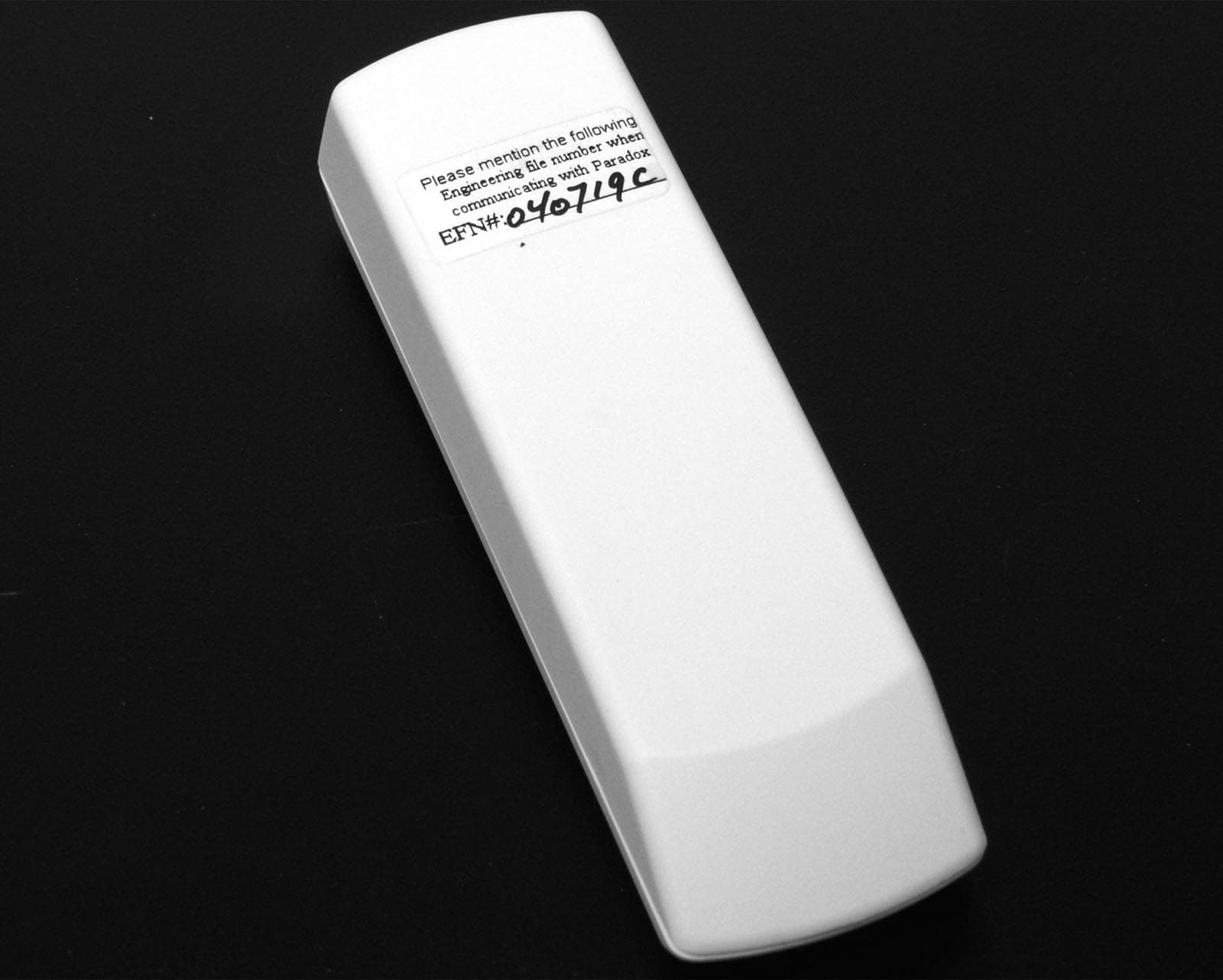
Click to zoom
Application Details
- Equipment Class
- DSC - Part 15 Security/Remote Control Transmitter
- Date of Grant
- Nov 02, 2004
- Application Purpose
- Original Equipment
- Date of Application
- Nov 02, 2004
- Equipment Note
- MG-DCTXP
- Frequency Range
- 433.92000000 - 433.92000000
- Company
- Paradox Security Systems
- Country
- Canada
Documents & Files
Document Text
Text extracted from the exhibit documents filed with the FCC. Open a document above to read the original.
Users Manual
MGDCTXP-TI00English Location & MountingWhen installing transmitters, please be sure there is at least 30cm (1ft) between each transmitter and 1.5m (5ft) between the transmitters and the receiver.The transmitter comes with one reed switch allowing you to place the transmitter horizontally (refer to Figure 1 on the reverse side of these instructions). Do not cut, bend or alter the antenna. Avoid mounting the door contact near or on metal as this may affect transmission. Universal Transmitter InputThe door contact can also be used as a universal transmitter. A switch or other security device can be connected to the universal transmitter input terminals in order to provide wireless transmission of the device's open/closed status to the receiver. If the reed switch is being used, the universal transmitter input will be disabled.Normally Open/Normally Closed (JP1)JP1 allows you to choose between a normally open and a normally closed circuit.When JP1 is ON, MG-DCTXP transmits a “zone open” message when the zone is open and transmits “zone closed” when the zone is closed.When JP1 is OFF, MG-DCTXP transmits a “zone open” message when the zone is closed and transmits “zone closed” when the zone is open.JP1 ON = Normally Open (default) JP1 OFF = Normally Closed JP2: Not Used JP3: Not Used After changing the jumper settings, press and release the anti-tamper switch in order to save the changes. Low Battery The door contact performs a battery test every 12 hours and if the battery voltage is below a certain level, the door contact sends a low battery signal to the receiver.Powering the UnitVerify proper polarity and insert two alkaline “AAA” batteries into the battery compartment. To replace the battery:1. Remove the old batteries.2. Press and release the anti-tamper switch several times. 3. Wait 60 seconds in order to reinitialize the unit. 4. Insert the new batteries while verifying proper polarity. After inserting the batteries, a power up sequence will begin (lasting 10-20 seconds) during which the door contact will not detect an open zone or tamper.Signal Strength TestIn order to verify the receiver’s reception of the MG-DCTXP’s signal, perform a signal strength test as described in the receiver’s Reference & Installation Manual before finalizing the installation of the MG-DCTXP. Prior to performing the test, verify that the batteries have been installed in order to power the door contact. Also, verify that the door contact has been assigned to a zone according to the instructions provided in the receiver’s Reference and Installation Manual . If the transmission is weak, relocating the transmitter by a few inches can greatly improve the reception.Testing the Unit1. Verify that the batteries are inserted properly. 2. Assign the door contact to a Magellan receiver. 3. Perform a signal strength test as detailed in the receiver’s manual. 4. Open and close the door or window to which the door contact is mounted and verify proper operation. Please note that the MG-DCTXP is compatible only with receivers that support Magellan. FrançaisEmplacement et montageLors de l’installation des émetteurs, s’assurer qu’il y ait un espace d’au moins 30 cm (1 pi) entre chaque émetteur et de 1,5 m (5 pi) entre les émetteurs et le récepteur.L’émetteur est muni d’un commutateur à lames permettant son installation en position horizontale (se référer à la Figure 1 au verso de ces instructions). Ne pas couper, courber ou altérer l’antenne. Éviter d’installer le contact de porte sur ou près d’une source métallique, car cela pourrait nuire à la transmission. Entrée d’émetteur universelLe contact de porte peut aussi être utilisé comme émetteur universel. Un interrupteur ou autre dispositif de sécurité peut être raccordé aux bornes d’entrée de l’émetteur universel afin d’offrir une transmission sans fil de l’état ouvert/fermé du dispositif au récepteur. Si le commutateur à lames est utilisé, l’entrée d’émetteur universel est désactivée.Circuit normalement ouvert / normalement fermé (JP1)Le cavalier 1 (JP1) permet le choix entre un circuit normalement ouvert et un circuit normalement fermé.Lorsque le cavalier 1 (JP1) est INSTALLÉ, le MG-DCTXP transmet le message « zone ouverte » quand la zone est ouverte et « zone fermée » quand la zone est fermée.Lorsque le cavalier 1 (JP1) est NON INSTALLÉ, le MG-DCTXP transmet le message « zone ouverte » quand la zone est fermée et « zone fermée » quand la zone est ouverte.JP1 INSTALLÉ (ON) = normalement ouvert (par défaut)JP1 NON INSTALLÉ (OFF) = normalement ferméJP2 : inutilisé JP3 : inutilisé Après avoir modifié les paramètres du cavalier, appuyer momentanément sur l’interrupteur de sécurité pour enregistrer les modifications. Pile faibleLe contact de porte fait un test de piles à toutes les 12 heures et, si la tension des piles est sous un certain niveau, le contact de porte envoie un signal de piles faibles au récepteur.Mise sous tension de l’unitéEn respectant la polarité, insérer deux piles alcalines AAA dans le compartiment à pile. Pour remplacer les piles : 1. Retirer les vieilles piles.2. Appuyer plusieurs fois sur l’interrupteur de sécurité. 3. Attendre 60 secondes afin que l’unité se réinitialise. 4. Insérer les nouvelles piles en respectant la polarité. Une fois les piles insérées, l’unité exécute une séquence de mise sous tension (d’une durée de 10 à 20 secondes) durant laquelle le contact de porte ne détecte ni ouverture de zone ni sabotage. Vérification de l’intensité du signalAfin de s’assurer que le récepteur reçoit bien le signal du MG-DCTXP, vérifier l’intensité du signal tel que décrit dans le Manuel d’installation et de référence du récepteur avant de finaliser l’installation du MG-DCTXP. Avant d’effectuer le test, s’assurer que les piles ont été installées pour alimenter le contact de porte. S’assurer aussi que le contact de porte ait été assigné à une zone selon les instructions fournies dans le Manuel d’installation et de référence du récepteur.Si la transmission est…
Text truncated - open the document above for the full version.
Attestation Statements
August 30th, 2004 Nemko Canada Inc 303 River Road Ottawa, Ontario, Canada K1V 1H2 Attn: Director of Certification Authority to Act as Agent On our behalf, I appoint Nemko Canada Inc. to act as our agent in the preparation of this application for equipment certification. I certify that submitted documents properly describe the device or system for which equipment certification is sought. I also certify that each unit manufactured, imported or marketed, as defined in the Federal Communications Commission’s regulations will have affixed to it a label identical to that submitted for approval with this application. For instances where our authorized agent signs the application for certification on our behalf, I acknowledge that all responsibility for complying with the terms and conditions for certification, as specified by Nemko Canada Inc, still resides with Paradox Security Systems, 780 Industrial Blvd, St-Eustache, Quebec, CANADA, J7R 5V3 Dated this 30th Day of August 2004 Agency agreement expiration date: April 30 th 2005 By: NABIL NAHOUL Signature Printed Title: Certification Manager On behalf of : Paradox Security Systems Telephone: (450) 491-7444 ext 209
Cover Letter(s)
August 30th, 2004 Equipment Authorization Division Federal Communications Commission 7435 Oakland Mills Road Columbia, MD 21046 FCC ID: KDYMGDCTXP Product Name: Magellan model MG-DCTXP Request for Confidentiality Pursuant to Sections 0.457 and 0.459 of the commissions rules, we hereby request that the following documents be held confidential: • Schematics • Block diagram These materials contain trade secrets and proprietary information and are not customarily released to the public. The public disclosure of this information might be harmful to the company and provide unjustified benefits to our competitors. Dated this 30th Day of August 2004 By: NABIL NAHOUL Signature Printed Title: Certification Manager On behalf of : Paradox Security Systems Telephone: (450) 491-7444 ext 209
Operational Description
MG-DCTXP Technical description: 4 main sections: 1- Battery 2- Trigger interfaces 3- Micro controller 4- RF transmitter circuit 1- Battery: To supply the current to the unit there is 2 “AA” type batteries. 2- 2 triggers are use to send an alarm: Magnetic reed switch and tamper switch 3- The micro controller is use to manage the whole unit. It monitors the battery voltage, manage the current consumption and format a message on event (door open, door close, low battery level, etc...) 4- The RF circuits RF2516 receives the formatted message from the micro controller and modulate it on a radio frequency carrier then transmit it. The type of modulation used is OOK (On and Off Keying). A helicoidally type antenna is use to convert the electric wave to electromagnetic wave.
Test Report
Master:PT15-Sub-C-15231 Date: November 12, 2001 Test Report: 4W26820.6 Applicant: PARADOX SECURITY SYSTEMS 780 INDUSTRIAL BLVD ST-EUSTACHE QUEBEC, CANADA, J7R 5V3 Equipment Under Test: MG-DCTXP (433MHz), Wireless Door Contact Sensor (EUT) FCC ID: KDYMGDCTXP In Accordance With: FCC Part 15, Subpart C, 15.231 Tested By: Nemko Canada Inc. 303 River Road, R.R. 5 Ottawa, Ontario K1V 1H2 Authorized By: Glen Westwell, Wireless Specialist Date: 13 October 2004 Total Number of Pages: 15 Nemko Canada Inc. FCC PART 15, SUBPART C, 15.231 PROJECT NO.: 4W26820.6 EQUIPMENT: MG-DCTXP (433MHz), Wireless Door Contact Sensor Page 2 of 15 Table of Contents Section 1. Summary of Test Results ...................................................................................3 Section 2. Equipment Under Test .......................................................................................5 Section 3. Transmission Requirements ..............................................................................6 Section 4. Radiated Emissions .............................................................................................8 Section 5. Occupied Bandwidth ........................................................................................12 Section 6. Block Diagrams .................................................................................................14 Section 7. Test Equipment List ..........................................................................................15 Nemko Canada Inc. FCC PART 15, SUBPART C, 15.231 PROJECT NO.: 4W26820.6 EQUIPMENT: MG-DCTXP (433MHz), Wireless Door Contact Sensor Page 3 of 15 Section 1. Summary of Test Results General All measurements are traceable to national standards. These tests were conducted on a sample of the equipment for the purpose of demonstrating compliance with Part 15, Subpart C. All tests were conducted using measurement procedure ANSI C63.4-1992. Radiated emissions are made on an open area test site. A description of the test facility is on file with the FCC. THIS TEST REPORT APPLIES ONLY TO THE ITEM(S) TESTED. THE FOLLOWING DEVIATIONS FROM, ADDITIONS TO, OR EXCLUSIONS FROM THE TEST SPECIFICATIONS HAVE BEEN MADE. NONE See “ Summary of Test Data”. TESTED BY: ______________________________ DATE: 7 October 2004 Chris Maidens, EMC Specialist Nemko Canada Inc. authorizes the above named company to reproduce this report provided it is reproduced in its entirety and for use by the company’s employees only. Any use which a third party makes of this report, or any reliance on or decisions to be made based on it, are the responsibility of such third parties. Nemko Canada Inc. accepts no responsibility for damages, if any, suffered by any third party as a result of decisions made or actions based on this report. This report applies only to the items tested. Nemko Canada Inc., a testing laboratory, is accredited by the Standards Council of Canada. The tests included in this report are within the scope of this accreditation. Nemko Canada Inc. FCC PART 15, SUBPART C, 15.231 PROJECT NO.: 4W26820.6 EQUIPMENT: MG-DCTXP (433MHz), Wireless Door Contact Sensor Page 4 of 15 Summary Of Test Data Name of Test Para. Number Results Transmission Requirements 15.231(a) Complied Radiated Emissions 15.231(b) Complied Occupied Bandwidth 15.231(c) Complied Frequency Tolerance 15.231(d) N/A(1) Periodic Alternate Field Strength Requirements 15.231(e) N/A(2) Powerline Conducted Emissions 15.207 N/A(3) Justification for N/A’s N/A(1) The EUT does not transmit in the band 40.66-40.070MHz N/A(2) The requirements of this section are not applicable to this EUT. N/A(3) The EUT is Battery Powered (2 “AAA” Batteries) Test Conditions: Indoor Temperature: 20°C Humidity: 49% Nemko Canada Inc. FCC PART 15, SUBPART C, 15.231 PROJECT NO.: 4W26820.6 EQUIPMENT: MG-DCTXP (433MHz), Wireless Door Contact Sensor Page 5 of 15 Section 2. Equipment Under Test General Equipment Information Manufacturer: Paradox Security Systems Company Number: 2438A Model No.: MG-DCTXP Serial No.: 006031 EUT Description: The EUT is a wireless door contact sensor for use with the Magellan alarm system. Date Received In Laboratory: September 14, 2004 Nemko Identification No.: 13 Frequency Range (or fixed frequency): Fixed, 433.92MHz Type of Modulation: ASK, 100% or OOK Emission Designator (TRC-43:) 64K3L1D Nemko Canada Inc. FCC PART 15, SUBPART C, 15.231 PROJECT NO.: 4W26820.6 EQUIPMENT: MG-DCTXP (433MHz), Wireless Door Contact Sensor Page 6 of 15 Section 3. Transmission Requirements Para. No.: 15.231(a) Test Performed By: Chris Maidens Date of Test: Sept. 27, 2004 Minimum Standard: 15.231(a) Continuous transmissions such as voice, video or data transmissions are not permitted. 15.231(a)(1) A manually operated transmitter shall employ a switch that will automatically deactivate the transmitter within not more than 5 seconds after being released. 15.231(a)(2) A transmitter activated automatically shall cease transmission within 5 seconds of activation. 15.231(a)(3) Periodic transmissions at regular pre-determined intervals are not permitted. However polling or supervisory transmissions to determine system integrity of transmitters used in security or safety applications are allowed if the periodic rate of transmission does not exceed one transmission of not more than one second duration per hour for each transmitter. 15.231(a)(4) Intentional radiators which are employed for radio control purposes during emergencies involving fire, security, and safety of life, when activated to signal an alarm, may operate during the pendency of the alarm. Test Results: Complies Test Data: Compliance was determined by verification of technical specifications and a functional test on the equipment. Nemko Canada Inc. FCC PART 15, SUBPART C, 15.231 PROJECT NO.: 4W26820.6 EQUIPMENT: MG-DCTXP (433MHz), Wireless Door Contact Sensor Page 7 of 15 Rationale for Compliance with Transmission Requirements 15.231(a)(1) : N/A- The EUT does …
Text truncated - open the document above for the full version.
Test Setup Photos
Nemko Canada Inc. FCC PART 15, SUBPART C, 15.231 PROJECT NO.: 4W26820.6 EQUIPMENT: MG-DCTXP (433MHz), Wireless Door Contact Sensor Page 11 of 15 OATS Set up Photo
Contact Information
Applicant
Alex Chaplik(Certification Manager)
Test Firm
Nemko Canada Inc. (Ottawa)Charles Neal
Technical Specifications
| # | Rule Parts | Frequency Range | Power Output |
|---|---|---|---|
| 1 | 15.231 | 433.92 MHz - 433.92 MHz | - |
Other Applications from Paradox Security Systems
KDYX45
May 07, 2026Hybrid Head Unit/Console
Equipment Class
DSS - Part 15 Spread Spectrum TransmitterKDYZP2M
Dec 23, 2025Dual Input /Output Wireless Bus Expander Two Garage Door
Equipment Class
DSS - Part 15 Spread Spectrum TransmitterKDYK70M
Dec 12, 20257 inch Touchscreen Keypad
Equipment Class
DTS - Digital Transmission SystemKDYDCT12M
Nov 25, 2025Door /Window Magnetic Contact + Zone
Equipment Class
DSS - Part 15 Spread Spectrum Transmitter
KDYPGM8M
Nov 25, 2025PGM Expander
Equipment Class
DSS - Part 15 Spread Spectrum Transmitter