KDYMGDCTXP2Door Contact Transmitter
Paradox Security Systems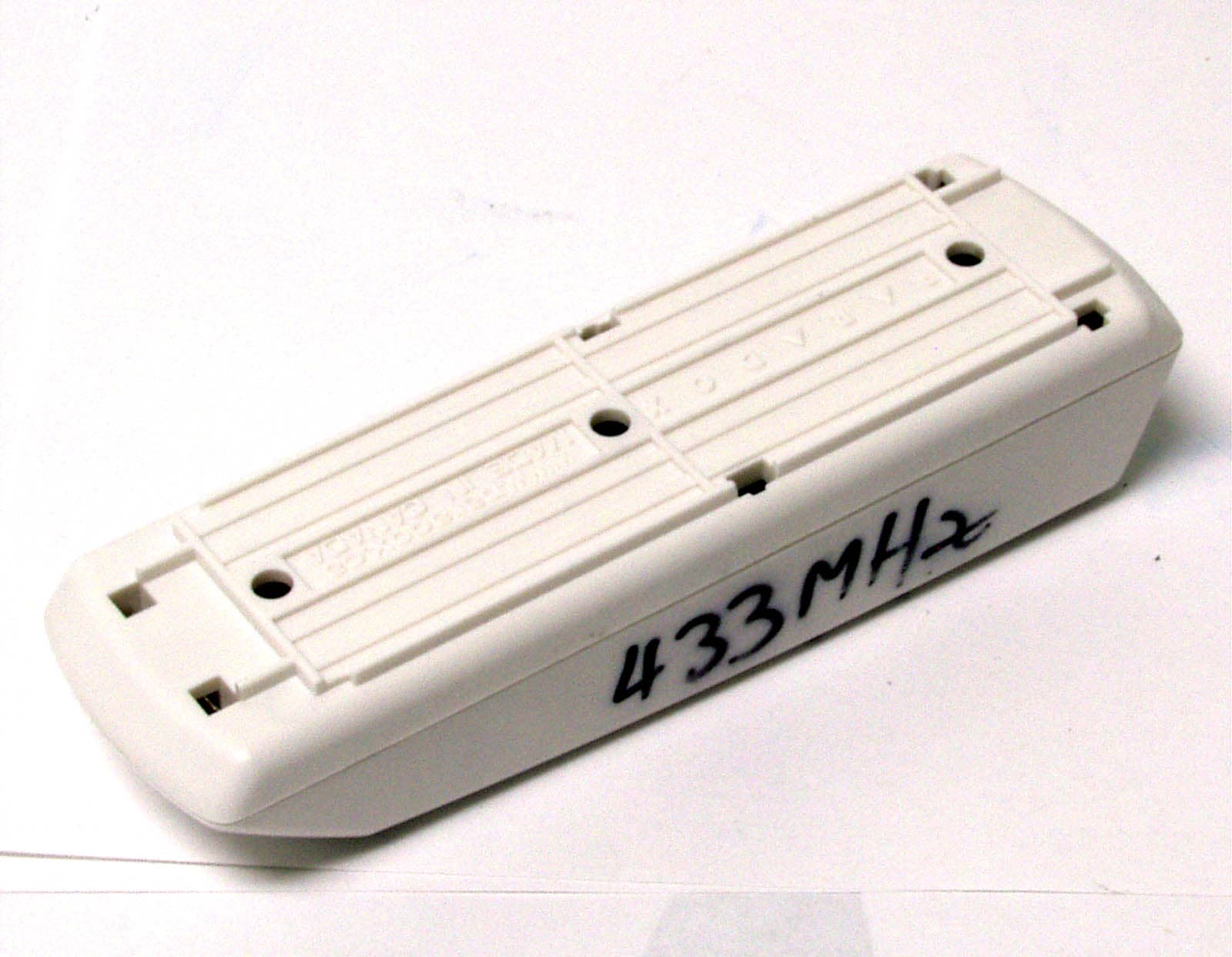
Click to zoom
Application Details
- Equipment Class
- DSC - Part 15 Security/Remote Control Transmitter
- Date of Grant
- Oct 29, 2006
- Application Purpose
- Original Equipment
- Date of Application
- Oct 29, 2006
- Equipment Note
- Door Contact Transmitter
- Frequency Range
- 433.92000000 - 433.92000000
- Company
- Paradox Security Systems
- Country
- Canada
Documents & Files
Document Text
Text extracted from the exhibit documents filed with the FCC. Open a document above to read the original.
Users Manual
MGDCTXP2-TI03 780 Industriel Blvd., Saint-Eustache (Quebec) J7R 5V3 CANADA Tel.: (450) 491-7444 Fax: (450) 491-2313 www.paradox.ca Printed in Canada - 01/2006 Instructions Instrucciones Wireless 2-Zone Door Contact (Universal Transmitter) MG-DCTXP2 V3.0 No se debe cortar, doblar o alterar la antena. Evitar ubicar el contacto de puerta cerca de o sobre metal pues esto podría afectar la transmisión AAA AAA JP2 JP1 Ubicación y MontajeDebe haber una distancia de por lo menos 30cm (1ft) entre cada transmisor y 1.5m (5ft) entre los transmisores y el receptor. PuentesJP1 ON Normalmente Abierto Entrada Universal / de Interruptor de Láminaabierto = señal de “zona abierta”cerrado = señal de “zona cerrada” JP1 OFF Normalmente Cerrado Entrada Universal / de Interruptor de Láminaabierto = señal de “zona cerrada”cerrado = señal de “zona abierta” JP2 SIN USAR Modo de AprendizajeEl Modo de Aprendizaje permite transmitir el número de serie de cada entrada. Para acceder al Modo de Aprendizaje, abrir la cubierta del contacto y esperar que las luces LED dejen de parpadear. Entrada Número de Serie Confirmación Visual Entrada 1 (interruptor de lámina): Pulsar y soltar una vez el interruptor antisabotaje. SN (e.g. 240 000) La luz LED parpadea cuatro veces. Entrada 2 (transmisor universal): Pulsar y soltar dos veces el interruptor antisabotaje al interior de un segundo. SN+1 (e.g. 240 001) La luz LED parpadea rápidamente dos veces en cuatro ocasiones. Español El MG-DCTXP2 puede aceptar dos entradas simultáneamente (entrada de interruptor de lámina y universal). Transmite dos números de serie diferentes (NS), uno por cada entrada, los que son siempre NS y NS+1(e.g. 240 000 & 240 001). Un interruptor u otro dispositivo de seguridad puede ser conectado a los terminales de entrada de transmisor universal para obtener transmisión inalámbrica del estado de abierto/cerrado del dispositivo. Prueba de la Unidad1. Efectuar una prueba de fuerza de la señal antes de terminar la instalación. Si la transmisión es débil, mover el transmisor tan sólo unos pocos centímetros para mejorar la recepción. 2. Verificar si la batería ha sido insertada correctamente. 3. Asignar el contacto de puerta a un receptor Magellan. 4. Abrir y cerrar la puerta o ventana asignada para comprobar el buen funcionamiento. Anti- sabotaje Encendido de la UnidadInsertar dos baterías alcalinas “AAA”, veri ficando la correcta polaridad. Luego de haber insertado las baterías, se inicia una secuencia de encendido (10 y 20 seg.) durante la cual el contacto de puerta no detectará una zona abierta o un sabotaje. Cambio de BateríasPara cambiar las baterías:1. Sacar las baterías usadas.2. Pulsar y soltar varias vece s el interruptor anti-sabotaje. 3. Esperar 60 segundos para reinicializar la unidad.. Batería BajaEl contacto de puerta efectúa una prueba de bater ía cada 12 horas. Si el voltaje es menor que 2.3V por cuatro pruebas de baterías consec utivas (48 horas), la luz LED roja parpadea a intervalos de 5 segundos y el MG-DCT XP2 transmite una señal de batería baja. Do not cut, bend or alter the antenna. Avoid mounting the door contact near or on metal as this may affect transmission. AAA AAA JP2 JP1 Location & MountingThere should be at least 30cm (1ft) between each transmitter and 1.5m (5ft) between the transmitters and the receiver. JumpersJP1 ON Normally Open Reed Switch/Universal Input:open = “zone open” signalclosed = “zone closed” signal JP1 OFF Normally Closed Reed Switch/Universal Input:open = “zone closed” signalclosed = “zone open” signal JP2 NOT USED Learn ModeLearn Mode allows you to transmit the serial numbers of each input. To enter Learn Mode, open the cover and wait until the LED stops flashing. Input Serial Number Visual Confirmation Input 1 (reed switch): Press and release the anti-tamper switch once. SN (e.g. 240 000) The LED will flash once four times. Input 2 (universal transmitter): Press and release the anti-tamper switch twice within one second. SN+1 (e.g. 240 001) The LED will flash twice rapidly four times. English The MG-DCTXP2 can support two inputs simultaneously (reed switch & universal input). It transmits two different serial numbers (SN), one for each input, which are always SN and SN+1(e.g. 240 000 & 240 001). A switch or other security device can be connected to the universal transmitter input terminals to provide wireless transmission of the device's open/closed status. Testing the Unit1. Perform a signal strength test before finalizing installation. If the transmission is weak, relocate the transmitter by a few inches to improve reception. 2. Verify that the batteries are inserted properly. 3. Assign the door contact to a Magellan receiver. 4. Open and close the assigned door/ window to verify proper operation. Anti- Tamper Powering the UnitVerify proper polarity and insert two alkaline “AAA” batteries. After inserting batteries, a power up sequence will begin (10-20 seconds ) during which the door contact will not detect an open zone or tamper. Replacing the BatteriesTo replace batteries:1. Remove the old batteries.2. Press and release the anti-tamper switch several times.3. Wait 60 seconds to reinitialize the unit. Low Battery The door contact performs a battery test every 12 hours. If the voltage is below 2.3V after four consecutive battery tests (48 hrs.), the red LED will flash at 5 second intervals and the MG-DCTXP2 will transmit a low battery signal. Technical SpecificationsReed switch w/magnet One (high sensitivity) with a standard gap of 1cm (0.4”) from magnet Input Response Time 45 ms RF frequency 433MHz or 868MHz Power 3.0Vdc (Two “AAA” Alkaline batteries)* Battery life Up to three years** Range (typical in a residential environment) Spectra 1759MG: 45m (150ft)MG-6060/MG-6030: 30m (100ft)MG-RCV3: 60m (200ft) Anti-tamper switch Yes Compatibility Spectra 1759MG, Magellan console (MG-6060/MG-6030), and MG- RCV3 Dimensions 11cm X 3.2cm X 2.5cm (4.4in X 1.3in X 1.0in) Operating temperature 0°C to 49°C (32°F to 120°F…
Text truncated - open the document above for the full version.
Cover Letter(s)
July 11th, 2006 Nemko Canada Inc 303 River Road Ottawa, Ontario, Canada K1V 1H2 Attn: Director of Certification Authority to Act as Agent On our behalf, I appoint Nemko Canada Inc. to act as our agent in the preparation of this application for equipment certification. I certify that submitted documents properly describe the device or system for which equipment certification is sought. I also certify that each unit manufactured, imported or marketed, as defined in the Federal Communications Commission’s regulations will have affixed to it a label identical to that submitted for approval with this application. For instances where our authorized agent signs the application for certification on our behalf, I acknowledge that all responsibility for complying with the terms and conditions for certification, as specified by Nemko Canada Inc, still resides with Paradox Security Systems, 780 Industrial Blvd, St-Eustache, Quebec, CANADA, J7R 5V3 Dated this 11th Day of July 2006 Agency agreement expiration date: January 11 th 2006 By: NABIL NAHOUL Signature Printed Title: Certification Manager On behalf of : Paradox Security Systems Telephone: (450) 491-7444 ext 209
Cover Letter(s)
July 11th, 2006 Equipment Autorisation Division Federal Communications Commission 7435 Oakland Mills Road Columbia, MD 21046 FCC ID: KDYMGDCTXP2 Product Name: Magelan model MGDCTXP2 Request for Confidentiality Pursuant to Sections 0.457 and 0.459 of the commissions rules, we hereby request that the following documents be held confidential: • Schematics • Block diagram These materials contain trade secrets and proprietary information and are not customarily released to the public. The public disclosure of this information might be harmful to the company and provide unjustified benefits to our competitors. Dated this 11th Day of July 2006 By: NABIL NAHOUL Signature Printed Title: Certification Manager On behalf of : Paradox Security Systems Telephone: (450) 491-7444 ext 209
ID Label/Location Info
LABEL REQUIREMENTS RF IC & FCC Paeadox Security Systems Model No.: MG-DCTXP2 IC: 2438A-MGDCTXP2 FCC ID: KDYMGDCTXP2 * This device complies with Part 15 of the FCC Rules. Operation is subject to the following two conditions: (1) This device may not cause harmful interference, and (2) This device must accept any interference received, including interference that may cause undesired operation. Made in CANADA THE ABOVE INFORMATION APPEARS ON THE OUTSIDE OF THE CERTIFIED UNIT. See label location exhibit to show location of the specified information.
Operational Description
Description of the Blocks 1. The unit is powered with two “AAA” common alkaline battery type. 2. The microcontroller is the heart of the unit and controls the behavior of all functionalities as well as reports any changes in the state of the unit i.e.: Low battery, detection of intrusion, etc. Its internal clock frequency is 4MHz 3. The reed switch, external switch connector and tamper switch are the security features of the units: there is one reed switch, one connection for an external reed switch or any other dry contact (one independent serial number is assigned to each of them) and there is a tamper switch that sends an alarm in case of an attempt to open the casing of the unit. 4. The transmitter is a RF modulator that is modulating its amplitude by succeeding on and off state of its RF energy (OOK, On and Off keying), the baud rate is about 2.5kbaud/s 5. The transmitter uses a PLL (phase locked loop) which use a divider by 32 for the sampling of its main frequency VCO (voltage controlled oscillator) and is compared against a crystal of the same divided frequency. So the output of the transmitter is 32 times the frequency of the crystal it uses. We have two model of transmitter for this unit, one for the output frequency of 433.92MHz and one for 868.35 MHz which lead to a crystal frequency of 13.56MHz for the 433.92MHz IC and 27.13594MHz for the 868.35MHz transmitter. 6. There is a filtering and matching circuit for the maximum transfer of energy to the antenna which consists of capacitors and inductors. 7. The output is hooked to helicoids antennas with an appropriate length according to the frequency it have to transmit.
Test Report
FCC Part 15 Subpart C, 15.231 : June 2006 Test Report: 6W69730.6 Applicant: Paradox Security Systems 780 Industrial Blvd Ste-Eustache, Quebec J7R 5V3 Apparatus: MG-DCTXP2 FCC ID: KDYMGDCTXP2 In Accordance With: FCC Part 15 Subpart C, 15.231 Periodic operation in the band 40.66-40.70MHz and above 70 MHz. Tested By: Nemko Canada Inc. 303 River Road Ottawa, Ontario K1V 1H2 Authorized By: Jin Xu, Wireless Specialist Date: September 28, 2006 Total Number of Pages: 19 Nemko Canada Inc. REPORT SUMMARY Report Number: 6W69730.6 FCC ID: KDYMGDCTXP2 Specification: FCC Part 15 Subpart C, 15.231 Page 2 of 19 Report Summary These tests were conducted on a sample of the equipment for the purpose of demonstrating compliance with Part 15, Subpart C. Radiated tests were conducted in accordance with ANSI C63.4-2003. Radiated emissions are made on an open area test site. A description of the test facility is on file with the FCC. The assessment summary is as follows: Apparatus Assessed: MG-DCTXP2 Specification: FCC Part 15 Subpart C, 15.231 Compliance Status: Complies Exclusions: None Non-compliances: None Report Release History: Original Release Author: Jason Nixon, Telecom Specialist Note that the results contained in this report relate only to the items tested and were obtained in the period between the date of initial receipt of samples and the date of issue of the report. This test report has been completed in accordance with the requirements of ISO/IEC 17025. Nemko Canada Inc. authorizes the applicant to reproduce this report provided it is reproduced in its entirety and for use by the company’s employees only. Any use which a third party makes of this report, or any reliance on or decisions to be made based on it, are the responsibility of such third parties. Nemko Canada Inc. accepts no responsibility for damages, if any, suffered by any third party as a result of decisions made or actions based on this report. Nemko Canada Inc. REPORT SUMMARY Report Number: 6W69730.6 FCC ID: KDYMGDCTXP2 Specification: FCC Part 15 Subpart C, 15.231 Page 3 of 19 TABLE OF CONTENTS Report Summary......................................................................................................................................... 2 Section 1 : Equipment Under Test............................................................................................................. 4 1.1 Product Identification .................................................................................................................................4 1.2 Samples Submitted for Assessment............................................................................................................4 1.3 Theory of Operation ...................................................................................................................................4 1.4 Technical Specifications of the EUT ..........................................................................................................5 1.5 Block Diagram of the EUT.........................................................................................................................5 Section 2 : Test Conditions......................................................................................................................... 6 2.1 Specifications .............................................................................................................................................6 2.2 Deviations From Laboratory Test Procedures ............................................................................................6 2.3 Test Environment .......................................................................................................................................6 2.4 Test Equipment...........................................................................................................................................6 Section 3 : Observations ............................................................................................................................. 7 3.1 Modifications Performed During Assessment ............................................................................................7 3.2 Record Of Technical Judgements ...............................................................................................................7 3.3 EUT Parameters Affecting Compliance .....................................................................................................7 3.4 Test Deleted................................................................................................................................................7 3.5 Additional Observations .............................................................................................................................7 Section 4 : Results Summary ..................................................................................................................... 8 4.1 FCC Part 15 Subpart C : Test Results ........................................................................................................9 Appendix A : Test Results ........................................................................................................................ 10 Clause 15.209(a) Radiated Emissions within Restricted Bands ..........................................................................10 Clause 15.231(a) Conditions for intentional radiators to comply with periodic operation ..................................11 Clause 15.231(b) Radiated Emissions .................................................................................................................13 Clause 15.231(c) 20dB Bandwidth ......................................................................................................................16 Appendix B : Setup Photographs ............................................................................................................ 17 Appendix C : Block Diagram o…
Text truncated - open the document above for the full version.
Test Setup Photos
Spurious Emissions Setup:
Contact Information
Applicant
Alex Chaplik(Certification Manager)
Technical Contact
Non-Technical Contact
Nemko Canada Inc.Joanna Olszanowska
[email protected]613-737-9680
Test Firm
Nemko Canada Inc. (Ottawa)Charles Neal
Technical Specifications
| # | Rule Parts | Frequency Range | Power Output |
|---|---|---|---|
| 1 | 15.231 | 433.92 MHz - 433.92 MHz | - |
Other Applications from Paradox Security Systems
KDYX45
May 07, 2026Hybrid Head Unit/Console
Equipment Class
DSS - Part 15 Spread Spectrum TransmitterKDYZP2M
Dec 23, 2025Dual Input /Output Wireless Bus Expander Two Garage Door
Equipment Class
DSS - Part 15 Spread Spectrum TransmitterKDYK70M
Dec 12, 20257 inch Touchscreen Keypad
Equipment Class
DTS - Digital Transmission SystemKDYDCT12M
Nov 25, 2025Door /Window Magnetic Contact + Zone
Equipment Class
DSS - Part 15 Spread Spectrum Transmitter
KDYPGM8M
Nov 25, 2025PGM Expander
Equipment Class
DSS - Part 15 Spread Spectrum Transmitter