KDYOMNDCT2Wireless Door Contact
Paradox Security Systems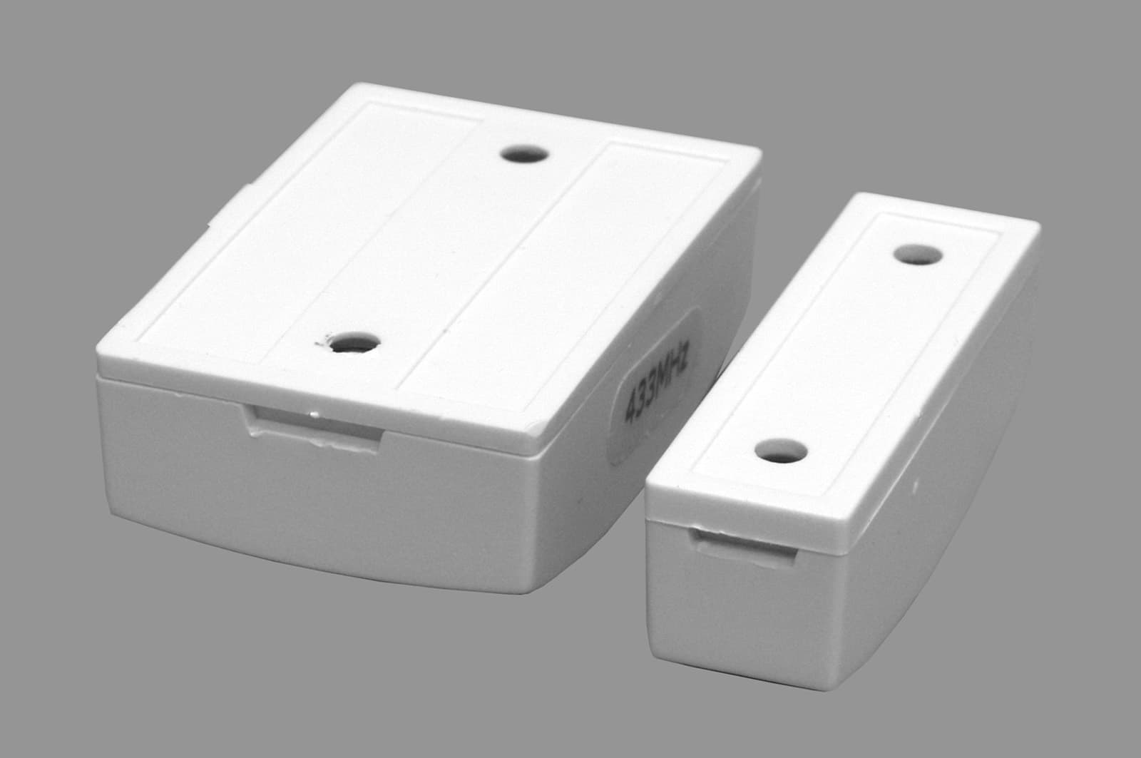
Click to zoom
Application Details
- Equipment Class
- DSC - Part 15 Security/Remote Control Transmitter
- Date of Grant
- Feb 03, 2003
- Application Purpose
- Original Equipment
- Date of Application
- Feb 03, 2003
- Equipment Note
- Wireless Door Contact
- Frequency Range
- 433.00000000 - 433.00000000
- Company
- Paradox Security Systems
- Country
- Canada
Documents & Files
Document Text
Text extracted from the exhibit documents filed with the FCC. Open a document above to read the original.
Users Manual
OMNDCT2-TI01English Location & MountingWhen installing transmitters, be sure there is at least 30cm (1ft) between each Omnia wireless transmitter. In addition, ensure a distance of 1.5m (5ft) between transmitters and the receiver. Install the transmitter either vertically or horizontally, by placing the magnet in line with the reed switch. The reed switch is located under the PCB and is aligned with the arrow on the cover (see figure 2 on reverse side). When closing the cover and back plate, ensure that the arrows match otherwise the unit will not snap together (see figure 2 on reverse side). Check-in Supervision TimerThe two jumpers set the time interval in which the door contact communicates a chec k-in signal. Set the jumpers as outlined in table 1 on the reverse side. After changing the jumper settings press and release the anti-tamper switch, in order to save the changes. Low Battery If the battery voltage drops below a certain level, the door contact sends a signal to the receiver.Powering the UnitVerify proper polarity and insert the 3V lithium battery (CR2450) into the battery compartment. To replace the battery: 1. Remove the old battery.2. Press and release the anti-tamper switch several times. 3. Wait 60 seconds in order to reinitialize the unit. 4. Insert the new battery while verifying proper polarity. Danger of explosion exists if the lithium battery is incorrectly replaced. Replace only with the same or equivalent type recommended by the manufacturer. Dispose of used batteries according to the manufacturer’s instructions. After inserting the battery, a power up sequence will begin (lasting 10-20 seconds) during which the door contact will not detect an open zone or tamper. Testing the Unit1. Verify that the battery is inserted properly. 2. Assign the door contact to a compatible receiver. 3. Perform a signal strength test as detailed in the appropriate receiver’s manual. 4. Open and close the door or window to which the door contact is mounted and verify proper operation. FrançaisEmplacement et MontageAu moment d’installer les transmetteurs, s’assurer qu’il y ait au moins un espace de 30 cm (1 pi) entre chaque transmetteur sans fil Omnia. S’assurer également que la distance minimale entre les transmetteurs et le récepteur soit de 1,5 m (5 pi). Installer le transmetteur en position verticale ou horizontale en alignant l’aimant avec le contact magnétique; ce dernier est situé sous le circuit imprimé et est aligné avec la flèche sur le couvercle (voir figure 2 au verso). Au moment d’assembler le couvercle et la plaque arrière, s’assurer que les flèches soient alignées, sans quoi les deux parties de l’unité ne pourront pas s’accrocher l’une à l’autre (voir figure 2 au verso). Minuterie de Supervision de PrésenceLes deux cavaliers servent à régler la fréquence à laquelle le contact de porte transmet un signal de présence au récepteur. Régler les cavaliers comme illustré à la table 1, au verso. Après avoir modifié la configuration des cavaliers, appuyer momentanément sur l’interrupteur antisabotage afin que les modifications soient enregistrées. Pile FaibleSi la tension de la pile chute en deça d’une certaine tension, le contact de porte transmet un signal au récepteur. Mise sous tension de l’UnitéEn respectant la polarité, insérer la pile au lithium de 3V (CR2450) dans le compartiment à pile. Pour remplacer la pile : 1. Retirer la vieille pile.2. Appuyer plusieurs fois sur l’interrupteur antisabotage. 3. Attendre 60 secondes afin que l’unité se réinitialise. 4. Insérer la nouvelle pile en respectant la polarité. Si la batterie au lithium n’est pas remplacée correctement, il y a danger d’explosion. Remplacer seulement avec le même type de batterie ou avec un équivalent recommandé par le fabricant. Selon les directives du fabricant, se départir des batteries qui ont déjà servi. Une fois la pile insérée dans le contact de porte, l’unité exécutera une séquence de mise sous tension (d’une durée de 10 à 20 secondes) durant laquelle le contact de porte ne détectera pas une ouverture ou un sabotage de la zone . Mise à l’essai de l’Unité1. S’assurer que la pile soit insérée correctement. 2. Assigner le contact de porte à un récepteur compatible. 3. Vérifier la force du signal en se référant à la procédure décrite dans le manuel du récepteur approprié. 4. Ouvrir et fermer la porte/fenêtre sur laquelle le contact est installé et s’assurer que le contact fonctionne correctement. EspañolUbicación y MontajeCuando instale los transmisores, asegure una distancia de por lo menos 30cms (1pie) entre cada transmisor inalámbrico Omnia. Además, guarde una distancia de 1.5m (5pies) entre los transmisores y el receptor. Instale el transmisor ya sea vertical u horizontalmente, alineando el imán con el interruptor de láminas. El interruptor de lámina se encuentra debajo de la placa de circuito impreso y se alinea con la flecha de la cubierta (Ver figura 2). Al cerrar la cubierta y la placa posterior, asegúrese que las flechas están alineadas pues de lo contrario la unidad no podrá ser acoplada (ver figura 2). Tiempo de SupervisiónLos dos puentes determinan el intervalo de tiempo en el cual el contacto de puerta envía una señal de verificación. Configure los puentes como se señala en la tabla 1 al verso. Después de cambiar la configuración del puente pulse y suelte el interruptor antisabotaje, para guardar los cambios. Alimentación de la UnidadVerifica la polaridad e inserte la batería de litio de 3V (CR2450) en el compartimiento de la batería. Para cambiar la batería:1. Quite la batería vieja.2. Pulse y suelte el interruptor antisabotaje varias veces. 3. Espere 60 segundos mientras se reinicializa la unidad. 4. Inserte la nueva batería verificando la polaridad. Peligro de explosión si se cambia la batería de litio incorrectamente. Cámbiar sólo por una batería similar o equivalente sugerida por el fabricante. Disponga de las baterías usadas según las instrucciones del fabricante. Luego de haber puesto la…
Text truncated - open the document above for the full version.
Cover Letter(s)
Wednesday, January 22, 2003 Office of Engineering & Technology Federal Communications Commission Washington, D.C. 20554 Subject: Request for continuous confidentiality of technical information per Sections 0.459 and 0.457 (d) (2) (I) of CFR 47. FCC ID: KDYOMNDCT2 To Whom It May Concern: Paradox Security Systems is hereby filing this request for continuous confidentiality of the specified items submitted with the application for certification (Form 731) with proposed identifier KDYOMNDCT2 The technical documentation for which continuous confidentiality is sought is: • Schematic diagrams, PCB Layers • Components List (BOM) • Bloc Diagram • Technical Description This technical documentation is a part of the material supporting the Form 731 application for certification, which this request for confidentiality accompanies. The schematic diagrams disclose proprietary information and technical data that Paradox Security Systems would guard from its competitors and would not make available to the public. This proprietary information constitutes a trade secret and is not a part of the product documentation that would be made available to the customers of Paradox Security Systems. It would be potentially injurious to Paradox Security Systems in the development of this innovative proprietary product to make available for public disclosure the trade secret technical information specified in this request. If you have any questions or comments, please do not hesitate to contact me, Marc Bertrand Certification Manager Paradox Security Systems e-mail: [email protected]
ID Label/Location Info
Monday, February 03, 2003 Office of Engineering & Technology Federal Communications Commission Washington, D.C. 20554 FCC LABEL: Adhesive label AVERY# 05420 (0.125” x 1”) laser printed, applied on the back of the module. 433 MHz FCC ID: KDYOMNDCT2 Marc Bertrand Certification Manager Paradox Security Systems e-mail: [email protected]
Test Report
Master:PT15-Sub-C-15231 Date: November 12, 2001 Test Report:2W06711.2 Applicant:Paradox Security Systems 780 Industrial Blvd. Ste-Eustache, Quebec J7R 5V3 Equipment Under Test:OMN DCT2 433 MHz (EUT)Wireless Door Contact In Accordance With:FCC Part 15, Subpart C, 15.231 Tested By:Nemko Canada Inc. 303 River Road, R.R. 5 Ottawa, Ontario K1V 1H2 Authorized By:Glen Westwell, Wireless Technologist Date:22 January 2003 Total Number of Pages:17 Nemko Canada Inc.FCC PART 15, SUBPART C, 15.231 PROJECT NO.: 2W06711.2 EQUIPMENT: OMN DCT2 433MHz Wireless Door Contact Page 2 of 17 Table of Contents Section 1. Summary of Test Results......................................................................................3 Section 2. Equipment Under Test.........................................................................................5 Section 3. Transmission Requirements.................................................................................8 Section 4. Radiated Emissions.............................................................................................11 Section 5. Occupied Bandwidth..........................................................................................14 Section 6. Block Diagrams...................................................................................................16 Section 7.Test Equipment List............................................................................................17 Nemko Canada Inc.FCC PART 15, SUBPART C, 15.231 PROJECT NO.: 2W06711.2 EQUIPMENT: OMN DCT2 433MHz Wireless Door Contact Page 3 of 17 Section 1.Summary of Test Results General All measurements are traceable to national standards. These tests were conducted on a sample of the equipment for the purpose of demonstrating compliance with Part 15, Subpart C. All tests were conducted using measurement procedure ANSI C63.4-1992. Radiated emissions are made on an open area test site. A description of the test facility is on file with the FCC. THIS TEST REPORT RELATES ONLY TO THE ITEM(S) TESTED. THE FOLLOWING DEVIATIONS FROM, ADDITIONS TO, OR EXCLUSIONS FROM THE TEST SPECIFICATIONS HAVE BEEN MADE. See “ Summary of Test Data”. Test Performed By: ______________________Date: 20 January 2003 Russell Grant Nemko Canada Inc. authorizes the above named company to reproduce this report provided it is reproduced in its entirety and for use by the company’s employees only. Any use which a third party makes of this report, or any reliance on or decisions to be made based on it, are the responsibility of such third parties. Nemko Canada Inc. accepts no responsibility for damages, if any, suffered by any third party as a result of decisions made or actions based on this report. This report applies only to the items tested. Nemko Canada Inc.FCC PART 15, SUBPART C, 15.231 PROJECT NO.: 2W06711.2 EQUIPMENT: OMN DCT2 433MHz Wireless Door Contact Page 4 of 17 Summary Of Test Data Name of TestPara. NumberResults Transmission Requirements15.231(a)Complies Radiated Emissions15.231(b)Complies Occupied Bandwidth15.231(c)Complies Frequency Tolerance15.231(d)NA Periodic Alternate Field Strength Requirements15.231(e)NA Powerline Conducted Emissions15.207NA Test Conditions: IndoorTemperature:20°C Humidity:10% OutdoorTemperature:15°C Humidity:5% Nemko Canada Inc.FCC PART 15, SUBPART C, 15.231 PROJECT NO.: 2W06711.2 EQUIPMENT: OMN DCT2 433MHz Wireless Door Contact Page 5 of 17 Section 2.Equipment Under Test General Equipment Information Manufacturer: Paradox Security Systems Model No.: OMN DCT2 Serial No.: None Date Received In Laboratory: Dec 4, 2002 Nemko Identification No.: 1 Wireless Door Contact Transmit Frequency: 433 MHz Fixed Emission Designator: 124KL1D Modulation:Pulse Modulated Carrier On/Off Modulation Correction Factor:Duty Cycle 20Log(75/100)=-2.5dB Power:3V Lithium Battery Nemko Canada Inc.FCC PART 15, SUBPART C, 15.231 PROJECT NO.: 2W06711.2 EQUIPMENT: OMN DCT2 433MHz Wireless Door Contact Page 6 of 17 Nemko Canada Inc.FCC PART 15, SUBPART C, 15.231 PROJECT NO.: 2W06711.2 EQUIPMENT: OMN DCT2 433MHz Wireless Door Contact Page 7 of 17 Nemko Canada Inc.FCC PART 15, SUBPART C, 15.231 PROJECT NO.: 2W06711.2 EQUIPMENT: OMN DCT2 433MHz Wireless Door Contact Page 8 of 17 Section 3.Transmission Requirements Para. No.: 15.231(a) Test Performed By: Russell GrantDate of Test: Jan 20, 2003 Minimum Standard:15.231(a) Continuous transmissions such as voice, video or data transmissions are not permitted. 15.231(a)(1) A manually operated transmitter shall employ a switch that will automatically deactivate the transmitter within not more than 5 seconds after being released. 15.231(a)(2) A transmitter activated automatically shall cease transmission within 5 seconds of activation. 15.231(a)(3) Periodic transmissions at regular pre-determined intervals are not permitted. However polling or supervisory transmissions to determine system integrity of transmitters used in security or safety applications are allowed if the periodic rate of transmission does not exceed one transmission of not more than one second duration per hour for each transmitter. 15.231(a)(4) Intentional radiators which are employed for radio control purposes during emergencies involving fire, security, and safety of life, when activated to signal an alarm, may operate during the pendency of the alarm. Test Results:Complies Test Data:Compliance was determined by verification of technical specifications and a functional test on the equipment. Nemko Canada Inc.FCC PART 15, SUBPART C, 15.231 PROJECT NO.: 2W06711.2 EQUIPMENT: OMN DCT2 433MHz Wireless Door Contact Page 9 of 17 Rationale for Compliance with Transmission Requirements 15.231(a)(1) : The transmitter is deactivated within 2.3 seconds. 15.231(a)(2) : No automatic activation. 15.231(a)(3) : No periodic transmissions. 15.231(a)(4) : 2.3 seconds activation. Nemko Canada Inc.FCC PART 15, SUBPART C, 15.231 PROJECT NO.: 2W06711.2 EQUIPMENT: OMN DCT2 433MHz Wireless Door Contact Page 10 of …
Text truncated - open the document above for the full version.
Test Setup Photos
Nemko Canada Inc.FCC PART 15, SUBPART C, 15.231 PROJECT NO.: 2W06711.2 EQUIPMENT: OMN DCT2 433MHz Wireless Door Contact Page 12 of 17 Radiated Emissions Set Up
Contact Information
Applicant
Alex Chaplik(Certification Manager)
Test Firm
Nemko Canada Inc.Stuart Beck
Technical Specifications
| # | Rule Parts | Frequency Range | Power Output |
|---|---|---|---|
| 1 | 15.231 | 433 MHz - 433 MHz | - |
Other Applications from Paradox Security Systems
KDYX45
May 07, 2026Hybrid Head Unit/Console
Equipment Class
DSS - Part 15 Spread Spectrum TransmitterKDYZP2M
Dec 23, 2025Dual Input /Output Wireless Bus Expander Two Garage Door
Equipment Class
DSS - Part 15 Spread Spectrum TransmitterKDYK70M
Dec 12, 20257 inch Touchscreen Keypad
Equipment Class
DTS - Digital Transmission SystemKDYDCT12M
Nov 25, 2025Door /Window Magnetic Contact + Zone
Equipment Class
DSS - Part 15 Spread Spectrum Transmitter
KDYPGM8M
Nov 25, 2025PGM Expander
Equipment Class
DSS - Part 15 Spread Spectrum Transmitter