KDYOMNPMD75Motion Detector
Paradox Security Systems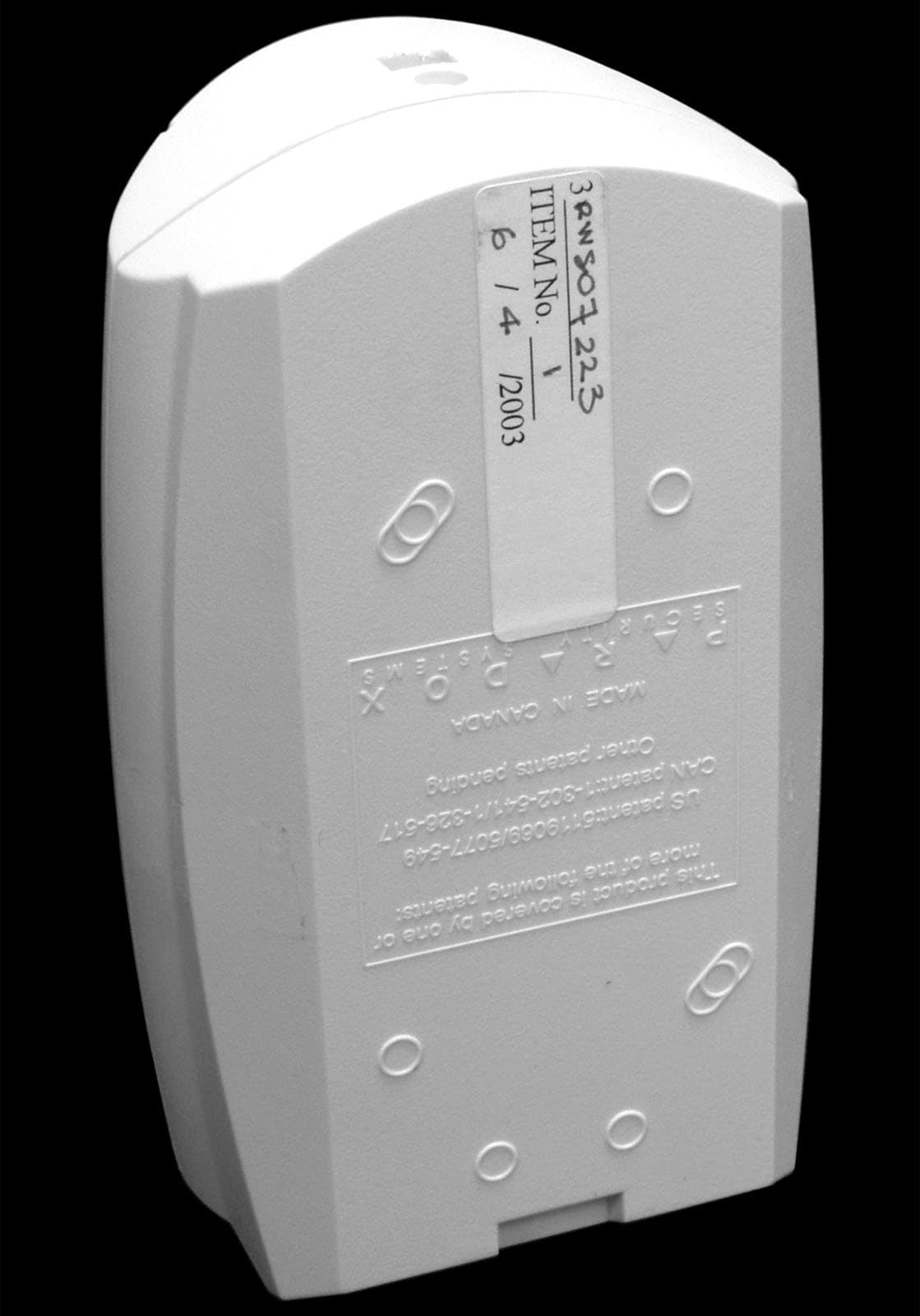
Click to zoom
Application Details
- Equipment Class
- DSC - Part 15 Security/Remote Control Transmitter
- Date of Grant
- Jul 22, 2003
- Application Purpose
- Original Equipment
- Date of Application
- Jul 21, 2003
- Equipment Note
- Motion Detector
- Frequency Range
- 433.90000000 - 433.90000000
- Company
- Paradox Security Systems
- Country
- Canada
Documents & Files
Document Text
Text extracted from the exhibit documents filed with the FCC. Open a document above to read the original.
Users Manual
OMNPMD75-EI00PRINTED IN CANADA 06/2003 InstallationAt the recommended height of 2.1m (7ft) ±10%, the OMN-PMD75 motion detectors provide full coverage from 1.5m (5ft) to 11m (35ft). The installation height is measured from the center of the detector as shown in figure 4. Avoid bending, cutting or altering the antenna or mounting the detector near or on metal as this may affect signal transmission. Avoid placing the detector within proximity of the following sources of interference: reflective surfaces, direct air flow from vents, fans, windows, sources of steam/oil vapor, infrared light sources and objects causing temperature changes such as heaters, refrigerators and ovens. Do not touch the sensor surface as this could result in a detector malfunction. If necessary, clean the sensor surface using a soft cloth with pure alcohol. PCB Height AdjustmentThe OMN-PMD75 is designed for optimal performance at a height of 2.1m (7ft), but can be installed lower or higher. After you have installed the detector, ensure that the adjustable height markings on the right side of the PCB matches the tab inside the back cover. For example, if the detector is installed at a height of 2.1m (7ft), the PCB should then be adjusted to 2.1m (7ft). Align the desired marking (height) with the back cover’s plastic tab (figures 1 and 3). If another installation height is called for, readjust the PCB accordingly. Any PCB adjustments should be followed by a walk-test of the protected area. Walk-testing verifies that the required coverage is in place. LED Setting (J5)This setting enables or disables the red LED. The red LED will illuminate for a period of 4 seconds to indicate detected movement. The motion detector performs a battery test every 12 hours. If the battery voltage is too low, the red LED will flash at 5-second intervals. The red LED indicator light will blink rapidly when the motion detector transmits a signal to the receiver. Refer to table 1.Digital Shield™ Setting (J4)In Normal Shield mode, the detector is set for normal environments. In High Shield mode, the detector is set for high-risk environments (potential interferences) and therefore provides greatly increased false alarm immunity. However, response time and detector speed may be slower. Refer to table 1.Single or Dual Edge Processing (J3)This setting determines the DSP (Digital Signal Processing) operational mode of the detector. Single Edge Processing mode should be used in normal environments with minimal sources of interference. Dual Edge Processing Mode provides better false alarm rejection in the case where the detector is placed near sources of interference that can adversely affect the motion detector. Refer to table 1.Check-in Supervision Timer (J1, J2)These two jumpers set the time interval at which the motion detector will communicate a check-in signal. Refer to table 1.Powering the Detector1. Insert three “AAA” batteries into battery holder while verifying polarity (figure 3).2. Insert the battery holder into the back cover and connect the battery connector to the PCB. After connecting the battery connecto r, a power-up sequence will begin (lasting 10 to 30 seconds). During this time, the red LED will flash and the detector will not detect an open zone or tamper. Replacing Batteries1. Disconnect the battery connector from the PCB. Remove the battery holder and remove the old batteries. 2. Press and release the anti-tamper switch to ensure that the unit has been powered down. 3. Follow the steps outlined in “Powering the Detector”.Walk-testingAt 20°C (68°F), in Normal Shield (J4 = ON) mode and Single Edge Processing mode (J3 = ON), you should not be able to cross more than one complete zone (consisting of 2 beams, left and right sensor detecting elements) in the coverage area with any kind of movement; slow/fast walking or running. In High Shield mode, the amount of movement required to generate an alarm is doubled. The approximate width of a full beam at 11m (35ft) from the detector is 1.8m (6ft) (figure ). When walk-testing, always move across the detection path and not toward the detector. To Perform a Walk-Test Open the cover in order to trigger the anti-tamper switch, then snap the cover back into position. This will activate the motion detector’s walk-test mode for 3 minutes. Walk-test mode is also activated for 3 minutes once the motion detector is powered on. Signal Strength TestIn order to verify the receiver's reception of the motion detector’s signal, perform a signal strength test as described in the appropriate receiver’s Reference and Installation Manual before finalizing the installation of the motion detector. Prior to performing the test, make sure the batteries have been inserted into the battery holder to power the detector. Also verify that the motion detector has been assigned to a zone according to the instructions in the appropriate receiver’s Reference and Installation Manual. If the transmission is weak, relocating the transmitter by a few inches can greatly improve the reception.Alive SoftwareIf the motion detector transmits 2 alarm signals (LED on for 4 sec.) within a 5-minute period, the detector will fall into Energy Save Mode where it will not transmit any alarm signals for approximately 3 minutes. Due to the motion detector’s Alive Software, the red LED will continue to flash to indicate a detection even when in Energy Save Mode. Once the 3-minute Energy Save Mode ends, the motion detector returns to normal operation. If the detector’s cover is removed and then replaced while in Energy Save Mode, the first detection will trigger an alarm signal. Figure 1 : Back Cover Figure 2 : Beam Dispersion Figure 3 : Detector Overview Figure 4 : PCB Settings : Table 1: Jumper Settings U =default After changing the jumper settings, snap the cover into place to close the anti-tamper switch or press and release the anti-tamper switch in order to save the changes. 868MHz (only) compliant to all EU and EFTA countries except…
Text truncated - open the document above for the full version.
Cover Letter(s)
Thursday, May 29, 2003 Office of Engineering & Technology Federal Communications Commission Washington, D.C. 20554 Subject: Request for continuous confidentiality of technical information per Sections 0.459 and 0.457 (d) (2) (I) of CFR 47. FCC ID: KDYOMNPMD75 To Whom It May Concern: Paradox Security Systems is hereby filing this request for continuous confidentiality of the specified items submitted with the application for certification (Form 731) with proposed identifier KDYOMNPMD75 The technical documentation for which continuous confidentiality is sought is: • Schematic diagrams, PCB Layers • Components List (BOM) • Bloc Diagram • Technical Description This technical documentation is a part of the material supporting the Form 731 application for certification, which this request for confidentiality accompanies. The schematic diagrams disclose proprietary information and technical data that Paradox Security Systems would guard from its competitors and would not make available to the public. This proprietary information constitutes a trade secret and is not a part of the product documentation that would be made available to the customers of Paradox Security Systems. It would be potentially injurious to Paradox Security Systems in the development of this innovative proprietary product to make available for public disclosure the trade secret technical information specified in this request. If you have any questions or comments, please do not hesitate to contact me, Marc Bertrand Certification Manager Paradox Security Systems e-mail: [email protected]
Cover Letter(s)
Thursday, May 29, 2003 Office of Engineering & Technology Federal Communications Commission Washington, D.C. 20554 Subject: Request for continuous confidentiality of technical information per Sections 0.459 and 0.457 (d) (2) (I) of CFR 47. FCC ID: KDYOMNPMD75 To Whom It May Concern: Paradox Security Systems is hereby filing this request for continuous confidentiality of the specified items submitted with the application for certification (Form 731) with proposed identifier KDYOMNPMD75 The technical documentation for which continuous confidentiality is sought is: • Schematic diagrams, PCB Layers • Components List (BOM) • Bloc Diagram • Technical Description This technical documentation is a part of the material supporting the Form 731 application for certification, which this request for confidentiality accompanies. The schematic diagrams disclose proprietary information and technical data that Paradox Security Systems would guard from its competitors and would not make available to the public. This proprietary information constitutes a trade secret and is not a part of the product documentation that would be made available to the customers of Paradox Security Systems. It would be potentially injurious to Paradox Security Systems in the development of this innovative proprietary product to make available for public disclosure the trade secret technical information specified in this request. If you have any questions or comments, please do not hesitate to contact me, Marc Bertrand Certification Manager Paradox Security Systems e-mail: [email protected]
ID Label/Location Info
Wednesday, June 04, 2003 Office of Engineering & Technology Federal Communications Commission Washington, D.C. 20554 Subject: FCC label applied on the back of the module, (1.25” X 2”) format. FCC ID: KDYOMNPMD75 FCC ID: KDYOMNPMD75 IC: 2438A-OMNPMD75 This device complies with part 15 of the FCC Rules. Operation is subject to the following Two conditions: (1) This device may not cause harmful interference, and (2) This device must accept any interference received, including interference that may cause undesired operation. MADE IN CANADA Marc Bertrand Certification Manager Paradox Security Systems e-mail: [email protected]
Test Report
Master:PT15-Sub-C-15231 Date: November 12, 2001 Test Report: 3W07223.2 Applicant: PARADOX SECURITY SYSTEMS 780 INDUSTRIAL BLVD ST-EUSTACHE QUEBEC, CANADA, J7R 5V3 Equipment Under Test: OMN-PMD75 (433MHZ), Wireless Motion Detector (EUT) In Accordance With: FCC Part 15, Subpart C, 15.231 Tested By: Nemko Canada Inc. 303 River Road, R.R. 5 Ottawa, Ontario K1V 1H2 Authorized By: Glen Westwell, Wireless Technologist Date: 15 July 2003 Total Number of Pages: 17 Nemko Canada Inc. FCC PART 15, SUBPART C, 15.231 PROJECT NO.:3W07223.2 EQUIPMENT: OMN-PMD75 (433MHZ), Wireless Motion Detector Page 2 of 17 Table of Contents Section 1. Summary of Test Results ...................................................................................3 Section 2. Equipment Under Test .......................................................................................5 Section 3. Transmission Requirements ..............................................................................6 Section 4. Radiated Emissions .............................................................................................8 Section 5. Occupied Bandwidth ........................................................................................14 Section 6. Block Diagrams .................................................................................................16 Section 7. Test Equipment List ..........................................................................................17 Nemko Canada Inc. FCC PART 15, SUBPART C, 15.231 PROJECT NO.:3W07223.2 EQUIPMENT: OMN-PMD75 (433MHZ), Wireless Motion Detector Page 3 of 17 Section 1. Summary of Test Results General All measurements are traceable to national standards. These tests were conducted on a sample of the equipment for the purpose of demonstrating compliance with Part 15, Subpart C. All tests were conducted using measurement procedure ANSI C63.4-1992. Radiated emissions are made on an open area test site. A description of the test facility is on file with the FCC. THIS TEST REPORT RELATES ONLY TO THE ITEM(S) TESTED. THE FOLLOWING DEVIATIONS FROM, ADDITIONS TO, OR EXCLUSIONS FROM THE TEST SPECIFICATIONS HAVE BEEN MADE. NONE See “ Summary of Test Data”. Test Performed By: ________________________________ Date: 15 July 2003 Kevin Carr, EMC Specialist Nemko Canada Inc. authorizes the above named company to reproduce this report provided it is reproduced in its entirety and for use by the company’s employees only. Any use which a third party makes of this report, or any reliance on or decisions to be made based on it, are the responsibility of such third parties. Nemko Canada Inc. accepts no responsibility for damages, if any, suffered by any third party as a result of decisions made or actions based on this report. This report applies only to the items tested. Nemko Canada Inc. FCC PART 15, SUBPART C, 15.231 PROJECT NO.:3W07223.2 EQUIPMENT: OMN-PMD75 (433MHZ), Wireless Motion Detector Page 4 of 17 Summary Of Test Data Name of Test Para. Number Results Transmission Requirements 15.231(a) Complied Radiated Emissions 15.231(b) Complied Occupied Bandwidth 15.231(c) Complied Frequency Tolerance 15.231(d) N/A(1) Periodic Alternate Field Strength Requirements 15.231(e) N/A(2) Powerline Conducted Emissions 15.207 N/A(3) Note(1) The EUT is exempt, Ref. RSP- 102, Sec.4.2 Justification for N/A’s N/A(1) The Eut does not transmit in the band 40.66-40.070MHz N/A(2) The requirements of this section are not applicable to this EUT. N/A(3) The EUT is Battery Powered Test Conditions: Indoor Temperature: 20°C Humidity: 49% Nemko Canada Inc. FCC PART 15, SUBPART C, 15.231 PROJECT NO.:3W07223.2 EQUIPMENT: OMN-PMD75 (433MHZ), Wireless Motion Detector Page 5 of 17 Section 2. Equipment Under Test General Equipment Information Manufacturer: Paradox Security Systems Company Number: 2438A Model No.: OMN-PMD75 Serial No.: None Date Received In Laboratory: 3 July 2003 Nemko Identification No.: 2, 3 Frequency Range (or fixed frequency): Fixed, 433.9MHz Type of Modulation: ASK, 100% (Pulse Carrier On/Off) Emission Designator (TRC-43:) 92K0L1D Nemko Canada Inc. FCC PART 15, SUBPART C, 15.231 PROJECT NO.:3W07223.2 EQUIPMENT: OMN-PMD75 (433MHZ), Wireless Motion Detector Page 6 of 17 Section 3. Transmission Requirements Para. No.: 15.231(a) Test Performed By: Kevin Carr Date of Test: 4 July 2003 Minimum Standard: 15.231(a) Continuous transmissions such as voice, video or data transmissions are not permitted. 15.231(a)(1) A manually operated transmitter shall employ a switch that will automatically deactivate the transmitter within not more than 5 seconds after being released. 15.231(a)(2) A transmitter activated automatically shall cease transmission within 5 seconds of activation. 15.231(a)(3) Periodic transmissions at regular pre-determined intervals are not permitted. However polling or supervisory transmissions to determine system integrity of transmitters used in security or safety applications are allowed if the periodic rate of transmission does not exceed one transmission of not more than one second duration per hour for each transmitter. 15.231(a)(4) Intentional radiators which are employed for radio control purposes during emergencies involving fire, security, and safety of life, when activated to signal an alarm, may operate during the pendency of the alarm. Test Results: Complies Test Data: Compliance was determined by verification of technical specifications and a functional test on the equipment. Nemko Canada Inc. FCC PART 15, SUBPART C, 15.231 PROJECT NO.:3W07223.2 EQUIPMENT: OMN-PMD75 (433MHZ), Wireless Motion Detector Page 7 of 17 Rationale for Compliance with Transmission Requirements 15.231(a)(1) : The EUT does not continuously transmit voice, video or data, nor is it intended for manually activated transmissions 15.231(a)(2) : Complies 15.231(a)(3) : No periodic polling or supervisory transmissions. 15.231(a)(4) : N/A Nemko Canada Inc. FCC PART 15, SUBPART C, 15.231 PROJECT NO.:3W07223.2…
Text truncated - open the document above for the full version.
Test Setup Photos
Nemko Canada Inc. FCC PART 15, SUBPART C, 15.231 PROJECT NO.:3W07223.2 EQUIPMENT: OMN-PMD75 (433MHZ), Wireless Motion Detector Page 13 of 17 OATS Set up Photo
Contact Information
Applicant
Alex Chaplik(Certification Manager)
Test Firm
Nemko Canada Inc.Stuart Beck
Technical Specifications
| # | Rule Parts | Frequency Range | Power Output |
|---|---|---|---|
| 1 | 15.231 | 433.9 MHz - 433.9 MHz | - |
Other Applications from Paradox Security Systems
KDYX45
May 07, 2026Hybrid Head Unit/Console
Equipment Class
DSS - Part 15 Spread Spectrum TransmitterKDYZP2M
Dec 23, 2025Dual Input /Output Wireless Bus Expander Two Garage Door
Equipment Class
DSS - Part 15 Spread Spectrum TransmitterKDYK70M
Dec 12, 20257 inch Touchscreen Keypad
Equipment Class
DTS - Digital Transmission SystemKDYDCT12M
Nov 25, 2025Door /Window Magnetic Contact + Zone
Equipment Class
DSS - Part 15 Spread Spectrum Transmitter
KDYPGM8M
Nov 25, 2025PGM Expander
Equipment Class
DSS - Part 15 Spread Spectrum Transmitter