KDYOMNSMK1Smoke Detector
Paradox Security Systems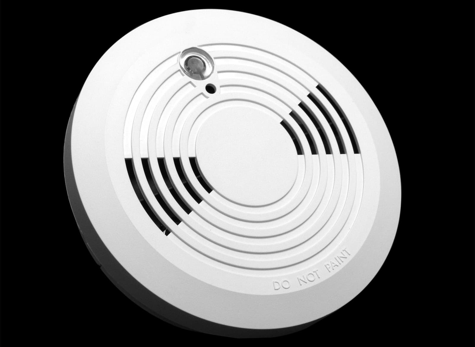
Click to zoom
Application Details
- Equipment Class
- DSC - Part 15 Security/Remote Control Transmitter
- Date of Grant
- Apr 29, 2003
- Application Purpose
- Original Equipment
- Date of Application
- Apr 29, 2003
- Equipment Note
- Smoke Detector
- Frequency Range
- 433.90000000 - 433.90000000
- Company
- Paradox Security Systems
- Country
- Canada
Documents & Files
Document Text
Text extracted from the exhibit documents filed with the FCC. Open a document above to read the original.
Users Manual
OMNSMK1-TI00PRINTED IN CANADA 03/2003 EnglishInstallationThe OMN-SMK1 should be mounted on the ceiling (or wall if necessary) in accordance with the NFPA Standard 74 (National Protection Association, Batterymarch Park, Quincy, MA 02169) outlined on reverse. The OMN-SMK1 is a wireless detector designed to work wi th the OMN-RCV3 wireless receiver and cannot be linked to other smoke detectors. The detector will not warn people who are deaf or hard of hearing. Special-purpose detectors with light or vibrating devices should be installed. For optimal detection, the unit should be m ounted as close to the center of the ceiling as possible. Always test the unit before it has been powered and after installation as outlined in “Testing the Smoke Detector”. After selecting the detector's location, drill or punch out hol es for the screws as shown in Figure 2 on reverse and follow the steps outlined below. Mounting the Detector 1. Use two of the eight keyhole slot s to mark where you will drill the mounting holes and insert the plastic wall plugs. 2. Align the mounting bracket to the wall plugs and partially insert the screws. 3. Once the mounting bracket is positioned, secure it and tighten both screws. 4. Join the detector to the mounting bracket, by aligning the lock tab to the preferred lock slot (Figure 2 on reverse), then turn counter-clockwise to lock detector into place. The mounting bracket comes with two “tamper proof” threads. Remove these threads in order to change the battery or if you wish to mount the detector to an alternative location. Unmounting the Detector Remove the detector from the mounting bracket by gently pulling the detector, then turning clockwise as shown in Figure 2 on reverse. Alternative Locations If a ceiling installation is not possible , the following alternative locations are recommended:• Ceiling mount no closer than 10cm (4 ”) from any wall or corner as shown in Figure 6 on reverse. • Wall mount (permitted by your local and state codes) between 10 and 15cm (4 to 6”) from the ceiling as shown in Figure 6 on reverse. • For sloped or peaked ceiling, try to mount the detector 1m (3.2ft) measured horizontally from the highest point of the ceiling as shown in Figure 6 on reverse. The OMN-SMK1 is designed to give early warning of developing fires by sensing smoke. It will not sense gas, heat and flame sources. Residential Installations The detector is designed for use inside a single residential unit such as a family home or apartment. For complete coverage in residential units, smoke detectors should be install ed in the following locations: • In any hallway outside bedroom areas. Additional det ectors should be installed for every bedroom area as shown in Figure 3 on reverse. • On every floor of a multi-floor home or apartment as shown in Figure 5 on reverse. • At both ends of a bedroom hallway if the hallway is more than 12m (40ft) long. • At the bottom of a basement stairwell.• At the top of the first to second floor stairwell and subsequent stairwells in multi-floored residential units. Detectors should be installed as cl ose to the center of the ceiling as possible. If this is not practi cal refer to Figure 6 on reverse for alternative locations. Non-residential Installations The detector is not intended for non-residential installations. The following locations are not recommended:• Warehouses.• Industrial or commercial buildings.• Places where people may live and work such as motels, hotels, dormitories, nursing homes, group homes even if they were previously used as family homes. • Special non-residential buildings t hat require specific fire/smoke detection systems. • Lobbies or hallways or basement s of multi-family buildings. Please refer NFPA 101, the Life Safety Code, NFPA71, 72A, 72B, 72C, 72D and 72E for smoke detector requirements for fire protection in buildings not defined as “households”. Detection Parameters Installation in the following areas may cause false alarms or impede with the detector’s ability to provide su fficient early warning. Avoid the following areas:• Dusty areas such as a garage or attic.• Areas where the temperature may fall below 4ºc (40ºF) or rise above 38ºC (100ºF). • Near fluorescent electrical lights. If this cannot be avoided, ensure a minimum installation distance of at least 1.5m (5ft). • Areas with poor ventilation or obstructions that may prevent smoke from reaching the detector. These can be the top of a peaked (sloped) roof or ceiling (Figure 5 on reve rse) and a partially or completely closed bedroom door. • Near furnaces or hot water heaters.• Humid or damp areas such as a washroom or shower. If this cannot be avoided, ensure a minimum installati on distance of at least 3m (10ft). • Near ventilated areas that may draw smoke away from the detector. • Insect-infested areas.• Areas less than 6m (20ft) away from the kitchen or cooking appliances. Never remove the batteries to stop a false alarm. Allow sufficient ventilation to reach the detector until the false alarm stops. If false alarms persist, clean out the detector. Powering the DetectorInsert the battery in the compartment located under the detector. You can insert an optional screw to secure the compartment door. Align the terminals on the end of the (alkaline) battery to those of the detector (Figure 1 on reverse). When the detector first makes contact with the battery, the LED will flicker and the horn will sound for one second. This means t hat the battery is properly connected. Close the cover and hold down the test bu tton for five seconds. The horn will emit a loud pulsating sound to indica te that the unit is working. LED Smoke Signal IndicationOnce smoke is detected, the OMN-SMK1 will emit three continuous alarms, pause and repeat this alarm pattern until the smoke condition has stopped. In addition, during an alarm, the re d LED will flicker rapidly. Upon detection of an alarm condition (s moke) the OMN-SMK1 will transmit the alarm signal every 30 sec…
Text truncated - open the document above for the full version.
Cover Letter(s)
Wednesday, March 19, 2003 Office of Engineering & Technology Federal Communications Commission Washington, D.C. 20554 Subject: Request for continuous confidentiality of technical information per Sections 0.459 and 0.457 (d) (2) (I) of CFR 47. FCC ID: KDYOMNSMK1 To Whom It May Concern: Paradox Security Systems is hereby filing this request for continuous confidentiality of the specified items submitted with the application for certification (Form 731) with proposed identifier KDYOMNSMK1 The technical documentation for which continuous confidentiality is sought is: • Schematic diagrams, PCB Layers • Components List (BOM) • Bloc Diagram • Technical Description This technical documentation is a part of the material supporting the Form 731 application for certification, which this request for confidentiality accompanies. The schematic diagrams disclose proprietary information and technical data that Paradox Security Systems would guard from its competitors and would not make available to the public. This proprietary information constitutes a trade secret and is not a part of the product documentation that would be made available to the customers of Paradox Security Systems. It would be potentially injurious to Paradox Security Systems in the development of this innovative proprietary product to make available for public disclosure the trade secret technical information specified in this request. If you have any questions or comments, please do not hesitate to contact me, Marc Bertrand Certification Manager Paradox Security Systems e-mail: [email protected]
Cover Letter(s)
Response to TCB Findings Q: Please verify if the device has been tested in the continuous transmission mode during the radiated emissions measurements Response: One sample was modified to allow for continuous transmission for the radiated measurements. Q: Please supply an operational description of the RF circuitry of the device. Response: Supplied
ID Label/Location Info
Thursday, March 20, 2003 Office of Engineering & Technology Federal Communications Commission Washington, D.C. 20554 Subject: FCC label applied on the rear side of the enclosure, (1.25” X 2”) format. FCC ID: KDYOMNSMK1 FCC ID: KDYOMNSMK1 IC: 2438A-OMNSMK1 This device complies with part 15 of the FCC Rules. Operation is subject to the following Two conditions: (1) This device may not cause harmfull interference, and (2) This device must accept any interference received, incuding interference that may cause undesired operation. MADE IN CANADA Label placement diagram: Rear side of the enclosure Marc Bertrand Certification Manager Paradox Security Systems e-mail: [email protected] FCC LABEL
Test Report
Master:PT15-Sub-C-15231 Date: November 12, 2001 Test Report: 3W06962 Applicant: Paradox Security Systems 780 Industrial Blvd. Ste-Eustache, Quebec J7R 5V3, Canada Equipment Under Test: OMN-SMK1 Smoke Detector (EUT) 433MHz Transmitter FCC ID: KDYOMNSMK1 In Accordance With: FCC Part 15, Subpart C, 15.231 Tested By: Nemko Canada Inc. 303 River Road, R.R. 5 Ottawa, Ontario K1V 1H2 Authorized By: Kevin Carr, EMC Specialist Date: 22 April 2003 Total Number of Pages: 16 Nemko Canada Inc. FCC PART 15, SUBPART C, 15.231 PROJECT NO.: 3W06962 EQUIPMENT: OMN-SMK1 Smoke Detector Page 2 of 16 Table of Contents Section 1. Summary of Test Results ...................................................................................... 3 Section 2. Equipment Under Test .......................................................................................... 5 Section 3. Transmission Requirements ................................................................................. 8 Section 4. Radiated Emissions .............................................................................................. 10 Section 5. Occupied Bandwidth ........................................................................................... 13 Section 6. Block Diagrams .................................................................................................... 15 Section 7. Test Equipment List ............................................................................................. 16 Nemko Canada Inc. FCC PART 15, SUBPART C, 15.231 PROJECT NO.: 3W06962 EQUIPMENT: OMN-SMK1 Smoke Detector Page 3 of 16 Section 1. Summary of Test Results General All measurements are traceable to national standards. These tests were conducted on a sample of the equipment for the purpose of demonstrating compliance with Part 15, Subpart C. All tests were conducted using measurement procedure ANSI C63.4-2001. Radiated emissions are made on an open area test site. A description of the test facility is on file with the FCC. THIS TEST REPORT RELATES ONLY TO THE ITEM(S) TESTED. THE FOLLOWING DEVIATIONS FROM, ADDITIONS TO, OR EXCLUSIONS FROM THE TEST SPECIFICATIONS HAVE BEEN MADE. See “ Summary of Test Data”. TESTED BY: ______________________________ DATE: 20 April 2003 Glen Westwell, Wireless Technologist Nemko Canada Inc. authorizes the above named company to reproduce this report provided it is reproduced in its entirety and for use by the company’s employees only. Any use which a third party makes of this report, or any reliance on or decisions to be made based on it, are the responsibility of such third parties. Nemko Canada Inc. accepts no responsibility for damages, if any, suffered by any third party as a result of decisions made or actions based on this report. This report applies only to the items tested. Nemko Canada Inc. FCC PART 15, SUBPART C, 15.231 PROJECT NO.: 3W06962 EQUIPMENT: OMN-SMK1 Smoke Detector Page 4 of 16 Summary Of Test Data Name of Test Para. Number Results Transmission Requirements 15.231(a) Complies Radiated Emissions 15.231(b) Complies Occupied Bandwidth 15.231(c) Complies Frequency Tolerance 15.231(d) NA Periodic Alternate Field Strength Requirements 15.231(e) NA Powerline Conducted Emissions 15.207 NA Note: This device is powered by one 9Vdc cell. Test Conditions: Indoor Temperature: 22°C Humidity: 30% Outdoor Temperature: 10°C Humidity: 35% Nemko Canada Inc. FCC PART 15, SUBPART C, 15.231 PROJECT NO.: 3W06962 EQUIPMENT: OMN-SMK1 Smoke Detector Page 5 of 16 Section 2. Equipment Under Test General Equipment Information Manufacturer: Paradox Security Systems Equipment 433MHz Tramsmitter Model No.: OMN-SMK1 Serial No.: None Date Received In Laboratory: Mar. 28, 2003 Nemko Identification No.: 1 Transmit Frequency: 433.9MHz Fixed Modulation: ASK, 100% (Pulse Carrier On Off) Emission Designator: 78K3L1D Nemko Canada Inc. FCC PART 15, SUBPART C, 15.231 PROJECT NO.: 3W06962 EQUIPMENT: OMN-SMK1 Smoke Detector Page 6 of 16 Nemko Canada Inc. FCC PART 15, SUBPART C, 15.231 PROJECT NO.: 3W06962 EQUIPMENT: OMN-SMK1 Smoke Detector Page 7 of 16 Duty Cycle Packet Pulse Length = 73.3mS 20 X Log ( 73.3 / 100 ) = -2.7 dB Nemko Canada Inc. FCC PART 15, SUBPART C, 15.231 PROJECT NO.: 3W06962 EQUIPMENT: OMN-SMK1 Smoke Detector Page 8 of 16 Section 3. Transmission Requirements Para. No.: 15.231(a) Test Performed By: Glen Westwell Date of Test: 20 April 2003 Minimum Standard: 15.231(a) Continuous transmissions such as voice, video or data transmissions are not permitted. 15.231(a)(1) A manually operated transmitter shall employ a switch that will automatically deactivate the transmitter within not more than 5 seconds after being released. 15.231(a)(2) A transmitter activated automatically shall cease transmission within 5 seconds of activation. 15.231(a)(3) Periodic transmissions at regular pre-determined intervals are not permitted. However polling or supervisory transmissions to determine system integrity of transmitters used in security or safety applications are allowed if the periodic rate of transmission does not exceed one transmission of not more than one second duration per hour for each transmitter. 15.231(a)(4) Intentional radiators which are employed for radio control purposes during emergencies involving fire, security, and safety of life, when activated to signal an alarm, may operate during the pendency of the alarm. Test Results: Complies Test Data: Compliance was determined by verification of technical specifications and a functional test on the equipment. Nemko Canada Inc. FCC PART 15, SUBPART C, 15.231 PROJECT NO.: 3W06962 EQUIPMENT: OMN-SMK1 Smoke Detector Page 9 of 16 Rationale for Compliance with Transmission Requirements 15.231(a)(1) : The transmitter is deactivated 1.1 seconds upon releasing the push button switch. 15.231(a)(2) : The transmitter deactivates 1.1 seconds after automatic activation. 15.231(a)(3) : No periodic, polling, or supervision transmissions. 15.231(a)(4) : NA Nemko Canada Inc. FCC PART 1…
Text truncated - open the document above for the full version.
Test Setup Photos
Radiated Pre-Scan Photo – FCC ID: KDYOMNSMK1 OATS Set Up Photo– FCC ID: KDYOMNSMK1
Contact Information
Applicant
Alex Chaplik(Certification Manager)
Test Firm
Nemko Canada Inc.Stuart Beck
Technical Specifications
| # | Rule Parts | Frequency Range | Power Output |
|---|---|---|---|
| 1 | 15.231 | 433.9 MHz - 433.9 MHz | - |
Other Applications from Paradox Security Systems
KDYX45
May 07, 2026Hybrid Head Unit/Console
Equipment Class
DSS - Part 15 Spread Spectrum TransmitterKDYZP2M
Dec 23, 2025Dual Input /Output Wireless Bus Expander Two Garage Door
Equipment Class
DSS - Part 15 Spread Spectrum TransmitterKDYK70M
Dec 12, 20257 inch Touchscreen Keypad
Equipment Class
DTS - Digital Transmission SystemKDYDCT12M
Nov 25, 2025Door /Window Magnetic Contact + Zone
Equipment Class
DSS - Part 15 Spread Spectrum Transmitter
KDYPGM8M
Nov 25, 2025PGM Expander
Equipment Class
DSS - Part 15 Spread Spectrum Transmitter