KDYPARAKEYRX
Paradox Security Systems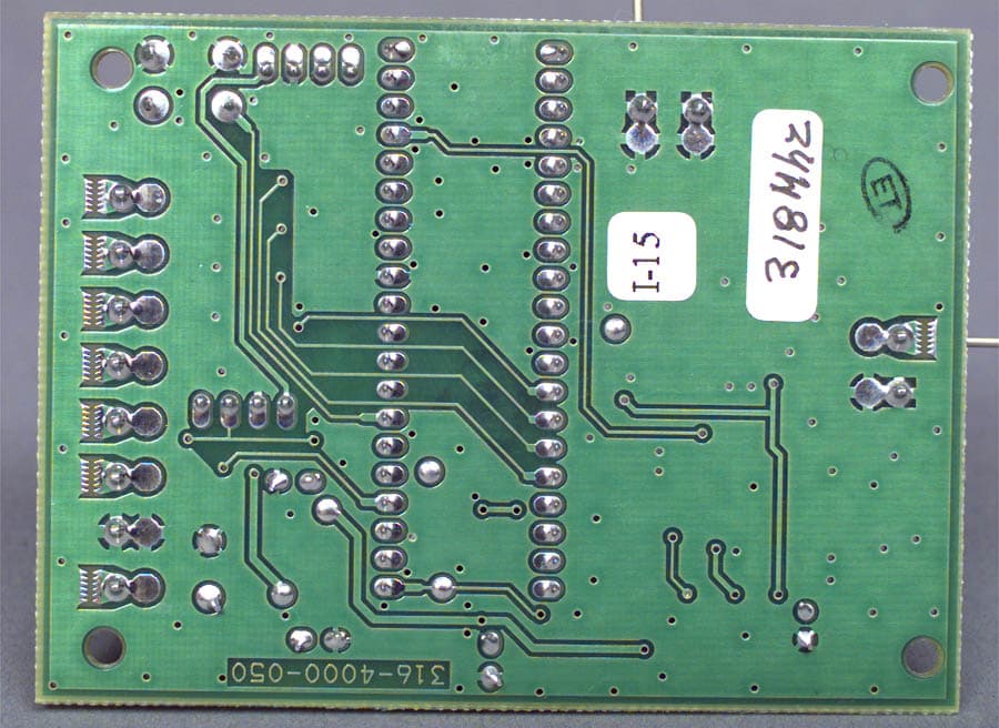
Click to zoom
Application Details
- Equipment Class
- CYY - Communications Receiver used w/Pt 15 Transmitter
- Date of Grant
- May 18, 1999
- Application Purpose
- Original Equipment
- Date of Application
- Apr 12, 1999
- Frequency Range
- 318.00000000 - 318.00000000
- Company
- Paradox Security Systems
- Country
- Canada
Documents & Files
Document Text
Text extracted from the exhibit documents filed with the FCC. Open a document above to read the original.
Users Manual
Remote Arming Module V1.10 318MHz/433MHz With KEELOQ high-security code encryption Installer’s Guide PARKEI-02 i i TABLE OF CONTENTS INTRODUCTION . . . . . . . . . . . . . . . . . . . . . . . . . . 2 1.1 Features . . . . . . . . . . . . . . . . . . . . . . . . . . . . . . . 21.2 Technical Specifications . . . . . . . . . . . . . . . . . . . . 3INSTALLATION . . . . . . . . . . . . . . . . . . . . . . . . . . . 4 2.1 Location & Mounting . . . . . . . . . . . . . . . . . . . . . . 42.2 Power & Communication . . . . . . . . . . . . . . . . . . . 4 2.2.1 With Esprit Control Panel . . . . . . . . . . . . . 4 2.2.2 Stand Alone . . . . . . . . . . . . . . . . . . . . . . . 5 2.3 Keypad . . . . . . . . . . . . . . . . . . . . . . . . . . . . . . . . 52.4 Antenna . . . . . . . . . . . . . . . . . . . . . . . . . . . . . . . . 62.5 Programmable Outputs (PGMs) . . . . . . . . . . . . . . 62.6 Hand-Held Remote Control . . . . . . . . . . . . . . . . . 72.7 System Reset . . . . . . . . . . . . . . . . . . . . . . . . . . . 8HOW TO PROGRAM . . . . . . . . . . . . . . . . . . . . . . 11 PROGRAMMING THE SYSTEM . . . . . . . . . . . . 13 4.1 Access Code Length . . . . . . . . . . . . . . . . . . . . . 134.2 Installer Code . . . . . . . . . . . . . . . . . . . . . . . . . . 134.3 User Parameters . . . . . . . . . . . . . . . . . . . . . . . . 13 4.3.1 User Access Codes . . . . . . . . . . . . . . . . 14 4.3.2 Remote Control Assignment . . . . . . . . . . 15 4.3.3 Remote Control Options . . . . . . . . . . . . . 16 4.4 Panic Output Programming . . . . . . . . . . . . . . . . 174.5 Panic Lockout Timer . . . . . . . . . . . . . . . . . . . . . 184.6 PGM Output Timing . . . . . . . . . . . . . . . . . . . . . . 184.7 Button PGM Options . . . . . . . . . . . . . . . . . . . . . 194.8 Panic Option . . . . . . . . . . . . . . . . . . . . . . . . . . . 20 1 1 INTRODUCTION The PARAKEY is a wireless remote control system that consists of a receiving module and up to eight 2 or 4-buttonremote controls (transmitters). When used in conjunctionwith any Paradox Esprit Series Control Panel , remote controls can perform actions such as remote arming anddisarming, communicating panic alarms and/or activatingprogrammable outputs (PGMs). Each remote control isassigned to a specific user and therefore, identifies the userto the control panel when used. If desired, it can be used asa stand-alone system where the remote controls will onlyactivate the on-board PGM outputs. When a button on theremote control is pressed, it will transmit an RF signal.When the PARAKEY receives this signal, it then processes the request and performs the programmed action(s). • Simple, user-friendly programming.• Supports 8 User Codes, each linked to a unique RF Code (2 or 4-button remote control). • Encrypted RF codes for additional security. Does not use DIP switch programming. • 4 programmable outputs (PGMs). • Stand-alone operation (trigger PGMs only) or in conjunction with a Paradox Esprit Series Control Panel (arm/disarm, panic & PGM activation). • Programming keypad connects directly to the Parakey Receiving Module. • Programmable Installer Code.• Software reset. 1.2.1 Receiver:Compatible Programming Keypads: (616 V4.2A & up ) (626 V4.1A & up ) DC input: 12VDC PGM outputs: 4 PGM Output 1-3 Current Rating: 30mA max. PGM Output 4 Current Rating: 5A relay Max Transmission Range: 53.34m (175 ft.) Operating Conditions: 0°C to 50°C Operating Humidity: 85% Operating Frequency: 318 or 433.92MHz Sensitivity: -110dbm 1.2.2 Remote Control:Water ResistantBattery: Lithium 3V (CR2032) Battery Life: Apprx. 2 years Power Transmission: 7mW Current Consumption: 6mA (transmission) 1.2 Technical Specifications 1.1 Features 2 3 INSTALLATION We recommend installing the receiver in a centralizedlocation on the main floor. Avoid installing the receiver inthe basement. Although, if desired, it can be installed inproximity of the control panel. When selecting aninstallation site please take into consideration that themaximum reception distance of the receiver isapproximately 54 meters (175 feet) line of sight. The circuitis static sensitive, thus take great care during handling. Avoid installing the receiving module near or in the path of strong RF fields, such as neon lights or computers. Also avoid installing the receiver on or near metal objects, circuit breaker boxes, air conditioners and heater ducts. These devices may cause interference, reducing the receiver's sensitivity. If installing the Parakey away from the control panel, mountthe Parakey Receiver Module on a wall, leaving at least 2"around the panel box to permit adequate ventilation/heatdissipation. Selecting a site that is not susceptible todrastic changes in temperature and humidity.2.2.1 With Esprit Control PanelWhen used in conjunction with any Paradox Esprit Series Control Panel , the auxiliary terminals (12V DC ) of the control panel may power the Parakey Receiving Moduleas shown in figure 3. If using an external power sourceplease ensure that the " GND " of the receiver and the power source are connected to the " AUX -" terminal of the control panel.The " GRN " and " YEL " terminals of the control panel must be connected to the " GRN " and " YEL " terminals of the Parakey Receiving Module in order to providecommunication between the modules. Alternatively, youcan use a 4-pin serial connector between the controlpanel's " SERVICE KEYPAD " connector and the Parakey Module's " PANEL " connector. 2.2.2 Stand AloneWhen used as a stand-alone system, you will need aParadox 12V DC 801 Power Supply and a 12V DC backup battery. Connect the power supply and the backupbattery as shown in figure 4.The Parakey Receiving Module is programmed using a616 or 626 Esprit LED Keypad. Connect the keypad asshown in figure 3 or 4. Alternatively, you can connect thekeypad to the Parakey Module's " PROGRAM " connector using a 4-pin serial connector. The Parakey can only be programmed using: 616 keypad version 4.2A and up or 6…
Text truncated - open the document above for the full version.
Users Manual
Remote Control Options Keys (on/off) [1] [2 ] [3 ] [4 ] [5 ] [6 ] [7 ] [8 ] Section [17] : User 1 ___ ___ ___ ___ ___ ___ ___ ___ Section [18] : User 2 ___ ___ ___ ___ ___ ___ ___ ___ Section [19] : User 3 ___ ___ ___ ___ ___ ___ ___ ___ Section [20] : User 4 ___ ___ ___ ___ ___ ___ ___ ___ Section [21] : User 5 ___ ___ ___ ___ ___ ___ ___ ___ Section [22] : User 6 ___ ___ ___ ___ ___ ___ ___ ___ Section [23] : User 7 ___ ___ ___ ___ ___ ___ ___ ___ Section [24] : User 8 ___ ___ ___ ___ ___ ___ ___ ___ OFF Key On [1] Set arming methods [2 ] see table on [3 ] next page Disabled [4 ] * Button 1 PGM Enabled Disabled [5 ] * Button 2 PGM Enabled Disabled [6 ] * Button 3 PGM Enabled Disabled [7 ] * Button 4 PGM Enabled Disabled [8 ] * Panic Enabled (simultaneously press buttons 1 and 2 to activate a panic alarm) = Button 1 = Button 2 References to button 3 & 4 refer to 4-button remote controls. 318/433MHz V1.10 PROGRAMMING CARD Press “ PROG ” button + [ ENTER ] + [ INSTALLER CODE ] + [ SECTION ] + required data + [ ENTER ] * = D EFAULT S ETTING Section Data Description [00] __/__/__/__/__/__ Installer Code * (757575) [01] __/__/__/__/__/__ User Access Code 1 [02] __/__/__/__/__/__ User Access Code 2 [03] __/__/__/__/__/__ User Access Code 3 [04] __/__/__/__/__/__ User Access Code 4 [05] __/__/__/__/__/__ User Access Code 5 [06] __/__/__/__/__/__ User Access Code 6 [07] __/__/__/__/__/__ User Access Code 7 [08] __/__/__/__/__/__ User Access Code 8 [09] Press [ ENTER ] & button 1 twice to assign RC to User 1 l [10] Press [ ENTER ] & button 1 twice to assign RC to User 2 l [11] Press [ ENTER ] & button 1 twice to assign RC to User 3 l [12] Press [ ENTER ] & button 1 twice to assign RC to User 4 l [13] Press [ ENTER ] & button 1 twice to assign RC to User 5 l [14] Press [ ENTER ] & button 1 twice to assign RC to User 6 l [15] Press [ ENTER ] & button 1 twice to assign RC to User 7 l [16] Press [ ENTER ] & button 1 twice to assign RC to User 8 l PARKEP-02 } Panic Output ProgrammingSection [25] : __ (select one digit only) ‘‘ [0] = Disabled[1] = Activate output 1 on panic alarm[2] = Activate output 2 on panic alarm * [3] = Activate output 3 on panic alarm [4] = Activate output 4 on panic alarm Panic Lockout TimerSection [26] : __ (select one digit only) ‘‘ * [0] = Disabled [1] = 30 second signal lockout on panic alarm[2] = 60 second signal lockout on panic alarm[3] = 90 second signal lockout on panic alarm[4] = 120 second signal lockout on panic alarm Key Key Key Description [1] [2 ] [3 ] ____________________________________________Off Off Off No Arming & Disarming On Off Off * Button 1 = Regular Arming Off On Off Button 2 = Regular Arming On On Off Button 1 = Regular Arming Button 2 = Regular Arming Off Off On Button 1 = Away Arming On Off On Button 1 = Away Arming Button 2 = Stay Arming Off On On Button 1 = Regular Arming Button 2 = Stay Arming On On On Button 1 = Stay Arming Section [35] : General Options OFF Key ON 4-Digit __ [1] __ * 6-Digit Access Codes PGM only __ [2] __ * Panic activates enabled PGM & sends panic command to control panel PGM Options Keys (on/off) [1] [2] [3] [4] PGM1 PGM2 PGM3 PGM4 Section [31] : Button 1 (default: [1] on) ___ ___ ___ ___ Section [32] : Button 2 (default: [2] on) ___ ___ ___ ___ Section [33] : Button 3 (default: [3] on) ___ ___ ___ ___ Section [34] : Button 4 (default: [4] on) ___ ___ ___ ___ Key ON activates corresponding PGM Key OFF disables corresponding PGM PGM Options TimingSection [27] : __ PGM 1 (select one digit only) Section [28] : __ PGM 2 (select one digit only) Section [29] : __ PGM 3 (select one digit only) Section [30] : __ PGM 4 (select one digit only) ‘‘ [0] = Latched [3] = 10 seconds [6] = 60 seconds [1] = 1 second [4] = 20 seconds [7] = 2 minutes * [2] = 5 seconds [5] = 40 seconds [8] = 4 minutes
Attestation Statements
WARNINGS NOTE: Any changes or modification not expressly approved by PARADOX SECURITY SYSTEMS could void the user’s authority to operate the equipment.
ID Label/Location Info
ABC Corporation Model No. PARAKEY318 CANADA:FCC ID: KDYPARAKEYRX This device complies with part 15 of the FCC Rules. Operation is subject to the following two conditions: (1) this device may not cause interference, and (2) this device must accept any interference, including interference that may cause undesired operation of the device. Made in Canada
Test Report
Master: ktlPT15BR Date: February 23, 1999 KTL Test Report:8R1099 Applicant:Paradox Security Systems 780 Industrial Blvd. Ste. Eustache, Quebec J7R 5V3 Equipment Under Test:PARAKEY Receiver (E.U.T.) FCC ID:KDYPARAKEYRX In Accordance With:FCC Part 15, Subpart B Radio Receivers Tested By:KTL Ottawa Inc. 3325 River Road, R.R. 5 Ottawa, Ontario K1V 1H2 Authorized By: T. Tidwell, Laboratory Manager Date: Total Number of Pages:29 KTL OttawaFCC PART 15, SUBPART B RADIO RECEIVERS PROJECT NO.: 8R01099 EQUIPMENT: PARAKEY Receiver FCC ID: KDYPARAKEYRX Page 2 of 29 TABLE OF CONTENTS Section 1. Summary of Test Results General Summary of Tests Section 2. Equipment Under Test (E.U.T.) Equipment Details Description of E.U.T. Modifications Incorporated in E.U.T. Theory of Operation Justification Exercise Program Section 3. Equipment Configuration Equipment Configuration List Inter-connection Cables Configuration of the Equipment Under Test (E.U.T.) Block Diagram Section 4. Receiver Antenna Conducted Emissions Test Conditions Test Results Receiver Antenna Conducted Plots Section 5. Radiated Emissions Test Conditions Test Results Test Data-Radiated Emissions Radiated Photographs Radiated Emissions Plots Section 6. Powerline Conducted Emissions Test Conditions Test Results Powerline Conducted Photographs Powerline Conducted Plots KTL OttawaFCC PART 15, SUBPART B RADIO RECEIVERS PROJECT NO.: 8R01099 EQUIPMENT: PARAKEY Receiver FCC ID: KDYPARAKEYRX Page 3 of 29 TABLE OF CONTENTS, continued Section 7. Sample Calculations Conducted Emissions Radiated Emissions Section 8. Block Diagrams Conducted Emissions Radiated Emissions Section 9. Test Equipment List Equipment List - Powerline Conducted Emissions Equipment List - Radiated Emissions KTL OttawaFCC PART 15, SUBPART B RADIO RECEIVERS PROJECT NO.: 8R01099 EQUIPMENT: PARAKEY Receiver FCC ID: KDYPARAKEYRX Page 4 of 29 Section 1.Summary of Test Results General: All measurements are traceable to national standards. These tests were conducted on a sample of the equipment for the purpose of demonstrating compliance with FCC Part 15, Subpart B. Measurement procedure ANSI C63.4-1992 was used for all tests. Radiated Emissions were measured on an open area test site. New SubmissionProduction Unit Class II Permissive ChangePre-Production Unit CRR Equipment Code THIS TEST REPORT RELATES ONLY TO THE ITEM(S) TESTED. THE FOLLOWING DEVIATIONS FROM, ADDITIONS TO, OR EXCLUSIONS FROM THE TEST SPECIFICATIONS HAVE BEEN MADE. See “ Summary of Test Data”. NVLAP LAB CODE: 100351-0 TESTED BY: _____________________________________ DATE: ___________________ Kevin Carr, Technologist KTL Ottawa Inc. authorizes the above named company to reproduce this report provided it is reproduced in its entirety and for use by the company’s employees only. Any use which a third party makes of this report, or any reliance on or decisions to be made based on it, are the responsibility of such third parties. KTL Ottawa Inc. accepts no responsibility for damages, if any, suffered by any third party as a result of decisions made or actions based on this report. This report applies only to the items tested. KTL OttawaFCC PART 15, SUBPART B RADIO RECEIVERS PROJECT NO.: 8R01099 EQUIPMENT: PARAKEY Receiver FCC ID: KDYPARAKEYRX Page 5 of 29 Summary Of Test Data Name Of TestPara. No.Results Antenna Conducted Emissions15.111Not Applicable Radiated Emissions15.109Complies Powerline Conducted Emissions15.107Not Applicable Footnotes For N/A’s: Test Conditions: IndoorTemperature: 21 °C Humidity:31 % OutdoorTemperature: 15 °C Humidity:31 % KTL OttawaFCC PART 15, SUBPART B RADIO RECEIVERS PROJECT NO.: 8R01099 EQUIPMENT: PARAKEY Receiver FCC ID: KDYPARAKEYRX Page 6 of 29 Section 2.Equipment Under Test (E.U.T.) Manufacturer:Paradox Security Systems Model No.:PARAKEY Serial No.:None Equipment Details Frequency Range:318 MHz Number of Channels:1 Operating Frequency(ies) of Sample:318 MHz Crystal Frequency(ies):318 MHz SAW Resonator Primary Power Requirement:12 Vdc Intermediate Frequency(ies):Not Applicable KTL OttawaFCC PART 15, SUBPART B RADIO RECEIVERS PROJECT NO.: 8R01099 EQUIPMENT: PARAKEY Receiver FCC ID: KDYPARAKEYRX Page 7 of 29 Description of E.U.T. The E.U.T. is a 318 MHz Supergenerative Receiver that connects to a home alarm system enabling remote arming and disarming. Modifications Incorporated in E.U.T. The EUT has not been modified from what is described by the brand name and unique type identification stated above. KTL OttawaFCC PART 15, SUBPART B RADIO RECEIVERS PROJECT NO.: 8R01099 EQUIPMENT: PARAKEY Receiver FCC ID: KDYPARAKEYRX Page 8 of 29 Theory of Operation The PARAKEY Receiver operates with the PARAKEY Remote Arming RF Transmitter. The receiver can use up to 8 remote transmitters. KTL OttawaFCC PART 15, SUBPART B RADIO RECEIVERS PROJECT NO.: 8R01099 EQUIPMENT: PARAKEY Receiver FCC ID: KDYPARAKEYRX Page 9 of 29 Justification The E.U.T. was configured for testing as per typical installation. Position and bundling of cables were investigated to establish maximum amplitude of emissions. The following combinations were investigated to establish worst case configuration: (1) Receiver mounted as prescribed by mounting bracket. Exercise Program The E.U.T. exercise program used during radiated and conducted testing was designed to exercise the various system components in a manner similar to typical use. Exercise Mode: (1) Receiver cohered with CW signal at 318 MHz. KTL OttawaFCC PART 15, SUBPART B RADIO RECEIVERS PROJECT NO.: 8R01099 EQUIPMENT: PARAKEY Receiver FCC ID: KDYPARAKEYRX Page 10 of 29 Section 3.Equipment Configuration Equipment Configuration List: ItemDescriptionModel No.Serial.Rev. (A)Receiver ModulePARAKEYNone Inter-connection Cables: ItemDescriptionLength (m) (1)2 Conductor Bell Wire1.5 KTL OttawaFCC PART 15, SUBPART B RADIO RECEIVERS PROJECT NO.: 8R01099 EQUIPMENT: PARAKEY Receiver FCC ID: KDYPARAKEYRX Page 11 of 29 Configuration of the Equipment Under Test (E.U.T) (A) E.U.T. DC Power Supply (1) K…
Text truncated - open the document above for the full version.
Contact Information
Applicant
Alex Chaplik(Certification Manager)
Technical Contact
Non-Technical Contact
KTL OTTAWARUBY C DULMAGE
[email protected]1-800-563-6336
Test Firm
Nemko Canada Inc.Stuart Beck
Technical Specifications
| # | Rule Parts | Frequency Range | Power Output |
|---|---|---|---|
| 1 | 15B | 318 MHz - 318 MHz | - |
Other Applications from Paradox Security Systems
KDYX45
May 07, 2026Hybrid Head Unit/Console
Equipment Class
DSS - Part 15 Spread Spectrum TransmitterKDYZP2M
Dec 23, 2025Dual Input /Output Wireless Bus Expander Two Garage Door
Equipment Class
DSS - Part 15 Spread Spectrum TransmitterKDYK70M
Dec 12, 20257 inch Touchscreen Keypad
Equipment Class
DTS - Digital Transmission SystemKDYDCT12M
Nov 25, 2025Door /Window Magnetic Contact + Zone
Equipment Class
DSS - Part 15 Spread Spectrum Transmitter
KDYPGM8M
Nov 25, 2025PGM Expander
Equipment Class
DSS - Part 15 Spread Spectrum Transmitter