KDYSR130Outdoor Wireless Siren
Paradox Security Systems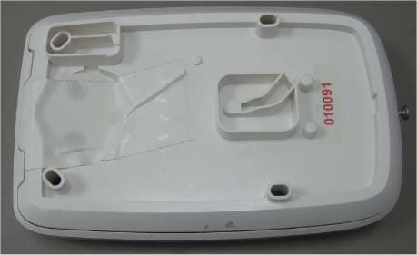
Click to zoom
Application Details
- Equipment Class
- DSR - Part 15 Remote Control/Security Device Transceiver
- Date of Grant
- Jan 13, 2015
- Application Purpose
- Original Equipment
- Date of Application
- Jan 12, 2015
- Equipment Note
- Outdoor Wireless Siren
- Frequency Range
- 433.92000000 - 433.92000000
- Company
- Paradox Security Systems
- Country
- Canada
Documents & Files
Document Text
Text extracted from the exhibit documents filed with the FCC. Open a document above to read the original.
Users Manual
ProgrammingThe following provides instructions on how to progra m your siren via a keypad or by using BabyWare. For more details on how to program, please refer to the MG/SP Programming Guide.To Program Using a KeypadTo P r o g r a m U s i n g B a b y Wa r e1. Open BabyWare and connected to your system. 2. Go to BabyWare => Add Item => Wireless Sirens. 3. Fill-in the label, location, an d serial number of the SR130. 4. Click Save. Certifications SR130: Outdoor Wireless Siren w/Built-In Strobe LightDescription The SR130 is a stand-alone, fully supervised outdoor wi reless siren with built-in strobe light and wireless transceiver. With normal use, the SR130 will function up to three years withou t the need to replace the batteries. The SR130 uses 2-way wireless communicati on, which provides continuous supervision between the panel and siren with fast response to alarm sign als within 4 seconds.The SR130 operates using three size “C” alkaline batteries. Overview Figure 1:ISR130 Back cover MG6250 MG/SP Feature Details [0801] [683] Learn Siren #1 Press and hold “Reset/Training” switch for 3 seconds after entering the section to learn the siren. WARNING: When you press the "Reset/Training" switch, the SR130 will squawk and the strobe light will flash five times to confirm registration to the panel. [0802] [684] Learn Siren #2 [0803] [685] Learn Siren #3 [0804] [686] Learn Siren #4 [0801] [687] Display Signal Strength Siren #1 Press and hold "Reset/Training" switch for 3 seconds after entering the section to display, on a K32LCD V1.3 or higher, the signal strength the panel is receiving from the siren. [0802] [688] Display Signal Strength Siren #2 [0803] [689] Display Signal Strength Siren #3 [0804] [690] Display Signal Strength Siren #4 [0811] [691] Label Siren #1 These labels are used when reporting events via e-mail through the IP100/ IP150 (MG/SP only) or SMS personal reporting (MG6250 only) and for troubleshooting purposes. Maximum 16 characters. [0812] [692] Label Siren #2 [0813] [693] Label Siren #3 [0814] [694] Label Siren #4 [0800] [695] Temporary Ta m p e r S w i tc h Deactivation for Maintenance Press the [enter] key after entering the section to deactivate tamper alarm until the cover is reinstalled or after 30 minutes. [0820] [587] Panel Supervision of Siren OFF = disabled ON = enabled (default) Option [1] Option [3] Siren #1 (OFF/ ON) The control panel supervises the presence of the SR130. If lost, the control panel will follow global supervision loss option set in the panel. Option [2] Option [4] Siren #2 (OFF/ ON) Option [3] Option [5] Siren #3 (OFF/ ON) Option [4] Option [6] Siren #4 (OFF/ ON) EN50131-4 Grade 2, Type W EN 50130-5 Class IV Certification Body: Applica Test and Certification DESIGN SR120 Outdoor 1. Siren (100dB or more) * 2. Wall tamper switch and cover tamper switch 3. Reset/Training switch 4. Tamper Switch connector 5. Battery pack (3 size “C” alkaline batteries) 6. Strobe lights 7. In-Field connector 8. Signal Strength and transmission LED 9. Antenna 10. Status LED 11. Mounting screw 12. Captive screw * Warning! High Voltage. Remove batteries before maintenance SR130-EI00Version 1.0Printed in Canada12/2014 LED FeedbackInstallation1. Write down the serial number (on the back of the unit) and location of the SR130 for later reference, to insert into BabyWare. 2. Unlock the top cover by turning the captive screw. 3. Remove the top cover from the siren. 4. Mount the SR130 siren to the wall using the mounting screws. 5. Make sure the Anti-Tamper switch is screwed into the wall. Siren with Batteries Figure 2:Remove the Cover If your siren already has batteries installed you need to: A Remove the plastic tab between the top battery terminals and the battery compartment.B Leave the covers off until you train the siren. Siren without BatteriesIf your siren does not come with the batteries then: A Insert the batteries. Make sure to place with the proper polarity. B Leave the covers off until you train the siren. 6. Reinstall the PCB cover. 7. Reinstall the siren cover and lock. Upgrading FirmwareThe SR130 firmware can be upgraded through In-Field (V3.0 or higher) using the 307USB Direct Connect Interface. Notes: a. The SR130 needs the batteries installed to upgrade the firmware. b. Ensure that the SR130 Wireless Siren is awake before beginning the firmware upgrade. To wake up the siren, press the training/reset swit ch. The siren will provide you with a 60 second delay in order to begin the update. 1. Remove the front cover see Figure 2. 2. Connect the 307USB to the In-Field co nnector (connector #8 in Figure 1). 3. Refer to the firmware upgrade instructions found at: www.paradox.com =>Software => In-Field Firmware Upgrade Instructions. Tamper SupervisionIf a tamper is detected, the SR130 sounds an alarm and the strobe light flashes for 4 minutes. The control panel follows the global supervision options set in the panel.Specifications* Only 433 MHz version is approved for FCC and ICCompatibilityFCC and Industry Canada Compliance Statement T his device complies with FCC Rules Part 15 and with Industry Cana da license exempt RSS standard(s). Operation is subject to two conditions: 1.This device may not cause harmful interference2.This device must accept any interference that may be received or that may cause undesired operation.Le présent appareil est conforme aux CNR d'Industrie Canada applicables aux appareils radio exempts de licence. L'exploitation est autorisée aux deux conditions suivantes : 1.l'appareil ne doit pas produire de brouillage, et 2.l'utilisateur de l'appareil doit accepter tout brouillage radioélectrique subi, même si le brouillage est susceptible d'en co mpromettre le fonctionnement. FCC ID: KDYSR130IC: 2438A-SR130 FCC WARNINGThis equipment has been tested and found to comply with the limits for a Class B digital device, pursuant to Part 15 of the FCC Rules. These limits are designed to provide reasonable protection against harmful interference in a re…
Text truncated - open the document above for the full version.
Cover Letter(s)
Page 1 of 1 January 4, 2015 Telefication B.V. Attn: Dept. FCC TCB Edisonstraat 12A 6902 PK ZEVENAAR The Netherlands Subject: Application for certification of an Outdoor Wireless Siren, FCC ID:KDYSR130 Dear Gentlemen, Please find attached our application for certification of an Outdoor Wireless Siren, FCC ID:KDYSR130, model name SR130, prepared in accordance with FCC Rules part 2 and part 15 subpart C section 15.231(a). The product testing and this application for certification were performed by Hermon Laboratories, which is listed by FCC, Registration Numbers 90623, 90624. The FCC Designation Number is US1003. Hermon Labs responsible person is Mr. Michael Nikishin, tel: +972 4626 8440, fax:+972 4628 8277, e-mail: [email protected]. Please send an invoice to Hermon Labs. We hope this application satisfies your requirements Sincerely yours, Nimrod Herman Certification Manager
Cover Letter(s)
Ref: Authorization Letter _ SR130_rev1.docx To: Hermon Labs Declaration of Authorization We, Paradox Security Systems 780 INDUSTRIAL BLVD ST-EUSTACHE, QC, CANADA J7R 5V3 Phone: 450-491-7444 Fax: 450-491-1095 Declare that Hermon Laboratories Ltd. Harakevet Industrial Zone Binyamina 30500 Israel is authorized to apply for Certification of the following product: Product description: Outdoor Wireless Siren Type Designation: SR130 on our behalf. Jan-01-2015 Nimrod Herman Certification Manager
Cover Letter(s)
Ref : FCC Declaration_SR130 780 boul. Industriel, St-Eustache (Montréal), Québec, Canada J7R 5V3 Tel. : (450) 491-7444 PARADOX.COM December 23 rd , 2014 To: Hermon Laboratories Attention: Mr. Michael Nikishin and Ms. Ella Pitt Manufacturer’s Declaration We, Paradox Security Systems Ltd. located in 780 Industrial Boulevard St.Eustache, Quebec J7R 5V3, Canada declare under our sole responsibility that the product Outdoor Wireless Siren SR130 is operated in 433.92 MHz and designed to comply and satisfy periodic operational requirements. The siren SR130 does not allow continuous transmitting (such as voice, video and radio control). The siren SR130 is not manually operated device. It is activated upon an intrusion, fault or any other pre-programmed initiating signal sent by the Control Panel. SR130 sends automatic supervision messages to the control panel 3 times every hour. The interval for each supervision message is randomly selected between 17 minutes and 20 minutes by the device’s software. Since, there is no periodical behavior except supervision transmissions, there are no predetermined intervals of any kind included in device’s algorithm. Nimrod Herman Certification Manager
External Photos
Paradox Security Systems Ltd. FCC ID: KDYSR130 IC:2438A-SR130 Page 1 of 3 EXTERNAL PHOTOGRAPHS This document contains 2 photographs Paradox Security Systems Ltd. FCC ID: KDYSR130 IC:2438A-SR130 Page 2 of 3 Photograph No.1 SR130 siren front view Paradox Security Systems Ltd. FCC ID: KDYSR130 IC:2438A-SR130 Page 3 of 3 Photograph No.2 SR130 siren rear side view Label with FCC ID:KDYSR130 and IC:2438A-SR130 will be located at the rear side panel. The statement according to FCC part 15 §15.19(a)(3) is placed in User Manual, page 2 (Application exhibit User_manual_26426). FCC ID:KDYSR130 IC:2438A-SR130
ID Label/Location Info
Paradox Security Systems Ltd. FCC ID:KDYSR130 IC:2438A-SR130 Page 1 of 1 Label The label shown below is affixed on the rear side panel of the siren. The label material is PVC with a permanent adhesive. Label location The label location is shown in the application exhibit “External_photos_26426” which is a subject of Short- term confidentiality according to the applicant request. The statement according to FCC part 15 §15.19(a)(3) is placed in User Manual, page 2 (Application exhibit User_manual_26426).
Internal Photos
Paradox Security Systems Ltd. FCC ID:KDYSR130 IC:2438A-SR130 Page 1 of 6 INTERNAL PHOTOGRAPHS This document contains 5 photographs Paradox Security Systems Ltd. FCC ID:KDYSR130 IC:2438A-SR130 Page 2 of 6 Photograph No.1 SR130 siren internal view Paradox Security Systems Ltd. FCC ID:KDYSR130 IC:2438A-SR130 Page 3 of 6 Photograph No.2 SR130 siren main PCB front view with antenna Paradox Security Systems Ltd. FCC ID:KDYSR130 IC:2438A-SR130 Page 4 of 6 Photograph No.3 SR130 siren main PCB front view Paradox Security Systems Ltd. FCC ID:KDYSR130 IC:2438A-SR130 Page 5 of 6 Photograph No.4 SR130 siren main PCB second side view Paradox Security Systems Ltd. FCC ID:KDYSR130 IC:2438A-SR130 Page 6 of 6 Photograph No.5 Antenna close view
Test Report
Hermon Laboratories Ltd. Harakevet Industrial Zone, Binyamina 30500, Israel Tel. +972-4-6288001 Fax. +972-4-6288277 E-mail: [email protected] Page 1 of 48 Report ID: PARRAD_FCC.26426.doc Date of Issue: 14-Dec-14 ELECTRICAL TESTING 0839.01 TEST REPORT ACCORDING TO: FCC CFR 47 Part 15 subpart C, section 15.231(a) and subpart B; RSS-210 issue 8 Annex 1, ICES-003 Issue 5:2012 FOR: Paradox Security Systems Ltd. Outdoor Wireless Siren Model:SR130 FCC ID:KDYSR130 IC:2438A-SR130 This report is in conformity with ISO/ IEC 17025. The "A2LA Accredited" symbol endorsement applies only to the tests and calibrations that are listed in the scope of Hermon Laboratories accreditation. The test results relate only to the items tested. This test report shall not be reproduced in any form except in full with the written approval of Hermon Laboratories Ltd. Report ID: PARRAD_FCC.26426.doc Date of Issue: 14-Dec-14 Page 2 of 48 Table of contents 1 Applicant information ..................................................................................................................................................... 3 2 Equipment under test attributes .................................................................................................................................... 3 3 Manufacturer information .............................................................................................................................................. 3 4 Test details .................................................................................................................................................................... 3 5 Tests summary .............................................................................................................................................................. 4 6 EUT description ............................................................................................................................................................. 5 6.1 General information ....................................................................................................................................................... 5 6.2 Test configuration .......................................................................................................................................................... 5 6.3 Support and test equipment .......................................................................................................................................... 5 6.4 Changes made in EUT .................................................................................................................................................. 5 6.5 Transmitter characteristics ............................................................................................................................................ 6 7 Transmitter tests according to 47CFR part 15 subpart C requirements ........................................................................ 7 7.1 Periodic operation requirements ................................................................................................................................... 7 7.2 Field strength of emissions .......................................................................................................................................... 11 7.3 Occupied bandwidth test ............................................................................................................................................. 30 7.4 Antenna requirements ................................................................................................................................................. 33 8 Unintentional emissions .............................................................................................................................................. 34 8.1 Radiated emission measurements .............................................................................................................................. 34 9 APPENDIX A Test equipment and ancillaries used for tests ....................................................................................... 39 10 APPENDIX B Measurement uncertainties ................................................................................................................... 40 11 APPENDIX C Test laboratory description ................................................................................................................... 41 12 APPENDIX D Specification references ....................................................................................................................... 41 13 APPENDIX E Test equipment correction factors ......................................................................................................... 42 14 APPENDIX F Abbreviations and acronyms ................................................................................................................. 48 Report ID: PARRAD_FCC.26426.doc Date of Issue: 14-Dec-14 Page 3 of 48 1 Applicant information Client name: Paradox Security Systems Ltd. Address: 780 Industriel BLVD, St-Eustache, QC, J7R 5V3, Canada Telephone: 450-491-7444 Fax: 450-491-1095 E-mail: [email protected] Contact name: Mr. Nimrod Herman 2 Equipment under test attributes Product name: Outdoor wireless siren Product type: Transceiver Model(s): SR130 Serial number: 010091 Hardware version: 331-6001-991 Software release: V1.00 Receipt date 24-Nov-14 3 Manufacturer information Manufacturer name: Paradox Security Systems Ltd. Address: 780 Industriel BLVD, St-Eustache, QC, J7R 5V3, Canada Telephone: 450-491-7444 Fax: 450-491-1095 E-Mail: [email protected] Contact name: Mr. Nimrod Herman 4 Test details Project ID: 26426 Location: Hermon Laboratories Ltd. Harakevet Industrial Zone, Binyamina 30500, Israel Test started: 24-Nov-14 Test completed: 03-Dec-14 Test specification(s): FCC 47CFR part 15, subpart C, §15.231(a), subpart B; RSS-210 …
Text truncated - open the document above for the full version.
Test Setup Photos
Paradox Security Systems Ltd. FCC ID: KDYSR130 IC:2438A-SR130 Page 1 of 5 SETUP PHOTOGRAPHS This document contains 4 photographs Paradox Security Systems Ltd. FCC ID: KDYSR130 IC:2438A-SR130 Page 2 of 5 Photograph No.1 Setup for spurious emission field strength measurements in the anechoic chamber below 30 MHz Paradox Security Systems Ltd. FCC ID: KDYSR130 IC:2438A-SR130 Page 3 of 5 Photograph No.2 Setup for carrier field strength, spurious emission field strength measurements in the anechoic chamber in 30 – 1000 MHz range Paradox Security Systems Ltd. FCC ID: KDYSR130 IC:2438A-SR130 Page 4 of 5 Photograph No.3 Setup for spurious emission field strength measurements in the anechoic chamber above 1000 MHz Paradox Security Systems Ltd. FCC ID: KDYSR130 IC:2438A-SR130 Page 5 of 5 Photograph No.4 Setup for OBW and periodic operation measurements
Contact Information
Applicant
Alex Chaplik(Certification Manager)
Technical Contact
Hermon Laboratories Ltd.Michael Nikishin
[email protected]972 4626 8440
Harakevet Industrial zone, P.O.Box 23 · Israel
Non-Technical Contact
Paradox Security SystemsNimrod Herman
[email protected]972 4850 0499
Test Firm
Hermon Laboratories Ltd.Alexander Usoskin
Technical Specifications
| # | Rule Parts | Frequency Range | Power Output |
|---|---|---|---|
| 1 | 15.231 | 433.92 MHz - 433.92 MHz | - |
Other Applications from Paradox Security Systems
KDYX45
May 07, 2026Hybrid Head Unit/Console
Equipment Class
DSS - Part 15 Spread Spectrum TransmitterKDYZP2M
Dec 23, 2025Dual Input /Output Wireless Bus Expander Two Garage Door
Equipment Class
DSS - Part 15 Spread Spectrum TransmitterKDYK70M
Dec 12, 20257 inch Touchscreen Keypad
Equipment Class
DTS - Digital Transmission SystemKDYDCT12M
Nov 25, 2025Door /Window Magnetic Contact + Zone
Equipment Class
DSS - Part 15 Spread Spectrum Transmitter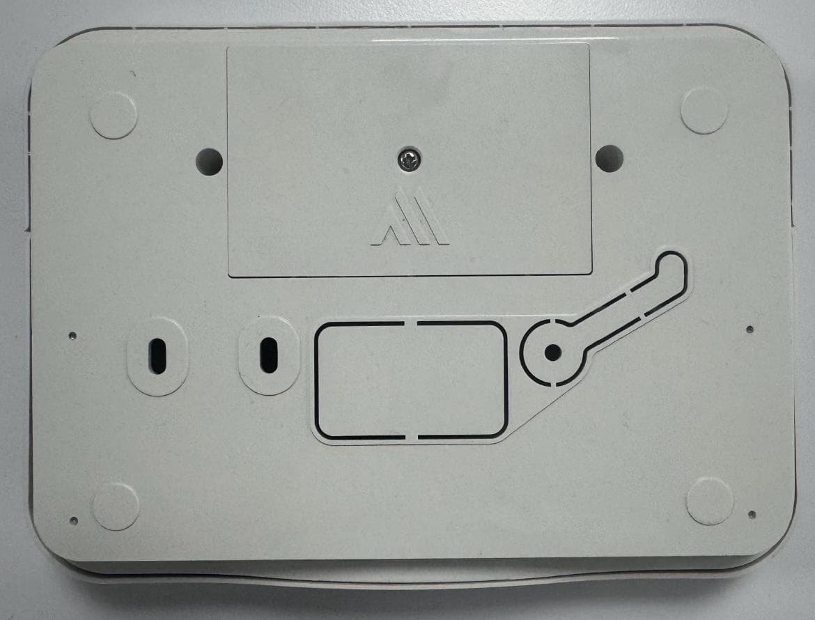
KDYPGM8M
Nov 25, 2025PGM Expander
Equipment Class
DSS - Part 15 Spread Spectrum Transmitter