KE3-3001055Max Dog Computer Collar
Radio Systems Corp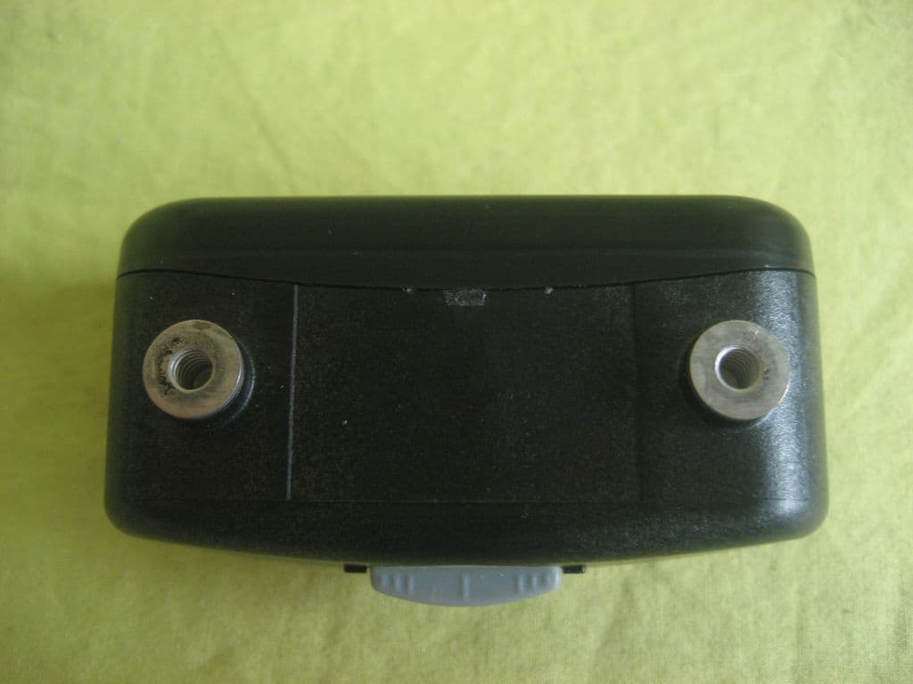
Click to zoom
Application Details
- Equipment Class
- DXX - Part 15 Low Power Communication Device Transmitter
- Date of Grant
- Mar 07, 2010
- Application Purpose
- Original Equipment
- Date of Application
- Mar 07, 2010
- Equipment Note
- Max Dog Computer Collar
- Frequency Range
- 433.92000000 - 433.92000000
- Company
- Radio Systems Corp
- Country
- United States
Documents & Files
Document Text
Text extracted from the exhibit documents filed with the FCC. Open a document above to read the original.
Users Manual
MaxDog ™ Computer Collar ® Unit Owner’s Manual www.invisiblefence.com www.invisiblefence.com 2 Congratulations on your purchase of the world’s premier pet containment solution, the Invisible Fence ® Brand. When professionally installed, the Invisible Fence® Brand pet containment system is backed with a one-year, money-back performance guarantee. The support of your Invisible Fence ® Brand Dealer gives you peace of mind that your dog remains safe at home ®. Refer to your warranty card or the back of your sales contract for complete details. Table of Contents Components ..................................................................................................................... 3 How the Systems Works .................................................................................................... 3 Operating Guide ............................................................................................................. 4 The MaxDog Computer Collar® Unit ............................................................................... 4 Fitting the MaxDog Computer Collar ® Unit ..................................................................... 4 MaxDog Computer Collar ® Power Cap Unit Status .......................................................... 4 Changing the Power Cap Unit .......................................................................................... 5 Power Cap Unit Tester ...................................................................................................... 5 Troubleshooting Guide ................................................................................................. 6 Important Warnings ..................................................................................................... 7 Battery Disposal ....................................................................................7 Compliance ...........................................................................................7 Important Precautions 1. Read and retain manuals: Read the entire Owner’s Manual and training instructions before using your new Invisible Fence® Brand pet containment system. 2. Train your pet according to the instructions in the Invisible Fence® Brand training manuals. Complete all steps before allowing your pet to run free. Do not become overly confident if your pet has become conditioned to the Invisible Fence® Brand pet containment system sooner than expected. 3. Adhere to all cautions and warnings contained in any Invisible Fence® Brand manual. 4. Do not attempt to service any Invisible Fence® Brand equipment. Refer all service to your authorized Invisible Fence® Brand Dealer. Only your authorized Invisible Fence® Brand Dealer should make adjustments to your pet containment system. Unauthorized service or repair will void the warranty. 5. All Invisible Fence® Brand pet containment systems are designed for domesticated animal use only. Never attempt to use this product for any purpose not specifically described in this manual. 6. Check the Invisible Fence® Brand transmitter periodically to make sure it is operating properly. Please refer to the chart on page 4 for proper fitting instructions. 7. Check the tightness of the MaxDog ™ Computer Collar® unit on a regular basis. Remove your pet’s MaxDog ™ Computer Collar® unit each night. This will prevent the possibility of any irritation the collar may cause to your pet’s skin. However, if this is not possible, please check the tightness of the collar each time you feed your pet by removing the collar and then replacing it back on your pet. A condition called Pressure Necrosis, which is a devitalization of the skin due to excessive and prolonged contact against the Correction Posts, may occur if the steps above are not followed. 8. If you have any questions about any aspect of your Invisible Fence® Brand pet containment system, call your Invisible Fence® Brand Dealer immediately. Dealer Name: _______________________ Dealer Phone: _______________________ www.invisiblefence.com 3 Components • MaxDog™ Computer Collar® Unit • Power Cap ® Unit • Owner’s Manual How the System Works The MaxDog ™ Computer Collar® unit is compatible with 700/800 Series Transmitters and Shields®/IFA-12 Indoor units to contain your pet within areas you choose, or teach your pet to avoid specific areas such as flower beds, gardens, or pools. The transmitter produces a signal that travels along the signal field wire and back to the transmitter to produce an Invisible Boundary® barrier. When your pet approaches the established boundary, the MaxDog ™ Computer Collar® unit generates a tone and correction to remind your pet of the boundary. With training and praise, your pet will quickly learn to avoid the established boundary. Note: A correction is a training term used to describe an action taken to discourage unwanted pet behavior. The MaxDog ™ Computer Collar® unit applies a correction when your pet crosses the boundary of an Invisible Fence® Brand electronic pet containment system. Corrections are used in combination with rewards to alter unwanted pet behavior. Your Invisible Fence® Brand pet containment system will only work when: a. The transformer is connected to the transmitter and to a functional standard electric outlet, via an approved Lightning Protection Device. All Invisible Fence® Brand pet containment systems must be grounded per the National Electric Code to be protected against lightning (North American customers only). b. The transmitter is on, connected to the signal field wire, and producing a signal along the entire length of the wire. c. The signal field wire is intact, continuous, and the transmitter’s Status Indicator light is blinking green. d. The MaxDog ™ Computer Collar® unit is correctly fitted and worn by your pet. The MaxDog ™ Computer Collar® unit must be adjusted so that both of the correction posts touch your pet’s skin. e. The Power Cap® unit in the MaxDog ™ Computer Collar® unit is good a…
Text truncated - open the document above for the full version.
Cover Letter(s)
FCC Authorization Letter Radio Systems Corporation 2010-03-01 To whom it may concern: We the undersigned, hereby authorize CTI employees Christy Chen to act on our behalf in all manners relating to application for equipment authorization, including signing of all documents relating to these matters. Any and all acts carried out by CTI employees Christy Chen on our behalf shall have the same affect as acts of our own. This authorization is valid until further written notice from Radio Systems Corporation Sincerely, Signature: 2010-03-01
Cover Letter(s)
Ersteller: U. Rodemeier Revision: 04 Erstelldatum: 03.0 8.01 Datum: 11.05.07 Seite 1 von 1 Request for Confidentiality PHOENIX TESTLAB GmbH Date: Feb. 03, 2010 Product Certification Königswinkel 10 D 32825 Blomberg RE: Certification Application FCC ID: KE3-3001055 Confidentiality Request Pursuant to Sections 0.457 and 0.459 of the Commission’s Rule, the applicant hereby requests confidential treatment of information a ccompanying this application as outlined below: • Bill of material • Operation Description • Circuit Diagram • Block Diagram (XXXXX to be replaced by Schematics, Block Diagram, etc.) The above materials contain trade secrets and proprietary information not customarily released to the public. The public disclosure of these matters might be harmful to the applicant and provide unjustified benefits to its competitors. The applicant understands that pursuant to rule 0.457, disclosure of this application and all accompanying documentation will not be made before the date of the GRANT for this application. Thank you for your attention in this matter. Applicant’s Company: Centre Testing International Corporation address : Bldg. C, Hongwei Industrial Park, Block 70, Bao’an District, Shenzhen, Guangdong, China Signature : Job Title and Dept. :EMC Engineer, EMC Lab
ID Label/Location Info
Label information: Radio Systems Corporation FCC ID: KE3-3001055 IC: 2721A-3001055 Model Name: Max Dog Computer Collar Trade Name: Invisible Fence This device complies with part 15 of the FCC Rules and Industry Canada RSS-210. Operation is subject to the following two conditions: (1) This device may not cause harmful interference, and (2) this device must accept any interference received, including interference that may cause undesired operation.
Test Report
Report No.: SZEE100126119717 Page 1 of 20 ELECTROMAGNETIC EMISSIONS COMPLIANCE REPORT INTENTIONAL RADIATOR CERTIFICATION Product Name : RIG00-12636 Model Number : Max Dog Computer Collar IC : 2721A-3001055 FCC ID : KE3-3001055 Trade Name : Invisible Fence Report Number : SZEE100126119717 Date : Mar. 02, 2010 Prepared for: Radio Systems Corporation Shenzhen Representative Office of: Radio Systems Corporation 10427 Electric Ave. Knoxville, TN 37932 USA TEL: +1 865 218 1557 FAX: +1 865 671 6854 Prepared by: CENTRE TESTING INTERNATIONAL CORPORATION Building C, Hongwei Industrial Zone, Baoan 70 District, Shenzhen, Guangdong, China TEL: +86-755-3368 3362 FAX: +86-755-3368 3385 This report shall not be reproduced, except in full, without the written approval of CENTRE TESTING INTERNATIONAL CORPORATION Building C, Hongwei Industrial Zone, Baoan 70 District, Shenzhen Standards Results RSS 210 Issue 7: 2007 RSS-Gen Issue 2: 2007 FCC Part 15C: 2009 Pass Pass Pass Report No.: SZEE100126119717 Page 2 of 20 TABLE OF CONTENTS Description Page 1. GENERAL INFORMATION......................................................................................3 2. TEST SUMMARY .....................................................................................................4 3. MEASUREMENT UNCERTAINTY ...........................................................................4 4. PRODUCT INFORMATION......................................................................................4 5. TEST EQUIPMENT ..................................................................................................4 6. 99% BANDWIDTH MEASUREMENT ......................................................................5 6.1 LIMITS..................................................................................................................5 6.2 BLOCK DIAGRAM OF TEST SETUP...................................................................5 6.3 TEST PROCEDURE..............................................................................................5 6.4 TEST RESULT......................................................................................................5 7. RADIATED EMISSIONS MEASUREMENT FOR TX ...............................................6 7.1 LIMITS..................................................................................................................6 7.2 BLOCK DIAGRAM OF TEST SETUP...................................................................6 7.3 TEST PROCEDURE..............................................................................................7 7.4 TEST RESULT......................................................................................................7 8. RADIATED EMISSIONS MEASUREMENT FOR RX.............................................13 8.1 LIMITS................................................................................................................13 8.2 BLOCK DIAGRAM OF TEST SETUP AND TEST PROCEDURE.......................13 8.3 TEST RESULT....................................................................................................13 APPENDIX 1 PHOTOGRAPHS OF TEST SETUP ......................................................15 APPENDIX 2 EXTERNAL PHOTOGRAPHS OF EUT .................................................17 APPENDIX 3 INTERNAL PHOTOGRAPHS OF EUT ..................................................18 N/A means not applicable Report No.: SZEE100126119717 Page 3 of 20 1. GENERAL INFORMATION Applicant & Address: Radio Systems Corporation Shenzhen Representative Office of: Radio Systems Corporation 10427 Electric Ave. Knoxville, TN 37932 USA Manufacturer & Address: Dongguan Staci Industrial company limited Plainvim Industrial Park, Zhongxing Avenue, Dongkeng Town, Dongguan City, Guangdong, China Equipment Under Test: RIG00-12636 Model Name: Max Dog Computer Collar IC: 2721A-3001055 FCC ID: KE3-3001055 TX Frequency: 433.92MHz RX Frequency: 10.7kHz & 7.25kHz Product Design Information: The EUT is a low power transmitter, and it complies in the complete frequency band including fundamental emission with FCC part15.209 and General Field Strength Limits in Section 2.2 of RSS-210. Trade Name: Invisible Fence Serial Number: N/A Technical Data: DC 3V Date of test: Jan. 26, 2010 to Mar. 02, 2010 The above equipment was tested by Centre Testing International Corporation for compliance with the requirements set forth in the RSS 210, RSS-Gen, FCC Part15 Section 15.209 and the measurement procedure according to IC requirements and ANSI C63.4. The test results of this report relate only to the tested sample identified in this report. Prepared by : Christy Chen Reviewed by : Louisa Lu Approved by : Jim Zhang Mana ger Date : Mar. 02, 2010 Report No.: SZEE100126119717 Page 4 of 20 2. TEST SUMMARY Clause Test Item Rule Result 6 99% bandwidth RSS-Gen 4.6.1 PASS 7 Radiated Emission RSS-210 Table 2, Table 3 & FCC Part15.209 (a) PASS Note: The power supply of EUT is by battery. 3. MEASUREMENT UNCERTAINTY This uncertainty represents an expanded uncertainty expressed at approximately the 95% confidence level using a coverage factor of k=2. Measurement items Uncertainty Radiated Emissions 4.6 dB 4. PRODUCT INFORMATION Items Description Rating DC 3V Equipments Class Low Power Transmitter Modulation OOK Frequency Range 433.92MHz Channel Number 1 Antenna Integral PCB Antenna 5. TEST EQUIPMENT Equipment Manufacturer Model NumberSerial Number Due Date Receiver R&S ESCI 100435 08/25/2010 Spectrum Analyzer Agilent E4443A MY45300910 01/19/2011 Biconilog Antenna ETS-LINGREN 3142C 920250 01/19/2011 Horn Antenna ETS-LINDGREN 3117 00057407 06/07/2010 Loop Antenna ETS-LINDGREN 6502 00071730 09/22/2010 Multi device Controller ETS-LINGREN 2090 00057230 01/19/2011 3M Chamber & Accessories ETS-LINDGREN FACT-3 N/A 01/19/2011 Preamplifier(9kHz-1GHz) Agilent 11909A 186871 08/25/2010 Report No.: SZEE100126119717 Page 5 of 20 6. 99% BANDWIDTH MEASUREMENT 6.1 LIMITS No limits. 6.2 BLOCK DIAGRAM OF TEST …
Text truncated - open the document above for the full version.
Contact Information
Applicant
Deborah J. LeMaster(Regulatory Compliance Specialist)
Test Firm
PHOENIX TESTLAB GmbHHolger Bentje
Technical Specifications
| # | Rule Parts | Frequency Range | Power Output |
|---|---|---|---|
| 1 | 15C | 433.92 MHz - 433.92 MHz | - |
Other Applications from Radio Systems Corp

KE3-PIF150-2
Jun 18, 2026Stay & Play Wireless Fence
Equipment Class
DCD - Part 15 Low Power Transmitter Below 1705 kHz
KE3-3003841
Jun 05, 2026PetSafe HydroSphere 60 oz Cordless Fountain
Equipment Class
FDS - Part 15 Field Disturbance Sensor
KE3-3003832
Apr 08, 2026GPS Tracker Collar
Equipment Class
DTS - Digital Transmission System
KE3-3003791
Jul 01, 2024MURS radio device
Equipment Class
TNB - Licensed Non-Broadcast Station Transmitter
KE3-3003803
Apr 06, 2024Dog Training Collar
Equipment Class
DSC - Part 15 Security/Remote Control Transmitter