KE3-3001070WIRELESS TRANSMITTER
Radio Systems Corp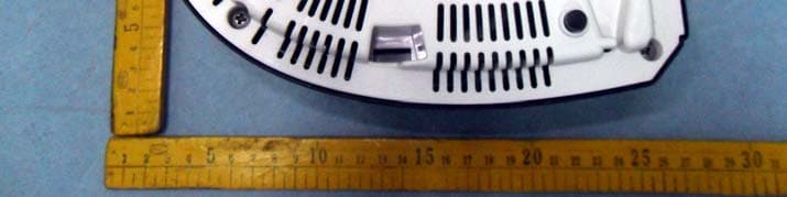
Click to zoom
Application Details
- Equipment Class
- DCD - Part 15 Low Power Transmitter Below 1705 kHz
- Date of Grant
- Jan 26, 2011
- Application Purpose
- Original Equipment
- Date of Application
- Jan 25, 2011
- Equipment Note
- WIRELESS TRANSMITTER
- Frequency Range
- 0.01870000 - 0.01870000
- Company
- Radio Systems Corp
- Country
- United States
Documents & Files
Document Text
Text extracted from the exhibit documents filed with the FCC. Open a document above to read the original.
Users Manual
stay + play wireless fence ™ operating and training guide Model Number PIF00-12917 PLEASE READ THIS ENTIRE GUIDE BEFORE BEGINNING 2 1-800-732-2677 Important Safety Information Explanation of Attention Words and Symbols used in this guide This is the safety alert symbol. It is used to alert you to potential personal injury hazards. Obey all safety messages that follow this symbol to avoid possible injury or death. WARNING indicates a hazardous situation which, if not avoided, could result in death or serious injury. CAUTION, used without the safety alert symbol, indicates a hazardous situation which, if not avoided, could result in harm to your pet. NOTICE is used to address safe use practices not related to personal injury. • Not for use with aggressive dogs. Do not use this product if your dog is prone to aggressive behavior. Aggressive dogs can cause severe injury or death to their owners and others. If you are not sure that this product is right for your dog, please talk to your veterinarian or a certifi ed trainer. • Risk of electric shock. Use the Fence Transmitter indoors in dry location only. • This PetSafe ® Stay + Play Wireless Fence ™ is NOT a solid barrier. The system is designed to act as a deterrent to remind pets by Static Correction to remain in the boundary established. It is important that you reinforce training with your pet on a regular basis. Since the tolerance level to Static Correction varies from pet to pet, Radio Systems ® Corporation CANNOT guarantee that the system will, in all cases, keep a pet within the established boundary. Not all pets can be trained to avoid crossing the boundary! Therefore, if you have reason to believe that your pet may pose a danger to others or harm himself if he is not kept from crossing the boundaries, you should NOT rely solely upon the PetSafe ® Stay + Play Wireless Fence ™ to confi ne your pet. Radio Systems ® Corporation shall NOT be liable for any property damage, economic loss or any consequential damages, sustained as a result of any animal crossing the boundary. • Proper fi t of the collar is important. A collar worn for too long or made too tight on the pet’s neck may cause skin damage. Ranging from redness to pressure ulcers; this condition is commonly known as bed sores. - Avoid leaving the collar on the dog for more than 12 hours per day. - When possible reposition the collar on the pet’s neck every 1 to 2 hours. - Check the fi t to prevent excessive pressure; follow the instructions in this manual. - Never connect a lead to the electronic collar; it will cause excessive pressure on the contacts. - When using a separate collar for a lead, don’t put pressure on the electronic collar. - Wash the dog’s neck area and the contacts of the collar weekly with a damp cloth. - Examine the contact area daily for signs of a rash or a sore. - If a rash or sore is found, discontinue use of the collar until the skin has healed. - If the condition persists beyond 48 hours, see your veterinarian. - For additional information on bed sores and pressure necrosis, please visit our website. www.petsafe.net 3 These steps will help keep your pet safe and comfortable. Millions of pets are comfortable while they wear stainless steel contacts. Some pets are sensitive to contact pressure. You may fi nd after some time that your pet is very tolerant of the collar. If so, you may relax some of these precautions. It is important to continue daily checks of the contact area. If redness or sores are found, discontinue use until the skin has fully healed. • You may need to trim the hair in the area of the Contact Points. Never shave the dog’s neck; this may lead to a rash or infection. • Always remove your dog’s Receiver Collar before performing any Transmitter testing. • The Receiver Collar should not be on your dog when the system is tested. Your pet may receive an unintended correction. • The Boundary Width of the system must be tested whenever an adjustment is made to the containment fi eld to prevent unintended corrections to your pet. • If you use a collar and leash for training, be sure the extra collar does not put pressure on the contact points. • Never remove power from the system when the collar is on the pet. This may activate the Receiver Collar. • Radio Systems ® Corporation recommends the use of an Uninterruptible Power Supply (UPS) for use with your wireless fence. Should the power go out at your home, your pet will be unprotected. Power outages can be unpredictable, and the use of a UPS will provide you with some time to properly restrain your pet. In rare instances, if your pet is near the boundary at the time when the power fails, it is possible that your pet will receive a correction. This correction will stop after a 15 second timeout period has been reached. This is due to the operation of the collar: the collar is activated by the absence of the containment signal. While results will vary depending on the UPS manufacturer’s specifi cations the following are typical examples to guide your choice of UPS: • Using a 400 VA UPS a consumer should expect 1 hour of backup time. • Using a 900 VA UPS a consumer could expect 4 hours of backup time. If settings below maximum fence size are used, additional backup time will result. At minimum fence size settings backup time may be more than two times the backup time estimated at maximum fence size. • To prevent an unintended correction, after the Boundary Flags have been placed, be sure to set the static correction on the Receiver Collar back to level 1 tone only. • Do not charge your Receiver Collar every night. Charging too often can reduce battery life. Charge your Receiver Collar when the Receiver Indicator Light blinks yellow; or when the light blinks red. • Do not place anything on the top of the Transmitter or cover any ventilation holes. This may overheat the Transmitter and cause early transmit failure. 4 1-800-732-2677 Thank you for choosing PetSafe ® brand. You and your pet deserve a…
Text truncated - open the document above for the full version.
Cover Letter(s)
Radio Systems Corp Jan. 03, 2011 Federal Communications Commission Authorization and Evaluation Division Confidentiality Request regarding application for certification of FCC ID: KE3-3001070. Pursuant to Sections 0.457 and 0.459 of the Commission’s Rules, we hereby request confidential treatment of information accompanying this application as outlined below: Exhibit Type File Name Block Diagram KE3-3001070_BlockDiagram.pdf Schematics KE3-3001070_SchematicDiagram.pdf Circuit Description KE3-3001070_CircuitDescription.pdf The above materials contain trade secrets and proprietary information not customarily released to the public. The public disclosure of these materials may be harmful to the applicant and provide unjustified benefits to its competitors. The applicant understands that pursuant to Section 0.457 of the Rules, we are aware that the exhibits listed above have publicly available since the date the grant was issued. Sincerely, Radio Systems Corp ---------------------------------------------------------- Clifton Brick (Product Safety and Regulatory Manager)
Cover Letter(s)
Radio Systems Corp Letter of Authorization FCC ID: KE3-3001070 Jan. 03, 2011 Federal Communications Commission Authorization and Evaluation Divisoin 7435 Oakland Mills Road Columbia, MD 21046 To Whom It’s My Concern: We, the undersigned,hereby Authorize Anbotek Compliance Laboratory Limited (Daniel Zhu) on our behalf, to apply to the Federal Communications Commission on our equipment. Any and all acts carried out by Anbotek Compliance Laboratory Limited (Daniel Zhu). On our behalf shall have the same effect as acts of our own. This Authorization expires on Jan. 31, 2011 This is to advise that we are in full compliance with the Anti-Drug Abuse Act. We, Radio System s Corp, are not subject to a denial of federal benefits pursuant to section 5301 of the Anti-Drug Abuse Act of 1988.21 USC835a, and no party to the application is subject to a denial of federal benefits pursuant to that section. Sincerely, C lifton Brick (Product Safety and Regulatory Manager)
External Photos
FCC ID: KE3-3001070 Page 16 o f 19 Anbotek Compliance Laboratory Limited Report No. 201012762F APPENDIX I (EXTERNAL PHOTOS) Figure 1 The EUT-Front View Figure 2 The EUT- Back View FCC ID: KE3-3001070 Page 17 o f 19 Anbotek Compliance Laboratory Limited Report No. 201012762F Figure 3 PCB of the EUT-Front View
ID Label/Location Info
The world leader in pet training products RSC Part #: 402-6215/1 Date: 12-6-10 Drawn By: JC Material: .008 Rigid white vinyl, .001 polyester over-lamination UL recognized Color: BLACK Printing: WHITE Model #: 300-1070 Description: Label model / FCC / CE Program used: AI CS5 NOTES: 1. Place date label 402-587 in location indicated. 2. Do not print dimensions. (For placement only) 3. SCALE: 1 to 1 4. Tolerance = +/-.010” 65mm 45mm PLACE DATE LABEL 402-587 IN THIS LOCATION AT FINAL ASSEMBLY 402-6215/1 FOR USE ONLY WITH WIRELESS FENCE RECEIVERS. WARNING: Risk of fire or electric shock. Connect only to UL listed Class 2 DC Power Supply. Radio Systems ® Corp. adapter part no. 650-627. Input voltage: 24 VDC, 1.5 A; Polarity: CAUTION: Risk of electric shock. Install transmitter indoors. Do not expose to rain. This device complies with part 15 of the FCC Rules. Operation is subject to the following two conditions: (1) This device may not cause harmful interference, and (2) This device must accept any interference received, including interference that may cause undesired operation. UTILISER SEULEMENT AVEC LES COLLIERS RÉCEPTEURS SANS FIL. AVERTISSEMENT: Risque d'incendie ou de choc électrique. Brancher seulement à un bloc d'alimentation de classe 2 qualifié UL. Radio Systems ® Corporation Numéro de pièce de l'adaptateur: 650-627. Tension d'alimentation: 24 VDC, 1.5 amp; Polarité: MISE EN GARDE: Risque de choc électrique. Le transmettre doit être installé à l'intérieur et ne doit pas être exposé à la pluie. Cet appareil est conforme à la partie 15 des règles FCC. Le fonctionnement est sujet aux conditions suivantes: (1) Cet appareil ne causera aucun brouillage préjudiciable, et (2) Cet appareil doit accepter tout brouillage reçu, incluant le brouillage pouvant causer un fonctionnement inopportun. 300-1070 MFG. DATE / Date de fab. Radio Systems ® Corporation Covered by US Patents / Couvert par les brevets des États-Unis portant les numéros: 6,879,300; 7,142,167 FCC ID: KE3-3001070 IC: 2721A-3001070
ID Label/Location Info
The proposed Label Location on EUT Proposed FCC ID Label Location Proposed Label Location on EUT The EUT-Bottom View/Proposed FCC ID Label Location
Internal Photos
FCC ID: KE3-3001070 Page 18 o f 19 Anbotek Compliance Laboratory Limited Report No. 201012762F APPENDIX II (INTERNALPHOTOS) Figure 4 The EUT-Inside View Figure 5 PCB of the EUT-Front View FCC ID: KE3-3001070 Page 19 o f 19 Anbotek Compliance Laboratory Limited Report No. 201012762F Figure 6 PCB of the EUT-Back View
Test Report
FCC ID: KE3-3001070 Page 1 o f 21 Anbotek Compliance Laboratory Limited Report No. 201012762F DECLARATION OF CONFORMITY On Behalf of Radio Systems Corporation Wireless Transmitter Model No.:300-1070 Prepared for : Radio Systems Corporation Address : 10427 Electric Ave., Knoxville, TN 37932 USA Tel: +1 865-218-1557 Fax: +1 865-218-1557 Prepared By : Anbotek Compliance Laboratory Limited Address : 1/F, 1 /Build, SEC Industrial Park, No. 4 Qianhai Road, Nanshan District, Shenzhen, 518054, China Tel: (86) 755-26014771 Fax: (86) 755-26014772 Report Number : 201012762F Date of Test : Dec. 21~25, 2010 Date of Report : Dec. 29, 2010 FCC ID: KE3-3001070 Page 2 o f 21 Anbotek Compliance Laboratory Limited Report No. 201012762F TABLE OF CHONTENTS Description Page Test Report Verification 1. GENERAL INFORMATION ............................................................................................................... 4 1.1. Description of Device (EUT) ..........................................................................................................................4 1.2. Description of Test Facility.............................................................................................................................5 1.3. Measurement Uncertainty ...............................................................................................................................5 2. MEASURING DEVICE AND TEST EQUIPMENT .......................................................................... 6 3. TEST PROCEDURE ............................................................................................................................. 7 4. POWER LINE CONDUCTED MEASUREMENT ............................................................................ 8 4.1. Block Diagram of Test Setup ..........................................................................................................................8 4.2. Power Line Conducted Emission Measurement Limits (FCC Part 15 15.207)...............................................8 4.3. Configuration of EUT on Measurement..........................................................................................................8 4.4. Operating Condition of EUT...........................................................................................................................8 4.5. Test Procedure.................................................................................................................................................9 4.6. Power Line Conducted Emission Measurement Results.................................................................................9 5. RADIATED EMISSION MEASUREMENT..................................................................................... 12 5.1. Radiated Emission Limits .............................................................................................................................12 5.2. Test Procedure...............................................................................................................................................12 5.3. Test Setup......................................................................................................................................................13 5.4. Test Results (Below 30MHz) ........................................................................................................................14 5.5. Test Results (Between 30-1000MHz) ...........................................................................................................14 6. PHOTOGRAPH ................................................................................................................................... 17 6.1. Photo of Power Line Conducted Emission Test............................................................................................17 6.2. Photo of Radiated Emission Test ..................................................................................................................17 FCC ID: KE3-3001070 Page 3 o f 21 Anbotek Compliance Laboratory Limited Report No. 201012762F TEST REPORT VERIFICATION Applicant : Radio Systems Corporation Manufacturer : Golden Regent Electronics Industrial Ltd. EUT : Wireless Transmitter Model No. : 300-1070 Rating : DC 24V via AC/DC Adapter Trade Mark : PetSafe Measurement Procedure Used: FCC Rules and Regulations Part 15 Subpart C 15.207&15.209-2010 & FCC / ANSI C63.4-2009 The device described above is tested by Anbotek Compliance Laboratory Limited To determine the maximum emission levels emanating from the device. The maximum emission levels are compared to the FCC Part 15 Subpart C limits both radiated and conducted emissions. The measurement results are contained in this test report and Anbotek Compliance Laboratory Limited Is assumed full responsibility for the accuracy and completeness of these measurements. Also, this report shows that the Equipment Under Test (EUT) is to be technically compliant with the FCC requirements. This report applies to above tested sample only. This report shall not be reproduced in part without written approval of Anbotek Compliance Laboratory Limited Date of Test : Dec. 21~25, 2010 Prepared by : (Engineer/ Well Wang) Reviewer : (Project Manager/ Coco Xiang) Approved & Authorized Signer : (Manager/ Tom Chen) FCC ID: KE3-3001070 Page 4 o f 21 Anbotek Compliance Laboratory Limited Report No. 201012762F 1. GENERAL INFORMATION 1.1. Description of Device (EUT) Description : Wireless Transmitter Model Number : 300-1070 Test Power Supply : 120V~, 60Hz for Adapter Adapter : SWITCH MODE POWER SUPPLY Model No.: ITC-24V1.5C Input: 100V-240V~, 50/60Hz, 1.0A max Output: 24V 1.5A CE, FCC, C-TICK, ETL Frequency : 18.7KHz Applicant : Radio Systems Corporation Address : 10427 Electric Ave., Knoxville, TN 37932 USA Manufacturer : Golden Regent Electronics Industrial Ltd. Address :Huangjinhu Management District, Qishi Town, Dongguan City, Guangdong Province, China Date …
Text truncated - open the document above for the full version.
Contact Information
Applicant
Deborah J. LeMaster(Regulatory Compliance Specialist)
Test Firm
Shenzhen Anbotek Compliance Laboratory LimitedDaniel zhu
[email protected]86-755-26014771
Technical Specifications
| # | Rule Parts | Frequency Range | Power Output |
|---|---|---|---|
| 1 | 15C | 0.0187 MHz - 0.0187 MHz | - |
Other Applications from Radio Systems Corp

KE3-PIF150-2
Jun 18, 2026Stay & Play Wireless Fence
Equipment Class
DCD - Part 15 Low Power Transmitter Below 1705 kHz
KE3-3003841
Jun 05, 2026PetSafe HydroSphere 60 oz Cordless Fountain
Equipment Class
FDS - Part 15 Field Disturbance Sensor
KE3-3003832
Apr 08, 2026GPS Tracker Collar
Equipment Class
DTS - Digital Transmission System
KE3-3003791
Jul 01, 2024MURS radio device
Equipment Class
TNB - Licensed Non-Broadcast Station Transmitter
KE3-3003803
Apr 06, 2024Dog Training Collar
Equipment Class
DSC - Part 15 Security/Remote Control Transmitter