KE3-3002511WIRELESS FLEX TRANSMITTER
Radio Systems Corp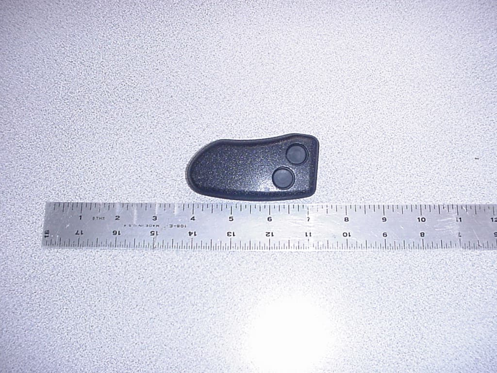
Click to zoom
Application Details
- Equipment Class
- DXX - Part 15 Low Power Communication Device Transmitter
- Date of Grant
- Feb 09, 2012
- Application Purpose
- Original Equipment
- Date of Application
- Feb 09, 2012
- Equipment Note
- WIRELESS FLEX TRANSMITTER
- Frequency Range
- 2402.00000000 - 2402.00000000
- Company
- Radio Systems Corp
- Country
- United States
Documents & Files
Document Text
Text extracted from the exhibit documents filed with the FCC. Open a document above to read the original.
Users Manual
Stance Analyzer VET Therapy www.petsafevet.com VET Therapy 2 www.petsafevet.com Important Safety InformatIon explanatIon of attentIon WordS and SymbolS uSed In thIS guIde This is the safety alert symbol. It is used to alert you to potential personal injury hazards. Obey all safety messages that follow this symbol to avoid possible injury or death. WARNING indicates a hazardous situation which, if not avoided, could result in death or serious injury. CAUTION, used without the safety alert symbol, indicates a hazardous situation which, if not avoided, could result in harm to your pet. NOTICE is used to address safe use practices not related to personal injury. Do not plug the Stance Analyzer into the same electrical outlet as the computer it will be connected to. Do not place a pet on the Stance Analyzer without the pad in place. Toe and toe nails may become stuck in the seam or edge of the Stance Analyzer. RISK OF EXPLOSION IF BATTERY IS REPLACED BY AN INCORRECT TYPE. DISPOSE OF USED BATTERIES ACCORDING TO THE INSTRUCTIONS. The RECEIVER SHOULD BE PLACED IN A SAFE PROTECTED AREA, where it will not be dropped or fall. Do not immerse any part of the unit in water. Do not pour water directly on any part of the unit. Thank you for choosing the PetSafe Vet Therapy Stance Analyzer. The Stance Analyzer is designed to help veterinarians and vet professionals accurately measure standing lameness and assess treatment effectiveness. Software updates for this product and support are available at www.petsafevet.com. Stance Analyzer www.petsafevet.com 3 hoW It WorkS The Stance Analyzer works when a pet is placed on the device, with one leg in each quadrant of the unit. The unit then quickly measures the pet’s percentage of weight distribution in each leg, center of gravity and stability. A snap shot of the pet’s stance is taken through a remote control or directly through the Stance Analyzer software. The Stance Analyzer provide veterinarians with data to diagnose standing lameness and track treatment effectiveness overtime. The software allows printing of the graphs to share with pet owner’s to further demonstrate the patient’s progress. The Stance Analyzer is effective for pet’s weight X lbs up to XXX lbs. ComponentS 1. Stance Analyzer 2. Software CD 3. Stance Analyzer Remote 4. Power cord 5. USB receiver connector cord 6. Stance Analyzer base pad reQuIrementS PC — XP or above for software Screen Resolution — At least 1024x768 for optimum performance Internet Connection (Recommended) dISplay defInItIonS Weight Distribution – This graph at the top left graph on your screen displays the percentage of weight each of the patient’s limbs is baring (Left Front, Right Front, Left Rear, Right Rear). This is a snap shot view based on the most recent sample. Center of Gravity Chart – This graph, located on the upper right portion of the screen, displays your patient’s Center of Gravity. This snap-shot reading is based on the most recent sample. Stability Graph – The Stability Graph, on the bottom right of the Center of Gravity Chart, shows data collected over time. This graph reports the change in stability of your patient as collected in your most recent Stability Test. Captured Samples – The Captured Samples Chart, on the right of the Weight Distribution Chart, shows samples collected. The most recent samples are displayed. Scroll down to view older samples. Weight Distribution History Tab – This tab, graphs the patient’s Weight Distribution over time (visit-to-visit), which shows your patient’s progress. To the right of the history is a graphical representation on the current average for comparison. VET Therapy 4 www.petsafevet.com SettIng up the StanCe analyZer Choose a level location for the Stance Analyzer. It should be within 5-6 feet of a computer. Plug the Stance Analyzer into a standard wall outlet. Ensure the base pad is on the unit, with the PetSafe logo at the top of the unit. The pad is water resistant and can be cleaned with a damp cloth and every day standard cleaning supplies. Do not plug the Stance Analyzer into the same electrical outlet as the computer it will be connected to. Do not place a pet on the Stance Analyzer without the pad in place. Toe and toe nails may become stuck in the seam or edge of the Stance Analyzer. Do not immerse any part of the unit in water. Do not pour water directly on any part of the unit. loadIng the StanCe analyZer SoftWare Important: Do not connect the Stance Analyzer to your computer until after the software has loaded. 1. Insert the PetSafe Stance Analyzer Start-Up CD into your computer device. 2. The Installation Wizard will walk you through the installation process. This window will open automatically. If your CD does not run automatically, open My Computer and run the Set-Up file. 3. Attach the USB connector found on the Stance Analyzer to your computer. The USB connected is attached to the Receiver Connector. The RECEIVER SHOULD BE PLACED IN A SAFE PROTECTED AREA, where it will not be dropped or fall. 4. Depending on the prior configuration of the computer, the computer will likely prompt you for driver software for the USB device. Choose the selection indicating Windows should choose the best option. This will occur twice (requires two drivers). 5. After the driver software installs, open the PetSafe Stance Analyzer Software. Click on the PetSafe Stance Analyzer Icon on your Desktop. 6. The Stance Analyzer is now ready. remote Control A remote control is provided for the Stance Analyzer. This captures stance data for a patient without having to the step away from the patient. It will be a more accurate and quick data capture. The remote control may need to be paired with the Stance Analyzer. Stance Analyzer www.petsafevet.com 5 remote paIrIng proCedure 1. Hold programming button (in the electronics Box) for ~ 1 second. 2. Green light will flash. 3. Press either remote button twice (separated by ~ 1 second). 4. When accepted, the Green light will flash ra…
Text truncated - open the document above for the full version.
Cover Letter(s)
10427 Electric Ave Knoxville, TN. 37932 865-777-5404 www.petsafe.net AGENCY AGREEMENT Federal Communications Commission Date: April 18, 2011 P.O. Box 429 Columbia, MD 21045 Gentlemen: By signature below, we hereby appoint US Tech employees Sandi McEnery, Alan Ghasiani, and George Yang to act as our agents with regard to all FCC equipment authorizations. This appointment will remain in effect until otherwise notified. I further certify by signature below that no party (per 47 CFR 1.2002(b)) to the application is subject to a denial of Federal benefits, including FCC benefits, pursuant to Section 5301 of the Anti-Drug Abuse Act of 1988, 21 U.S.C. 853(a). This appointment includes the authority to complete FCC Form 731 on our behalf and sign the application as an authorized agent. This appointment also includes the authority to complete and sign any confidentiality requests as an authorized agent on our behalf. Clifton P. Brick Product Safety and Regulatory Manager (FCC contact of record as of this date) Date: 4/18/2011
Cover Letter(s)
FCC Confidentiality Request February 3, 2012 Timco Engineering PO Box 370 Newberry, FL 32669 RE : FCC ID: KE3-3002511 Dear Applications Examiner: With regards to the exhibits submitted in support of the application for FCC ID: KE3-3002511, please classify the following as confidential under the provision of 47 CFR 0.459: -Schematics - File Name: 12-0016.RadioSystems.STANCE.Confidential Schematics.pdf - Block Diagram – File Name: 12-0016.RadioSystems.STANCE.Confidential Block Diagram.pdf -Operational Description – File Name: 12-0016.Radio Systems.STANCE.Confidential ToO.pdf These exhibits contain technical information that Radio Systems Corp. deems to be sensitive and proprietary. Therefore this information cannot be published. If this information were to be made public it could be used to the disadvantage of the applicant in the marketplace. Sincerely, Sandi McEnery US Tech (Authorized Agent for Radio Systems Corp.) 3505 Francis Circle Alpharetta, GA 30004 PH: 770-740-0717 Fax: 770-740-1508 www.ustech-lab.com
External Photos
FCC ID: KE3-3002511 IC: 2721A-3002511 UST Project No.: 12-0016 Date: February 2, 2012 Model: Stance Analyzer Customer: Radio Systems Corporation Page 1 of 6 External Photographs EUT Front FCC ID: KE3-3002511 IC: 2721A-3002511 UST Project No.: 12-0016 Date: February 2, 2012 Model: Stance Analyzer Customer: Radio Systems Corporation Page 2 of 6 EUT Back FCC ID: KE3-3002511 IC: 2721A-3002511 UST Project No.: 12-0016 Date: February 2, 2012 Model: Stance Analyzer Customer: Radio Systems Corporation Page 3 of 6 EUT Bottom FCC ID: KE3-3002511 IC: 2721A-3002511 UST Project No.: 12-0016 Date: February 2, 2012 Model: Stance Analyzer Customer: Radio Systems Corporation Page 4 of 6 EUT Side 1 FCC ID: KE3-3002511 IC: 2721A-3002511 UST Project No.: 12-0016 Date: February 2, 2012 Model: Stance Analyzer Customer: Radio Systems Corporation Page 5 of 6 EUT Side 2 FCC ID: KE3-3002511 IC: 2721A-3002511 UST Project No.: 12-0016 Date: February 2, 2012 Model: Stance Analyzer Customer: Radio Systems Corporation Page 6 of 6 EUT Top
ID Label/Location Info
FCC ID: KE3-3002511 IC: 2721A-3002511 UST Project No.: 12-0016 Date: February 2, 2012 Model: Stance Analyzer Customer: Radio Systems Corporation Page 1 of 2 EUT LABEL LOCATION EUT Label FCC ID: KE3-3002511 IC: 2721A-3002511 UST Project No.: 12-0016 Date: February 2, 2012 Model: Stance Analyzer Customer: Radio Systems Corporation Page 2 of 2 EUT label location LABEL WILL BE PLACED HERE Additional verbiage will be presented in the User Manual.
Internal Photos
FCC ID: KE3-3002511 IC: 2721A-3002511 UST Project No.: 12-0016 Date: February 2, 2012 Model: Stance Analyzer Customer: Radio Systems Corporation Page 1 of 6 Photograph 1 – EUT Enclosure FCC ID: KE3-3002511 IC: 2721A-3002511 UST Project No.: 12-0016 Date: February 2, 2012 Model: Stance Analyzer Customer: Radio Systems Corporation Page 2 of 6 Photograph 2 – EUT Main PCB FCC ID: KE3-3002511 IC: 2721A-3002511 UST Project No.: 12-0016 Date: February 2, 2012 Model: Stance Analyzer Customer: Radio Systems Corporation Page 3 of 6 Photograph 3 – EUT Main PCB back FCC ID: KE3-3002511 IC: 2721A-3002511 UST Project No.: 12-0016 Date: February 2, 2012 Model: Stance Analyzer Customer: Radio Systems Corporation Page 4 of 6 Photograph 4 – EUT module removed FCC ID: KE3-3002511 IC: 2721A-3002511 UST Project No.: 12-0016 Date: February 2, 2012 Model: Stance Analyzer Customer: Radio Systems Corporation Page 5 of 6 Photograph 5 – EUT Solder side FCC ID: KE3-3002511 IC: 2721A-3002511 UST Project No.: 12-0016 Date: February 2, 2012 Model: Stance Analyzer Customer: Radio Systems Corporation Page 6 of 6 Photograph 6 – EUT Component Side
Test Report
Page 1 of 23 Application for US Code Title 47, Part 2, Subpart J, Section 2.947, Certification Per Part 15, Subpart C, for Intentional Radiators, Section 15.249, Intentional Radiator Operating within the Band 2400 MHz to 2483.5 MHz And US Code Title 47, Part 2, Subpart J, Section 2.902, Verification Per Part 15, Subpart B, for Unintentional Radiators, section 15.101, 15.107 and 15.109 For the Model: PetSafe Stance Analyzer Transmitter Model: 300-2511 Manufactured by Radio Systems Corporation UST Project: 12-0016 Test Date(s): January 24, 26, 2012 Issue Date: February 2, 2012 3505 Francis Circle Alpharetta, GA 30004 PH: 770-740-0717 Fax: 770-740-1508 www.ustech-lab.com Page 2 of 23 I certify that I am authorized to sign for the test facility and that all of the statements in this report and in the Exhibits attached hereto are true and correct to the best of my knowledge and belief: US TECH (Agent Responsible For Test): By: Name: Alan Ghasiani Title: Consulting Engineer - President Date: February 2, 2012 This report shall not be reproduced except in full. The results contained in this report are subject to the adequacy and representative character of the sample provided. US Tech NVLAP accreditation does not allow product endorsement by NVLAP or any agency of the U.S. Government. 3505 Francis Circle Alpharetta, GA 30004 PH: 770-740-0717 Fax: 770-740-1508 www.ustech-lab.com FCC ID: KE3-3002511 IC: 2721A-3002511 UST Project No.: 12-0016 Date: February 2, 2012, 2012 Model(s): PetSafe Stance Analyzer TX, Model 300-2511 Customer: Radio Systems Corporation Page 3 of 23 MEASUREMENT/TECHNICAL REPORT COMPANY NAME: Radio Systems Corporation MODEL(S): 300-2511 FCC ID: KE3-3002511 IC: 2721A-3002511 DATE: February 2, 2012 This report concerns (check one): Original grant X Class II change_____ Equipment type: Intentional Radiator Operating within 2400-2483.5 MHz Deferred grant requested per 47 CFR 0.457(d) (1) (ii)? yes_____ No X If yes, defer until:_________________ date N.A. agrees to notify the Commission by N.A. date of the intended date of announcement of the product so that the grant can be issued on that date. Report prepared by: US Tech 3505 Francis Circle Alpharetta, GA 30004 Phone Number: (770) 740-0717 Fax Number: (770) 740-1508 FCC ID: KE3-3002511 IC: 2721A-3002511 UST Project No.: 12-0016 Date: February 2, 2012, 2012 Model(s): PetSafe Stance Analyzer TX, Model 300-2511 Customer: Radio Systems Corporation Page 4 of 23 SUMMARY OF TEST REQUIREMENTS FCC Requirement Title Disposition 15.205 Restricted Bands Pass 15.207 Intentional Radiator Power Line Conducted N/A Emissions 15.209 Intentional Radiator Radiated Emissions Pass 15.249(a) Fundamental Field Strength Pass 15.107 Unintentional Radiator Power Line Conducted N/A Emissions 15.109 Unintentional Radiator Radiated Emissions Pass N/A = Not applicable for this unit. FCC ID: KE3-3002511 IC: 2721A-3002511 UST Project No.: 12-0016 Date: February 2, 2012, 2012 Model(s): PetSafe Stance Analyzer TX, Model 300-2511 Customer: Radio Systems Corporation Page 5 of 23 Table of Contents 1 General Information ........................................................................................ 7 1.1 Purpose of this Report .............................................................................. 7 1.2 Product Description ................................................................................... 7 1.3 Related Submittal(s)/Grant(s) ................................................................... 7 2 Tests and Measurements ............................................................................... 8 2.1 Configuration of Tested System ................................................................ 8 2.2 EUT Characterization ................................................................................ 9 2.3 Test Facility ............................................................................................... 9 2.4 Test Equipment ......................................................................................... 9 2.5 Modifications to EUT ............................................................................... 10 2.6 Measurement Standards (CFR 15.31) .................................................... 11 2.7 Frequency Range of Radiated Measurements (CFR 15.33) ................... 11 2.7.1 Frequency Range for Intentional Radiators ................................................. 11 2.7.2 Frequency Range for Unintentional Radiators ............................................ 11 2.7.3 Measurement Detector Function and Bandwidth (CFR 15.35) .................... 11 2.8 Antenna Requirement (CFR 15.203) ...................................................... 13 2.9 Intentional Radiator, Power Line Conducted Emissions (CFR 15.207) ... 14 2.10 Intentional Radiator, Radiated Emissions (CFR 15.249 (a), (e)) ............. 15 2.11 Restricted Bands of Operation (CFR 15.205) ......................................... 15 2.12 20 dB Bandwidth Measurement & Channel Spacing per CFR 15.249, 99% Occupied Bandwidth (IC RSS 210, A8.1) ................................................ 16 2.12.1 20 dB Bandwidth Measurements ............................................................. 16 2.13 Band Edge Measurements (CFR15.249(d)) ............................................ 19 2.13.1 High Band Edge ....................................................................................... 19 2.13.2 Low Band Edge ........................................................................................ 20 2.14 Unintentional Radiator, Power Conducted Emissions (CFR 15.107) ...... 21 2.15 Unintentional Radiator, Radiated Emissions (CFR 15.109) .................... 22 2.16 Measurement Uncertainty ....................................................................... 23 2.16.1 Conducted Emissions Measurement Uncertainty: ................................... 23 2.16.2 Radiated Emissions Measurement Uncertainty: ...................................... 23 F…
Text truncated - open the document above for the full version.
Test Setup Photos
FCC ID: KE3-3002511 IC: 2721A-3002511 UST Project No.: 12-0016 Date: February 2, 2012 Model: Stance Analyzer Customer: Radio Systems Corporation Page 1 of 3 Test Configuration Photo – Radiated Emissions FCC ID: KE3-3002511 IC: 2721A-3002511 UST Project No.: 12-0016 Date: February 2, 2012 Model: Stance Analyzer Customer: Radio Systems Corporation Page 2 of 3 Test Configuration Photo – Radiated Emissions Below 1 GHz FCC ID: KE3-3002511 IC: 2721A-3002511 UST Project No.: 12-0016 Date: February 2, 2012 Model: Stance Analyzer Customer: Radio Systems Corporation Page 3 of 3 Test Configuration Photo – Radiated Emissions Above 1 GHz
Contact Information
Applicant
Deborah J. LeMaster(Regulatory Compliance Specialist)
Test Firm
US TechGeorge Yang
Technical Specifications
| # | Rule Parts | Frequency Range | Power Output |
|---|---|---|---|
| 1 | 15C | 2.40 GHz - 2.40 GHz | - |
Other Applications from Radio Systems Corp

KE3-PIF150-2
Jun 18, 2026Stay & Play Wireless Fence
Equipment Class
DCD - Part 15 Low Power Transmitter Below 1705 kHz
KE3-3003841
Jun 05, 2026PetSafe HydroSphere 60 oz Cordless Fountain
Equipment Class
FDS - Part 15 Field Disturbance Sensor
KE3-3003832
Apr 08, 2026GPS Tracker Collar
Equipment Class
DTS - Digital Transmission System
KE3-3003791
Jul 01, 2024MURS radio device
Equipment Class
TNB - Licensed Non-Broadcast Station Transmitter
KE3-3003803
Apr 06, 2024Dog Training Collar
Equipment Class
DSC - Part 15 Security/Remote Control Transmitter