KE3-3002791Wireless Dog Trainer
Radio Systems Corp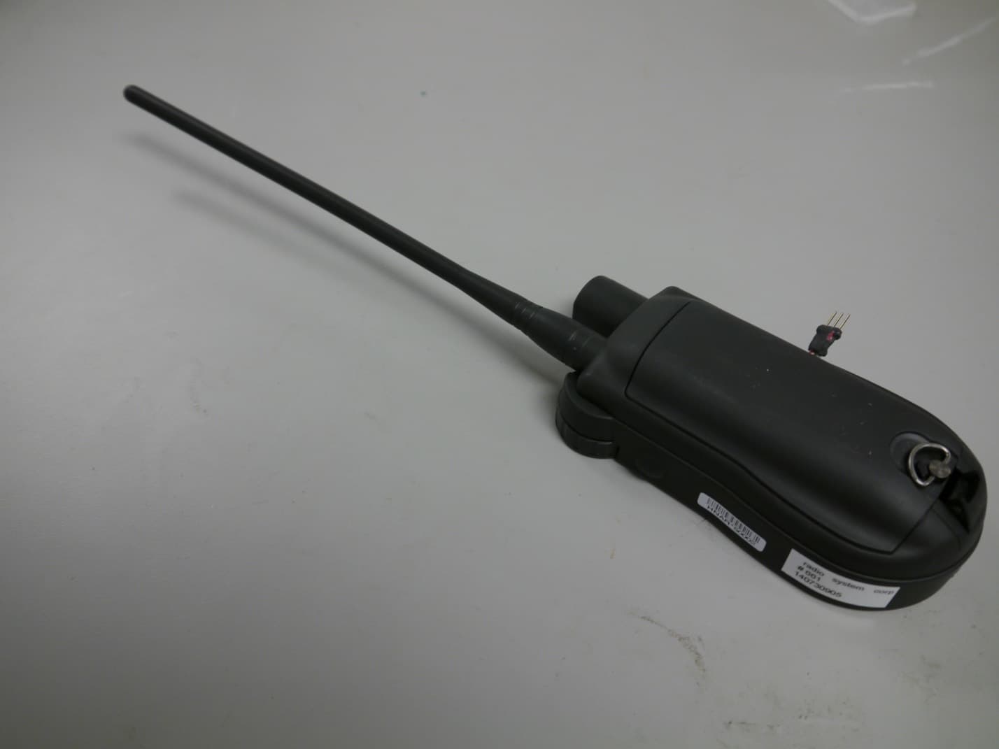
Click to zoom
Application Details
- Equipment Class
- DSS - Part 15 Spread Spectrum Transmitter
- Date of Grant
- May 18, 2015
- Application Purpose
- Original Equipment
- Date of Application
- May 04, 2015
- Equipment Note
- Wireless Dog Trainer
- Frequency Range
- 916.26250000 - 917.48750000
- Company
- Radio Systems Corp
- Country
- United States
Documents & Files
Document Text
Text extracted from the exhibit documents filed with the FCC. Open a document above to read the original.
Users Manual
OPERATING GUIDE PLEASE READ THIS ENTIRE GUIDE BEFORE BEGINNING 2SPORTDOG.COM IMPORTANT SAFETY INFORMATION EXPLANATION OF ATTENTION WORDS AND SYMBOLS USED IN THIS GUIDE This is the safety alert symbol. It is used to alert you to potential personal injury hazards. Obey all safety messages that follow this symbol to avoid possible injury or death. WARNING indicates a hazardous situation which, if not avoided, could result in death or serious injury. CAUTION, used without the safety alert symbol, indicates a hazardous situation which, if not avoided, could result in harm to your dog. NOTICE is used to address safe use practices not related to personal injury • Not for use with aggressive dogs. Do not use this product if your dog is aggressive, or if your dog is prone to aggressive behavior. Aggressive dogs can cause severe injury and even death to their owner and others. If you are unsure whether this product is appropriate for your dog, please consult your veterinarian or a certified trainer. • This device contains Lithium-Ion (Li-Ion) batteries; never incinerate, puncture, deform, short-circuit, or charge with an inappropriate charger. Fire, explosion, property damage, or bodily harm may occur if this warning is not followed. • Risk of explosion if battery is replaced by an incorrect type. Dispose of used batteries according to the regulations in your area. • Batteries should never be removed from the battery compartment for charging. • Do not charge the batteries in areas with high temperature (100°F +). • Keep batteries away from children. • Using your TEK™ Series Location and Training System while operating a motor vehicle can be distracting. Always pay full attention to operating your vehicle. • Always be alert to your surroundings when navigating to a way point. Do not cross dangerous terrain or obstacles as you move. Please read and follow the instructions in this manual. Proper fit of the collar is important. A collar worn for too long or made too tight on the dog’s neck may cause skin damage. This is called bed sores; it is also called decubitus ulcers or pressure necrosis. • Avoid leaving the collar on the dog for more than 12 hours per day. • When possible, reposition the collar on the dog’s neck every 1 to 2 hours. • Check the fit to prevent excessive pressure; follow the instructions in this manual. • Never connect a leash/lead to the Collar Receiver; it will cause excessive pressure on the contacts. • When using a separate collar for a leash/lead, don’t put pressure on the electronic collar. • Wash the dog’s neck area and the contacts of the collar weekly with a damp cloth. 3 SPORTDOG.COM • Examine the contact area daily for signs of a rash or a sore. • If a rash or sore is found, discontinue use of the collar until the skin has healed. • If the condition persists beyond 48 hours, see your veterinarian. For additional information on bed sores and pressure necrosis, please visit the Support section for remote trainers at www.sportdog.com. These steps will help keep your dog safe and comfortable. Millions of dogs are comfortable while they wear stainless steel contacts. Some dogs are sensitive to contact pressure. You may find after some time that your dog is very tolerant of the collar. If so, you may relax some of these precautions. It is important to continue daily checks of the contact area. If redness or sores are found, discontinue use until the skin has fully healed. • You may need to trim the hair in the area of the Contact Points or switch to the longer Contact Points to ensure consistent contact. Never shave the dog’s neck; this may lead to a rash or infection. • You should not make the collar any tighter than is required for good contact. A collar that is too tight will increase the risk of pressure necrosis in the contact area. • Unauthorized changes or modifications to the equipment may violate FCC regulations and could void the user’s authority to operate the equipment. • Taking product apart can cause damage and void your warranty. Contact the Customer Care Center for battery replacement service. THE DATA IN THIS SYSTEM HAS BEEN PROVIDED BY DELORME IN PARTNERSHIP WITH RADIO SYSTEMS® CORPORATION. IT IS SUITABLE AND INTENDED ONLY FOR GENERAL VISUAL REFERENCE USE. IT SHOULD NOT BE USED FOR ANY PURPOSE REQUIRING EXACT MEASUREMENT OF DISTANCE OR DIRECTION, OR FOR PRECISION IN ADDRESS LOCATION OR IN THE DEPICTION OF GEOGRAPHIC FEATURES. ROUTING DIRECTIONS SHOULD BE USED ONLY AS A TRAVEL AID AND MUST ALWAYS BE VISUALLY VERIFIED BY THE USER ON THE GROUND AND EXECUTED WITH DUE REGARD TO TRAFFIC AND ROAD CONDITIONS, ROAD SIGNS AND REGULATIONS. Please note that the Data is merely a graphical representation of geographic features appearing on the face of the earth. The Data may include features, such as roads, trails, etc., that are located on private property. Nothing in this License grants the use of, or is intended to imply the right to use, any such private property. You should respect all landowner restrictions. You are solely responsible for complying with all legal requirements relating to land use and for your own safety and for the consequences of your actions in your use of the Data. • Avoid using a high-powered radio (greater than 5 watts) in close proximity to the TEK™ Series Location and Training System. It may cause irreversible damage to the TEK Series Location and Training System. • Avoid chemical cleaners and solvents that can damage plastic components. • Do not store the TEK Series Location and Training System where prolonged exposure to temperature extremes may occur, because permanent damage may result. • When storing the device for an extended time, store within the following temperature range: from 32°F to 77°F (from 0° to 25°C). • Do not leave the device exposed to a heat source or in a high-temperature location, such as in the sun in an unattended vehicle. To prevent damage, remove the device from the vehicle or store it out of direct sunlight, such as…
Text truncated - open the document above for the full version.
Block Diagram
LCD DISPLAY PROCESSOR Master Crystal osc. 24MHz RTC Crystal osc. 32.768kHz MPU PLL: 1GHz Core PLL: 2GHz Display PLL: 200 DRR PLL: 400MHz L3F_CLK: 200MHz SPI_CLK: 48MHz MMC_CLK: 96MHz UART_CLK: 48MHz I2C_CLK: 48MHz MPU_CLK: 500MHz USB_PHY_CLK: 960MHz LpDRR_CLK: 200MHz POWER MANAGEMENT IC 3.7V LI-ion BATTERY WITH SAFETY CIRCUIT USB 2.0 CONNETOR LpDDR eMMC uSD-card EEPROM USER INTERFACE ON/OFF, Switces, Encoder, Vibration motor Ambient Light Sensor Audio Codec with Amplifier Internal RC_CKL 8.2MHz Bluetooth Module 2402—2480MHz 26MHz oscillator Rx/Tx RF OUT 902 — 928MHz TCXO 32MHz VCO 1.8GHz IF 468.75 kHz RF IN 902 — 928MHz SAW Filter 902-928MHz SAW Filter 902-928MHz Delicated PCB Antenna 2402—2480MHz PA LNA TX/RX SW Power Amplifier + Switch 902 — 928MHz Low pass filter LP < 1.1GHz Speaker TEK 2.0 HandHeld Unit Block Diagram GPS / GLONASS Module 1575—1608MHz TCXO 26MHz RTC 32.768kHz Delicated Helix Antenna 1575—1608MHz RF-section Delicated Whip Antenna 902—928MHz = RF– signal path = Control / data / Signal path
ID Label/Location Info
300-2791 Color: N/A Process: Laser Etch RSC Part #: 417-899 Description: ARTWORK MN&SN TEK 2.0 HNA ROHS Created by: CL Initial Creation Date: 6-30-2014 Approved by: JJAMESON Date Approved: 7-18-2014 Program used: ILLUSTRATOR CS6 Revision: 001 ECO: RSC10647 Revision Description: Updated model number Revision Date: 7-18-2014 XXXXXXXXXXXXX MOD: SDT52-14791 IC:2721A-3002791 FCC ID: KE3-3002791 5VDC 1000mA HNARRRNNNN Note: 1. Scale: 1:1 2. Dimension are in MM. 3. XXXXXXXXXXXXX: refer to 490-897 latest version, product serial number format section. 4. HNARRRNNNN: RRR = revision number of software. (The digits is unstable, this is for reference only.) NNNN = 4-digit sequential number starting at 0001.(The number will consist of number 0 thru 9 and alphabet letters from A thru F. Once the number gets to 0009 it will go to 000A, continuing to sequence thru the Alphabet.) Contains FCC ID: T7V1315
Internal Photos
GPS Receive Antenna Bluetooth Antenna 915 MHz Antenna Feed
Operational Description
P a g e | 1 TEK 2.0 HAND-HELD BASIC FUNCTIONAL DESCRIPTION The Hand-Held unit block diagram description Processor The processor type is AT3345 with AMR Cortex-A8 core. - Clock speed is 800MHz - Android operating system Main functions of the processor are next: - Make terrain map calculations, rotations and visualize maps via LCD display - User interface via rotary encoder and switches - Measure own navigation coordinates and speed via GPS / GLONASS module - Receive GPS-collar location messages via RF-receiver and visualize objects to the LCD display - Transmit stimulation commands to the GPS-collar via RF-transmitter - Transmit own geological location to another Hand Held units in same group via RF- transmitter - Power management controlling via power management IC - Battery recharge control via power management IC - Two way communication via Bluetooth module - Two way communication via USB 2.0 - Generate audio signals and sounds via audio codec IC - Measure ambient light level for adjust the LCD display back light level - Save / read data from the memories - Save / read user settings to / from the memory Memory - LPDDR1 memory with 200MHz bus for the RAM memory usage - eMMC memory for the map memory - uSD card memory for the user special maps and files - EEPROM for settings and calibration data User Interface - Rotary encoder for move cursor in menu - Switches for make selections and settings - Side switches for send stimulation commands to the GPS-collar unit ́s - Vibration module for the alarms and warnings RF-section - Si4463 Transceiver IC works from 866 to 915MHz band. Modulation GFSK, data speed 4800bit/s. Channel separation 25kHz. - SAW filters dedicated for each frequency band. Reduce spurious emissions and provide out-of-band interference rejection. P a g e | 2 - Power amplifier RF6569 (PA) for amplify Si4463 Tx RF signal from 10-20mW to 0.5W or 1W. The Tx/Rx RF-switch is integrated to the PA - Low pass filter is designed for reduce spurious emissions of the PA - Low Noise Amplifier (LNA) amplify received signal from the whip antenna GPS / GLONASS - Parallel GPS / GNSS receiver. 99 channels for search and 33 for tracking Bluetooth - The Bluetooth module with the integrated stack. - Class 1 or 2 Audio codec - Audio codec is for generate sounds and play the MP3 files. - Integrated 1W speaker amplifier Power Management IC (PMIC) - The PMIC regulate all used voltages for the Processor and accessories - Integrated linear re-charger for the Lithium-ion battery Ambient light Sensor - Sensor for the ambient light level measure from the environment. By using this information the processor will adjust the LCD display back light brightness via the PMIC USB - The USB 2.0 connector is for recharge the battery and communication interface to the another devices Li-ion Battery - 4400mAh Li-ion battery with the integrated safety circuit and the NTC resistor Antennas - All antennas are matched to the used frequency and impedance The TEK 2.0 866/915 Hand-Held unit has four different frequency band versions. 1. The FCC / IC version works in frequency band 902 – 916 MHz (FCC, CFR 47. §15.247 / IC, RSS-210, Annex 8) 28dBm, 50 Rx + 50 Tx (25 kHz) channel, frequency hopping. 2. The AU version works in frequency band 915 – 916 MHz (AS NZS 4268-2008) 28dBm, 20 Rx + 20 Tx (25 kHz) channel, frequency hopping. 3. The CE version works in frequency band 869,400 - 869,650 MHz (EN 300 220-1) 27dBm, 5 Rx + 5 Tx (25 kHz) channel, frequency hopping. 4. The NZ version works in frequency band 864,000 – 868,000MHz (EN 300 220-1) 28dBm, 20 Rx + 20 Tx (25 kHz) channel, frequency hopping. P a g e | 3 Hand-Held unit utilizes the frequency band as a communication link and also includes a GPS engine to acquire location coordinates and exact GPS time. The user is not able to configure the Hand-Held unit to different frequencies what are programmed in the Hand-Held unit frequency tables. Note: See sample frequency tables and end of this document. Each unit has user ID. The user can change or modify user ID. The user ID will match the GPS collars to the Hand-Held units. Synchronize of the used receiver frequency at the time will be done by checking GPS time. The Hand-Held and GPS-collar units will change frequency channel every 215ms (RX window). GPS- collar transmission time is around 142ms every 3rd second. GPS-collar transmission period will be change randomly a little every time for the Listen Before Talk. Nominal transmission period is around 3 second but transmission period will change randomly few +/- ms every time for avoid over lapping. The Hand-Held unit send own position information to another Hand-Held units every xx seconds by using same protocol. The hopped frequency channels are used to receive GPS coordinate data from the GPS-collar unit or the Hand-Held units. The GPS-collar and Hand-Held units synchronized to same frequency hopping algorithm by using the GPS time. That makes possible communication between the units at the time. If the user has the optional trainer module, E-collar module in the GPS-collar, the Hand-Held unit can be used as a transmitter by using hopping channels for remote control training purposes. Timing of training transmission hopping will based to the internal timers. Synchronize between the Hand-Held and E-collar units will happen from transmitted and received data frames. Received data frame will start up internal timer in the E-collar for time to change next used frequency. Tx timings for the Handheld unit (FCC & IC). Spectrum Access Techniques Minimum transmitter Off- time, (included LBT and Dead time) 32.5ms LBT Minimum Listening Time 5ms - 10ms Dead Time between LBT and Tx on time 2 - 3ms Maximum Transmitter On- 82.5ms P a g e | 4 time Transmit timeout Min 5.75s (50CH) Transmit timeout Max 11.5s (50CH * 2) Transmit logout min between stimulation commands 5s Tx timings for the Handheld unit (AU, CE & NZ). Spectrum Access Techniques Minimum transmitter Off-time (included LBT and De…
Text truncated - open the document above for the full version.
RF Exposure Info
Frequency, GHz Min Separation distance to Body mm Min Separation distance to Extremity mm Max Power + Tolerance dBm Antenna gain, dBi Calculated Max Power, mW EIPR 1g head / body 10g Extremity 0.91612.06.57.681.00 10 0.801.37 Stand Along SAR Test Exclusion According to KDB447498D01 General RF Exposure Guidance v05r02 SAR DOES NOT apply for head / body worn operating conditions SAR DOES NOT apply for extremety operating conditions Closest distance to body Closest distance to hand.
RF Exposure Info
Test Report Number:3543741EMC07 Rev: 2 Radio Systems / Sport Dog Tek 2.0 Page: 1 of 26 Remarks: This report details the results of the testing carried out on one sample, the results contained in this test report do not relate to other samples of the same product. The manufacturer should ensure that all products in series production are in conformity with the product sample detailed in this report. This report may only be reproduced and distributed in full. If the product in this report is used in any configuration other than that detailed in the report, the manufacturer must ensure the new system complies with all relevant standards. Any mention of SGS International Electrical Approvals or Testing done by SGS International Electrical Approvals in connection with distribution or use of the product described in this report must be approved by SGS international Electrical Approvals in writing. SAR TEST REPORT Project Number: 3543741 Report Number: 3543741EMC07 Revision Level: 2 Client: Radio Systems Equipment Under Test: GPS Handheld Unit Product Name: Sport DogTek 2.0 Handheld Unit Applicable Standards: IEEE STD 1528: 2013 EN 62209-2:2010 Report issued on: 18 May 2015 Test Result: Compliant Equipment Class Mode Band Frequency (MHz) Measured Conducted Power (dBm) SAR 1g Head W/kg 1g Body W/kg 10g Limb W/kg DSS/DTS Bluetooth US 2402 - 2480 10.1 NA 0.306 0.291 ISM FHSS US 916.2-917.4 10 eirp calc NA 0.1 est 0.07 est Simultaneous NA 0.406 0.298 Tested by: Fabian Nica, Senior Engineering Technician Reviewed by: David Schramm, EMC/RF/SAR/HAC Manager Test Report Number:3543741EMC07 Rev: 2 Radio Systems / Sport Dog Tek 2.0 Page: 2 of 26 SGS North America Inc. Consumer Testing Services 620 Old Peachtree Road NW, Suite 100, Suwanee, GA 30024 t (770) 570-1800 www.us.sgs.com/cts Member of the SGS Group (SGS SA) Table of Contents 1 GENERAL INFORMATION ............................................................................................................................................. 3 1.1 CLIENT INFORMATION ......................................................................................................................................................... 3 1.2 TEST LABORATORY ............................................................................................................................................................. 3 1.3 GENERAL INFORMATION OF EUT ....................................................................................................................................... 3 2 NOMINAL AND MAXIMUM POWER SPECIFICATIONS ............................................................................................. 5 3 TEST METHODOLOGY .................................................................................................................................................. 6 4 TEST EQUIPMENT .......................................................................................................................................................... 7 4.1 TEST SYSTEM BLOCK DIAGRAM ......................................................................................................................................... 8 5 LIQUID PARAMETERS CHECK .................................................................................................................................. 10 5.1 TISSUE VERIFICATION ....................................................................................................................................................... 10 6 SAR MEASUREMENT SYSTEM VERIFICATION ...................................................................................................... 11 6.1 PERFORMANCE CHECK MEASUREMENT CONDITIONS ....................................................................................................... 11 6.2 SYSTEM VERIFICATION ..................................................................................................................................................... 11 7 MEASUREMENT PROCEDURE .................................................................................................................................. 12 7.1 HEAD SAR CONFIGURATION ............................................................................................................................................ 13 7.1.1 SAM Specifications ................................................................................................................................................ 13 7.1.2 Handset Reference Points .................................................................................................................................... 13 7.1.3 Ear reference .......................................................................................................................................................... 14 7.1.4 Cheek positions ...................................................................................................................................................... 14 7.1.5 Tilt Position .............................................................................................................................................................. 15 8 CONDUCTED OUTPUT POWER VERIFICATION ..................................................................................................... 16 9 BLUETOOTH BODY SAR MEASUREMENT RESULTS ........................................................................................... 17 10 UNCERTAINTY BUDGET ......................................................................................................................................... 18 11 SAR PLOTS ................................................................................................................................................................ 19 12 SYSTEM CHECK PLOT ............................................................................................................................................ 21 13 SETU…
Text truncated - open the document above for the full version.
Schematics
Release to Production Hapi 001 001 06/17/2014 RSC10647 SCHM-600-627_R01 04/21/2014 04/21/2014 10427 Petsafe Way - Knoxville, TN 37932-3369 - (865)777-5404 THESE PURPOSES. BE DESTROYED OR RETURNED TO RSC WHEN NO LONGER REQUIRED FOR REQUIRING IT'S USE FOR RSC AUTHORIZED PURPOSES. THIS DOCUMENT SHALL SHALL NOT BE REPRODUCED NOR DISCLOSED TO ANYONE EXCEPT THOSE CORPORATION. THIS DRAWING AND THE INFORMATION CONTAINED HEREIN THIS DRAWING IS THE PROPERTY OF AND PROPRIETARY TO RADIO SYSTEMS 100-1193_R01 SCH_600-627 COMPANY CONFIDENTIAL Hapi Hapi C F E F E 1 A B C D 1 2 3 4 5 6 RADIO SYSTEMS CORPORATION D TEK 2.0 HANDHELD GPS REV: FILE NAME: SIZE: DATED: DRAWN: ENGINEER: C COPYRIGHT DATED: SHEET: 1 OF: 10 C B A 6 REVISION RECORD DESCRIPTION REV DATE BY 5 4 3 2 RSC NUMBER: BOARD NUMBER: SCHEMATIC TITLE: ECO/PRO 868MHZ / 915 MHZ HAND HELD TRANSCEIVER RSC 2012 TEK 2.0 HandHeld Unit PAGE NO. SCHEMATIC PAGE 1. 2. 3. 4. 5. 6. 7. 8. 9. 10. COVER PAGE PROCESSOR 1 OF 3 PROCESSOR 2 OF 3 PROCESSOR 3 OF 3 POWER MANAGEMENT LDC, USER INTERFACE AND SYSTEM BOOT LPDDR MEMORY AND SD MMC INTERFACE RF-TRANSCEIVER GPS, BLUETOOTH AND SENSORS AUDIO CODEC, USB, VIBM. AND JTAG REV. DESCRIPTION 001. Release to Production Release to Production Hapi 001 06/17/2014 RSC10647 04/21/2014 04/21/2014 100-1193_R01 001 SCHM-600-627_R01 10427 Petsafe Way - Knoxville, TN 37932-3369 - (865)777-5404 THESE PURPOSES. BE DESTROYED OR RETURNED TO RSC WHEN NO LONGER REQUIRED FOR REQUIRING IT'S USE FOR RSC AUTHORIZED PURPOSES. THIS DOCUMENT SHALL SHALL NOT BE REPRODUCED NOR DISCLOSED TO ANYONE EXCEPT THOSE CORPORATION. THIS DRAWING AND THE INFORMATION CONTAINED HEREIN THIS DRAWING IS THE PROPERTY OF AND PROPRIETARY TO RADIO SYSTEMS COMPANY CONFIDENTIAL 868MHZ / 915 MHZ HAND HELD TRANSCEIVER TEK 2.0 HANDHELD GPS C F E F E 1 A B C D 1 2 3 4 5 6 RADIO SYSTEMS CORPORATION D REV: FILE NAME: SIZE: DATED: DRAWN: Hapi ENGINEER: Hapi C COPYRIGHT DATED: SHEET: 2 OF: 10 C B A 6 REVISION RECORD DESCRIPTION REV DATE BY 5 4 3 2 RSC NUMBER: BOARD NUMBER: SCH_600-627 SCHEMATIC TITLE: ECO/PRO RSC 2012 BT_SHUTD 06/17/2014 HAP Production R01 RSC10647 [MMC0_DAT3/GPMC_A20/UART4_CTSN/TIMER5/UART1_DCDN/PR1_PRU0_PRU_R30_8/PR1_PRU0_PRU_R31_8/GPIO2_26] [MMC0_DAT2/GPMC_A21/UART4_RTSN/TIMER6/UART1_DSRN/PR1_PRU0_PRU_R30_9/PR1_PRU0_PRU_R31_9/GPIO2_27] [MMC0_DAT1/GPMC_A22/UART5_CTSN/UART3_RXD/UART1_DTRN/PR1_PRU0_PRU_R30_10/PR1_PRU0_PRU_R31_10/GPIO2_28] [MMC0_DAT0/GPMC_A23/UART5_RTSN/UART3_TXD/UART1_RIN/PR1_PRU0_PRU_R30_11/PR1_PRU0_PRU_R31_11/GPIO2_29] [MMC0_CMD/GPMC_A25/UART3_RTSN/UART2_TXD/DCAN1_RX/PR1_PRU0_PRU_R30_13/PR1_PRU0_PRU_R31_13/GPIO2_31] [MMC0_CLK/GPMC_A24/UART3_CTSN/UART2_RXD/DCAN1_TX/PR1_PRU0_PRU_R30_12/PR1_PRU0_PRU_R31_12/GPIO2_30] [GPMC_A11/GMII2_RXD0/RGMII2_RD0/RMII2_RXD0/GPMC_A27/PR1_MII1_RXER/MCASP0_AXR1/GPIO1_27] [GPMC_A10/GMII2_RXD1/RGMII2_RD1/RMII2_RXD1/GPMC_A26/PR1_MII1_RXDV/MCASP0_AXR0/GPIO1_26] [GPMC_A9/GMII2_RXD2/RGMII2_RD2/MMC2_DAT7/GPMC_A25/PR1_MII_MR1_CLK/MCASP0_FSX/GPIO1_25] [GPMC_A8/GMII2_RXD3/RGMII2_RD3/MMC2_DAT6/GPMC_A24/PR1_MII1_RXD0/MCASP0_ACLKX/GPIO1_24] [GPMC_A7/GMII2_RXCLK/RGMII2_RCLK/MMC2_DAT5/GPMC_A23/PR1_MII1_RXD1/EQEP1_STROBE/GPIO1_23] [GPMC_A6/GMII2_TXCLK/RGMII2_TCLK/MMC2_DAT4/GPMC_A22/PR1_MII1_RXD2/EQEP1_INDEX/GPIO1_22] [GPMC_A5/GMII2_TXD0/RGMII2_TD0/RMII2_TXD0/GPMC_A21/PR1_MII1_RXD3/EQEP1B_IN/GPIO1_21] [GPMC_A4/GMII2_TXD1/RGMII2_TD1/RMII2_TXD1/GPMC_A20/PR1_MII1_TXD0/EQEP1A_IN/GPIO1_20] [GPMC_A3/GMII2_TXD2/RGMII2_TD2/MMC2_DAT2/GPMC_A19/PR1_MII1_TXD1/EHRPWM1B/GPIO1_19] [GPMC_A2/GMII2_TXD3/RGMII2_TD3/MMC2_DAT1/GPMC_A18/PR1_MII1_TXD2/EHRPWM1A/GPIO1_18] [GPMC_A1/GMII2_RXDV/RGMII2_RCTL/MMC2_DAT0/GPMC_A17/PR1_MII1_TXD3/EHRPWM0_SYNCO/GPIO1_17] [GPMC_A0/GMII2_TXEN/RGMII2_TCTL/RMII2_TXEN/GPMC_A16/PR1_MII_MT1_CLK/EHRPWM1_TRIPZONE_INPUT/GPIO1_16] [GPMC_AD15/LCD_DATA16/MMC1_DAT7/MMC2_DAT3/EQEP2_STROBE/PR1_ECAP0_ECAP_CAPIN_APWM_O/PR1_PRU0_PRU_R31_15/GPIO1_15] [GPMC_AD14/LCD_DATA17/MMC1_DAT6/MMC2_DAT2/EQEP2_INDEX/PR1_MII0_TXD0/PR1_PRU0_PRU_R31_14/GPIO1_14] [GPMC_AD13/LCD_DATA18/MMC1_DAT5/MMC2_DAT1/EQEP2B_IN/PR1_MII0_TXD1/PR1_PRU0_PRU_R30_15/GPIO1_13] [GPMC_AD12/LCD_DATA19/MMC1_DAT4/MMC2_DAT0/EQEP2A_IN/PR1_MII0_TXD2/PR1_PRU0_PRU_R30_14/GPIO1_12] [GPMC_AD11/LCD_DATA20/MMC1_DAT3/MMC2_DAT7/EHRPWM2_SYNCO/PR1_MII0_TXD3//GPIO0_27] [GPMC_AD10/LCD_DATA21/MMC1_DAT2/MMC2_DAT6/EHRPWM2_TRIPZONE_INPUT/PR1_MII0_TXEN//GPIO0_26] [GPMC_AD9/LCD_DATA22/MMC1_DAT1/MMC2_DAT5/EHRPWM2B/PR1_MII0_COL//GPIO0_23] [GPMC_AD8/LCD_DATA23/MMC1_DAT0/MMC2_DAT4/EHRPWM2A/PR1_MII_MT0_CLK//GPIO0_22] [GPMC_AD7/MMC1_DAT7//////GPIO1_7] [GPMC_AD6/MMC1_DAT6//////GPIO1_6] [GPMC_AD5/MMC1_DAT5//////GPIO1_5] [GPMC_AD4/MMC1_DAT4//////GPIO1_4] [GPMC_AD3/MMC1_DAT3//////GPIO1_3] [GPMC_AD2/MMC1_DAT2//////GPIO1_2] [GPMC_AD1/MMC1_DAT1//////GPIO1_1] [GPMC_AD0/MMC1_DAT0//////GPIO1_0] [GPMC_WPN/GMII2_RXERR/GPMC_CSN5/RMII2_RXERR/MMC2_SDCD/PR1_MII1_TXEN/UART4_TXD/GPIO0_31] [GPMC_WAIT0/GMII2_CRS/GPMC_CSN4/RMII2_CRS_DV/MMC1_SDCD/PR1_MII1_COL/UART4_RXD/GPIO0_30] [GPMC_BE1N/GMII2_COL/GPMC_CSN6/MMC2_DAT3/GPMC_DIR/PR1_MII1_RXLINK/MCASP0_ACLKR/GPIO1_28] [GPMC_BE0N_CLE//TIMER5/////GPIO2_5] [GPMC_ADVN_ALE//TIMER4/////GPIO2_2] [GPMC_OEN_REN//TIMER6/////GPIO2_3] [GPMC_WEN//TIMER6/////GPIO2_4] [GPMC_CSN3///MMC2_CMD/PR1_MII0_CRS/PR1_MDIO_DATA/EMU4/GPIO2_0] [GPMC_CSN2/GPMC_BE1N/MMC1_CMD/PR1_EDIO_DATA_IN7/PR1_EDIO_DATA_OUT7/PR1_PRU1_PRU_R30_13/PR1_PRU1_PRU_R31_13/GPIO1_31] [GPMC_CSN1/GPMC_CLK/MMC1_CLK/PR1_EDIO_DATA_IN6/PR1_EDIO_DATA_OUT6/PR1_PRU1_PRU_R30_12/PR1_PRU1_PRU_R31_12/GPIO1_30] [GPMC_CSN0///////GPIO1_29] [GPMC_CLK/LCD_MEMORY_CLK/GPMC_WAIT1/MMC2_CLK/PR1_MII1_CRS/PR1_MDIO_MDCLK/MCASP0_FSR/GPIO2_1] [NTRST] [XDMA_EVENT_INTR1//TCLKIN/CLKOUT2/TIMER7/PR1_PRU0_PRU_R31_16/EMU3/GPIO0_20] [XDMA_EVENT_INTR0//TIMER4/CLKOUT1/SPI1_CS1/PR1_PRU1_PRU_R31_16/EMU2/GPIO0_19] [NNMI] [RTC_PORZ] [NRESETIN_OUT] [PORZ] [DDR_RESETN] [DDR_DQSN1] [DDR_DQSN0] [DDR_WEN] [DDR_RASN] [DDR_CASN] [DDR_CSN0] [DDR_CKN] [OSC1_OUT] [OSC1_IN] [OSC0_OUT] [OSC0_IN] AM335x ZCZ Package A6 RTC_XTALIN A4 RTC_XTALOUT V10 XTALIN U11 XTALOUT V12 GPMC_CLK V6 …
Text truncated - open the document above for the full version.
Test Report
Test Report Number: 3543741EMC02 Rev: 0 Radio Systems / Sport Dog Tek 2.0 Page: 1 of 32 SGS North America Inc. Consumer Testing Services 620 Old Peachtree Road NW, Suite 100, Suwanee, GA 30024 t (770) 570-1800 www.us.sgs.com/cts Member of the SGS Group (SGS SA) EMC Test Report Project Number: 3543741EMC01 Report Number: 3543741EMC01 Revision Level: 0 Client: Radio Systems Equipment Under Test: Sport DogTek 2.0 Handheld Unit Applicable Standards: ANSI C63.10: 2009 FCC Part 15 Subpart C, § 15.247 RSS-210, Issue 8, December 2010 Report issued on: 28AUG2014 Test Result: Compliant Tested by: Brian Forster, EMC Engineer Reviewed by: David Schramm, EMC Manager Test Report Number: 3543741EMC02 Rev: 0 Radio Systems / Sport Dog Tek 2.0 Page: 2 of 32 SGS North America Inc. Consumer Testing Services 620 Old Peachtree Road NW, Suite 100, Suwanee, GA 30024 t (770) 570-1800 www.us.sgs.com/cts Member of the SGS Group (SGS SA) Table of Contents 1 SUMMARY OF TEST RESULTS ..................................................................................................................................... 4 1.1 MODIFICATIONS REQUIRED FOR COMPLIANCE .............................................................................................................. 4 2 GENERAL INFORMATION ............................................................................................................................................. 5 2.1 CLIENT INFORMATION ................................................................................................................................................... 5 2.2 TEST LABORATORY ....................................................................................................................................................... 5 2.3 GENERAL INFORMATION OF EUT .................................................................................................................................. 5 2.4 OPERATING MODES AND CONDITIONS .......................................................................................................................... 5 3 OCCUPIED BANDWIDTH ............................................................................................................................................... 6 3.1 TEST RESULT ................................................................................................................................................................. 6 3.2 TEST METHOD ............................................................................................................................................................... 6 3.3 TEST SITE ...................................................................................................................................................................... 6 3.4 TEST EQUIPMENT .......................................................................................................................................................... 6 3.5 TEST DATA .................................................................................................................................................................... 7 4 PEAK OUTPUT POWER .................................................................................................................................................. 8 4.1 TEST RESULT ................................................................................................................................................................. 8 4.2 TEST METHOD ...........…
Text truncated - open the document above for the full version.
Contact Information
Applicant
Deborah J. LeMaster(Regulatory Compliance Specialist)
Technical Contact
Radio Systems CorporationCindy Allen
[email protected]8658245431
10427 Petsafe Way · Knoxville · United States
Test Firm
SGS North America, Inc.David Schramm
Technical Specifications
| # | Rule Parts | Frequency Range | Power Output |
|---|---|---|---|
| 1 | 15C | 916.2625 MHz - 917.4875 MHz | 345.00 mW |
Other Applications from Radio Systems Corp

KE3-PIF150-2
Jun 18, 2026Stay & Play Wireless Fence
Equipment Class
DCD - Part 15 Low Power Transmitter Below 1705 kHz
KE3-3003841
Jun 05, 2026PetSafe HydroSphere 60 oz Cordless Fountain
Equipment Class
FDS - Part 15 Field Disturbance Sensor
KE3-3003832
Apr 08, 2026GPS Tracker Collar
Equipment Class
DTS - Digital Transmission System
KE3-3003791
Jul 01, 2024MURS radio device
Equipment Class
TNB - Licensed Non-Broadcast Station Transmitter
KE3-3003803
Apr 06, 2024Dog Training Collar
Equipment Class
DSC - Part 15 Security/Remote Control Transmitter