KE3-3003057Low power transmitter
Radio Systems Corp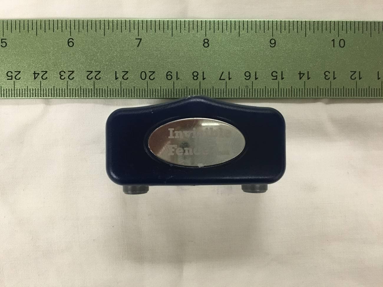
Click to zoom
Application Details
- Equipment Class
- DXX - Part 15 Low Power Communication Device Transmitter
- Date of Grant
- Dec 02, 2015
- Application Purpose
- Original Equipment
- Date of Application
- Dec 02, 2015
- Equipment Note
- Low power transmitter
- Frequency Range
- 433.92000000 - 433.92000000
- Company
- Radio Systems Corp
- Country
- United States
Documents & Files
Document Text
Text extracted from the exhibit documents filed with the FCC. Open a document above to read the original.
Users Manual
Boundary Plus ® R23 & MicroLite ® Plus Computer Collar ® Units Owner’s Manual www.InvisibleFence.com 2 www.InvisibleFence.com Important Precautions •Invisible Fence ® Brand pet containment systems have contained over two million pets. However, there are some precautions you should take. • Read and retain manuals: Read the entire Owner’s Manual before using your new Invisible Fence ® Brand pet containment system. •Adhere to all warnings and cautions contained in any Invisible Fence ® Brand manual. WARNING indicates a hazardous situation, which, if not avoided, could result in death or serious injury. CAUTION used without the safety alert symbol, indicates a hazardous situation, which, if not avoided, could result in harm to your pet. NOTICE is used to address safe use practices not related to personal injury. • Never open a Power Cap ® Battery, dispose of it in a fire, recharge it, expose it to heat above 212º F (100º C), or expose its contents to water. Doing so can cause leakage or explosion and may lead to personal injury. • Not every pet can be trained to avoid the established boundary. Sometimes even a properly trained pet may cross the boundary. Therefore, Invisible Fence, Inc., as well as Invisible Fence ® Distributors and Dealers, cannot guarantee the system will, in all cases, keep a customer’s pet within the established boundary. Accordingly, if a customer has reason to believe that their pet may pose a danger to others, or harm itself, the customer should not rely solely upon the Invisible Fence ® Brand pet containment system to keep the pet from crossing the boundary. • Do not install, connect, or remove your system during a lightning storm. If the storm is close enough for you to hear thunder, it is close enough to create hazardous surges. Read and follow the important instructions on how to avoid pressure necrosis. Proper fit of the Computer Collar ® Unit is important. A Computer Collar ® Unit worn for too long or made too tight on the pet’s neck may cause skin damage. Ranging from redness to pressure ulcers; this condition is commonly known as bedsores. The following tips will help keep your pet safe and comfortable. Millions of pets are comfortable while they wear stainless steel posts. Some pets are sensitive to contact pressure. You may find after some time that your pet is very tolerant of the Computer Collar ® Unit. If so, you may relax some of these precautions. It is important to continue daily checks of the contact area. If redness or sores are found, discontinue use until the skin has fully healed. • Avoid leaving the Computer Collar ® Unit on the pet for more than 12 hours per day. • When possible, reposition the Computer Collar ® Unit on the pet’s neck every 1 to 2 hours. • Check the fit to prevent excessive pressure; follow the instructions in this manual. • Never connect a leash to the Computer Collar ® Unit; it will cause excessive pressure on the contacts. • When using a separate collar for a leash, don’t put pressure on the Computer Collar ® Unit. • Wash the pet’s neck area and the contacts of the Computer Collar ® Unit weekly with a damp cloth. • Examine the contact area daily for signs of a rash or a sore. • If a rash or sore is found, discontinue use of the Computer Collar ® Unit until the skin is healed. • If the condition persists beyond 48 hours, see your veterinarian. You may need to trim the hair in the area of the Correction Posts or switch to the longer Correction Posts to ensure consistent contact. Never shave the pet’s neck; this may lead to a rash or infection. WARNING CAUTION NOTICE WARNING CAUTION www.InvisibleFence.com3 To prevent an unintended correction: • The Computer Collar ® Unit should not be on your pet when the system is tested. • Remove the Computer Collar ® Unit before making any changes to your system. • Before placing the Computer Collar ® Unit on your pet, test the Boundary Area and Width after any change. • The use of any power source other than a Power Cap ® Battery may cause a Computer Collar ® Unit to operate erratically or fail. The use of unnecessary force may damage the case and render the Power Cap ® Battery inoperable. • Train your pet according to the instructions in the Invisible Fence ® Brand training manuals. Complete all steps before allowing your pet to run free. Do not become overly confident if your pet has become conditioned to the Invisible Fence ® Brand pet containment system sooner than expected. • Your Invisible Fence ® Brand Dealer has professionally installed your pet containment system and ensured it is working properly. You will want to perform periodic maintenance checks to make sure the system is properly functioning for your pet’s safe containment. • Check the Invisible Fence ® Brand transmitter periodically to make sure it is operating properly. To do this, simply bring the Computer Collar ® Unit to the edge of the containment field to verify function. • The transmitter has visual and audible signals to warn of a system malfunction. The transmitter should be installed where such signals may be easily seen and heard. If the transmitter is installed by the customer in an enclosed box, or in a place not readily accessible to the customer, the customer will not benefit from the system’s warning functions, for which Invisible Fence, Inc., as well as Invisible Fence ® Distributors and Dealers, assume no responsibility. • Do not attempt to service any Invisible Fence ® Brand equipment. Refer all service to your authorized Invisible Fence ® Brand Dealer. Only your authorized Invisible Fence ® Brand Dealer should make adjustments to your pet containment system. • All Invisible Fence ® Brand pet containment systems are designed for domesticated animal use only. Never attempt to use this product for any purpose not specifically described in this manual. • Use care when mowing, aerating, or trimming your lawn so as not to cut the loop wire. • If you have any questions about any aspect of your Invisible Fence ® B…
Text truncated - open the document above for the full version.
Cover Letter(s)
10427 PetSafe Way Knoxville, TN. 37932 865-777-5404 www.petsafe.net AGENCY AGREEMENT Federal Communications Commission Date: 9/18/2012 P.O. Box 429 Columbia, MD 21045 Gentlemen: By signature below, we hereby appoint US Tech employees Sandi McEnery, Alan Ghasiani and George Yang to act as our agents with regard to all FCC equipment authorizations. This appointment will remain in effect until otherwise notified. I further certify by signature below that no party (per 47 CFR 1.2002(b)) to the application is subject to a denial of Federal benefits, including FCC benefits, pursuant to Section 5301 of the Anti-Drug Abuse Act of 1988, 21 U.S.C. 853(a). This appointment includes the authority to complete FCC Form 731 on our behalf and sign the application as an authorized agent. Signature: ________________________ Name: Cindy Allen Title: Product Safety and Regulatory Specialist Date: 9/18/2012
Cover Letter(s)
Request for Confidentiality Date: ___November 20, 2015____ Subject: Confidentiality Request for: ___FCC ID: KE3-3003057 IC: 2721A-3003057 Pursuant to FCC 47 CRF 0.457(d) and 0.459 and IC RSP-100, Section 6, the applicant requests that a part of the subject FCC application be held confidential. Type of Confidentiality Requested Exhibit Short Term Permanent Block Diagrams Short Term External Photos Short Term Permanent Internal Photos Short Term Permanent Operation Description/Theory of Operation Short Term Permanent Parts List & Placement/BOM Short Term Permanent Tune-Up Procedure Short Term Permanent Schematics Short Term Test Setup Photos Short Term Permanent* User’s Manual Radio Systems has spent substantial effort in developing this product and it is one of the first of its kind in industry. Having the subject information easily available to "competition" would negate the advantage they have achieved by developing this product. Not protecting the details of the design will result in financial hardship. Permanent Confidentiality: The applicant requests the exhibits listed above as permanently confidential be permanently withheld from public review due to materials that contain trade secrets and proprietary information not customarily released to the public. NOTE for Industry Canada Applications: The applicant understands that until such time that IC distinguishes between Short Term and Permanent Confidentiality, either type of marked exhibit above will simply be marked Confidential when submitted to IC. Sincerely, By:__________________________ ___Sandi McEnery__- Agent (Signature/Title) (Print name)
External Photos
US Tech Test Report: FCC Part 15 Certification/ RSS 210 FCC ID: KE3-3003057 IC: 2721A-3003057 Test Report Number: 15-0262 Issue Date: November 19, 2015 Customer: Radio Systems Model: RIG00-15265 Page 1 of 7 EXTERNAL PHOTOGRAPHS Figure 1. Top View US Tech Test Report: FCC Part 15 Certification/ RSS 210 FCC ID: KE3-3003057 IC: 2721A-3003057 Test Report Number: 15-0262 Issue Date: November 19, 2015 Customer: Radio Systems Model: RIG00-15265 Page 2 of 7 Figure 2. Bottom View US Tech Test Report: FCC Part 15 Certification/ RSS 210 FCC ID: KE3-3003057 IC: 2721A-3003057 Test Report Number: 15-0262 Issue Date: November 19, 2015 Customer: Radio Systems Model: RIG00-15265 Page 3 of 7 Figure 3. Side 1 US Tech Test Report: FCC Part 15 Certification/ RSS 210 FCC ID: KE3-3003057 IC: 2721A-3003057 Test Report Number: 15-0262 Issue Date: November 19, 2015 Customer: Radio Systems Model: RIG00-15265 Page 4 of 7 Figure 4. Side 2 US Tech Test Report: FCC Part 15 Certification/ RSS 210 FCC ID: KE3-3003057 IC: 2721A-3003057 Test Report Number: 15-0262 Issue Date: November 19, 2015 Customer: Radio Systems Model: RIG00-15265 Page 5 of 7 Figure 5. Side 3 US Tech Test Report: FCC Part 15 Certification/ RSS 210 FCC ID: KE3-3003057 IC: 2721A-3003057 Test Report Number: 15-0262 Issue Date: November 19, 2015 Customer: Radio Systems Model: RIG00-15265 Page 6 of 7 Figure 6. Battery Pack Removed US Tech Test Report: FCC Part 15 Certification/ RSS 210 FCC ID: KE3-3003057 IC: 2721A-3003057 Test Report Number: 15-0262 Issue Date: November 19, 2015 Customer: Radio Systems Model: RIG00-15265 Page 7 of 7 Figure 7. Battery Pack
ID Label/Location Info
US Tech Test Report: FCC Part 15 Certification/ RSS 210 FCC ID: KE3-3003057 IC: 2721A-3003057 Test Report Number: 15-0262 Issue Date: November 20, 2015 Customer: Radio Systems Model: RIG00-15265 Page 1 of 2 SAMPLE LABEL LOCATION .63" 1.14" XXXXXXXXXXXXX BAR CODE PRINTS HERE MOD: RIG00-15265 REV: XXX BOUNDARY PLUS GEN2 RECEIVER Material: PET Color: White Printing: Black Process: Inkjet Printed Coating: Anti-friction RSC Part #: 402-15635 Description: LABEL UNIT SERIAL BARCODE RIG00-15265 Created by: Kendy Lai Initial Creation Date: DEC.18.2014 Approved by: Kevin Tolliver Date Approved: Program used: ILLUSTRATOR CS6 Revision: 000ECO: RSC11368 Revision Description: RELEASE TO PRODUCTION Revision Date: N/A DEC.22.2014 ® VENDOR TO ADD (IF APPLICABLE) 1. SERIALIZED BARCODE. 2. VENDOR CODE BEFORE LABEL PN. 3. REV: XXX (XXX IS THE SKU# REVISION, IT SHOULD CHANGE EVERY TIME WHEN SKU BE ECO’D) NOTE: 1. SERIALIZED BARCODE DEFINED BY U000019. 2. BARCODE FORMAT IS CODE 128. 3. CE MARK AS PROVIDED BY THE EUROPEAN COMMISION. A MIMIMUM HEIGHT OF 5mm IS REQUIRED. CE MARK CONFORMITY MARKING SHALL BE IN ACCORDANCE WITH COUNCIL DECISION 93/465/EC. 3. MUST MEET ALL REQUIREMENTS OF RoHS DIRECTIVE 2002/95/EC AS AMENDED 4. SCALE: 1 TO 1. 5. FILLER CURVE: R=2MM (X4) US Patents: 7046152, 7068174 , 7117822 7779788, 8047161, NZ578437 AU S2008205534, CAN2675582 IC : 2721A-3003057 FCC ID : KE3-3003057
Internal Photos
US Tech Test Report: FCC Part 15 Certification/ RSS 210 FCC ID: KE3-3003057 IC: 2721A-3003057 Test Report Number: 15-0262 Issue Date: November 19, 2015 Customer: Radio Systems Model: RIG00-15265 Page 1 of 3 INTERNAL PHOTOGRAPHS Figure 1. Solder Side of PCB US Tech Test Report: FCC Part 15 Certification/ RSS 210 FCC ID: KE3-3003057 IC: 2721A-3003057 Test Report Number: 15-0262 Issue Date: November 19, 2015 Customer: Radio Systems Model: RIG00-15265 Page 2 of 3 Figure 2. Component Side of PCB US Tech Test Report: FCC Part 15 Certification/ RSS 210 FCC ID: KE3-3003057 IC: 2721A-3003057 Test Report Number: 15-0262 Issue Date: November 19, 2015 Customer: Radio Systems Model: RIG00-15265 Page 3 of 3 Figure 3. Component Side of PCB Removed from Enclosure
Test Report
Page 1 of 24 Application For Title 47 USC Part 2, Subpart J, Paragraph 2.907 Equipment Authorization of Certification for an Intentional Radiator per Part 15, Subpart C, Paragraphs 15.207 and 15.209 And Industry Canada, Radio Standards Specifications: RSS Gen Issue 4 and RSS-210 Issue 8 For the Radio Systems Model: RIG00-15265 FCC ID: KE3-3003057 IC: 2721A-3003057 UST Project: 15-0262 Issue Date: November 19, 2015 Total Pages in This Report: 24 3505 Francis Circle Alpharetta, GA 30004 PH: 770-740-0717 Fax: 770-740-1508 www.ustech-lab.com Page 2 of 24 I certify that I am authorized to sign for the Test Agency and that all of the statements in this report and in the Exhibits attached hereto are true and correct to the best of my knowledge and belief: US TECH (Agent Responsible For Test): By: Alan Ghasiani Name: Title: Compliance Engineer – President Date November 19, 2015 This report shall not be reproduced except in full. This report may be copied in part only with the prior written approval of US Tech. The results contained in this report are subject to the adequacy and representative character of the sample provided. This report must not be used to claim product certification, approval, or endorsement by NVLAP, NIST or any agency of the Federal Government. 3505 Francis Circle Alpharetta, GA 30004 PH: 770-740-0717 Fax: 770-740-1508 www.ustech-lab.com US Tech Test Report: FCC Part 15 Certification/ RSS 210 FCC ID: KE3-3003057 IC: 2721A-3003057 Test Report Number: 15-0262 Issue Date: November 19, 2015 Customer: Radio Systems Model: RIG00-15265 Page 3 of 24 MEASUREMENT TECHNICAL REPORT COMPANY NAME: Radio Systems MODEL: RIG00-15265 FCC ID: KE3-3003057 IC: 2721A-3003057 DATE: November 19, 2015 This report concerns (check one): Original grant X Class II change Equipment type: 433.92 MHz Transmitter Deferred grant requested per 47 CFR 0.457(d)(1)(ii)? yes_____ No X If yes, defer until: ______N/A___________ date agrees to notify the Commission by N/A date of the intended date of announcement of the product so that the grant can be issued on that date. Report prepared by: US Tech 3505 Francis Circle Alpharetta, GA 30004 Phone Number: (770) 740-0717 Fax Number: (770) 740-1508 US Tech Test Report: FCC Part 15 Certification/ RSS 210 FCC ID: KE3-3003057 IC: 2721A-3003057 Test Report Number: 15-0262 Issue Date: November 19, 2015 Customer: Radio Systems Model: RIG00-15265 Page 4 of 24 Table of Contents Paragraph Title Page 1 General Information .......................................................................................... 6 1.1 Purpose of this Report .................................................................................. 6 1.2 Characterization of Test Sample ................................................................... 6 1.3 Product Description ...................................................................................... 6 1.4 Configuration of Tested System .................................................................... 6 1.5 Test Facility ................................................................................................... 7 2 Tests and Measurements ................................................................................. 9 2.1 Test Equipment ............................................................................................. 9 2.2 Modifications to EUT Hardware .................................................................. 10 2.3 Number of Measurements for Intentional Radiators (15.31(m)) .................. 10 2.4 Frequency Range of Radiated Measurements (Part 15.33)........................ 10 2.4.1 Intentional Radiator ................................................................................. 10 2.4.2 Unintentional Radiator ............................................................................ 11 2.5 Measurement Detector Function and Bandwidth (CFR 15.35) ................... 11 2.5.1 Detector Function and Associated Bandwidth ........................................ 11 2.5.2 Corresponding Peak and Average Requirements ................................... 11 2.5.3 Pulsed Transmitter Averaging ................................................................. 11 2.5.4 Transmitter Duty Cycle (47 CFR 15.35 (c)) .............................................. 12 2.6 EUT Antenna Requirements (CFR 15.203) ................................................ 13 2.7 Restricted Bands of Operation (Part 15.205) .............................................. 14 2.8 Intentional Radiator, Power Line Conducted Emissions (CFR 15.207) ....... 14 2.9 Intentional Radiator, Radiated Emissions (CFR 15.209, (IC RSS 210)) ..... 14 2.10 99% Occupied Bandwidth (IC RSS 210, A8.1) ........................................... 18 2.11 Unintentional/Intentional Radiator, Power line Emissions (CFR 15.107 and 15.207) ................................................................................................................. 20 2.12 Spurious Radiated Emissions (CFR 15.109) .............................................. 21 2.13 Measurement Uncertainty .......................................................................... 24 2.13.1 Conducted Emissions Measurement Uncertainty ................................. 24 2.13.2 Radiated Emissions Measurement Uncertainty .................................... 24 US Tech Test Report: FCC Part 15 Certification/ RSS 210 FCC ID: KE3-3003057 IC: 2721A-3003057 Test Report Number: 15-0262 Issue Date: November 19, 2015 Customer: Radio Systems Model: RIG00-15265 Page 5 of 24 List of Figures Figures Title Page Figure 1. Duty Cycle ................................................................................................ 12 Figure 2. Block Diagram of Test Configuration ........................................................ 13 Figure 3. 20 dB & 99% Bandwidth ........................................................................... 19 List of Tables Table Title Page Table 1. EUT and Peripherals ..............…
Text truncated - open the document above for the full version.
Test Setup Photos
US Tech Test Report: FCC Part 15 Certification/ RSS 210 FCC ID: KE3-3003057 IC: 2721A-3003057 Test Report Number: 15-0262 Issue Date: November 19, 2015 Customer: Radio Systems Model: RIG00-15265 Page 1 of 6 TEST CONFIGURATION PHOTOGRAPHS Figure 1. Radiated Emissions Test Setup US Tech Test Report: FCC Part 15 Certification/ RSS 210 FCC ID: KE3-3003057 IC: 2721A-3003057 Test Report Number: 15-0262 Issue Date: November 19, 2015 Customer: Radio Systems Model: RIG00-15265 Page 2 of 6 Figure 2. Radiated Emissions Test Setup (Below 30 MHz) US Tech Test Report: FCC Part 15 Certification/ RSS 210 FCC ID: KE3-3003057 IC: 2721A-3003057 Test Report Number: 15-0262 Issue Date: November 19, 2015 Customer: Radio Systems Model: RIG00-15265 Page 3 of 6 Figure 3. Radiated Emissions Test Setup (30 - 200 MHz) US Tech Test Report: FCC Part 15 Certification/ RSS 210 FCC ID: KE3-3003057 IC: 2721A-3003057 Test Report Number: 15-0262 Issue Date: November 19, 2015 Customer: Radio Systems Model: RIG00-15265 Page 4 of 6 Figure 4. Radiated Emissions Test Setup (200 Mhz - 1 GHz) US Tech Test Report: FCC Part 15 Certification/ RSS 210 FCC ID: KE3-3003057 IC: 2721A-3003057 Test Report Number: 15-0262 Issue Date: November 19, 2015 Customer: Radio Systems Model: RIG00-15265 Page 5 of 6 Figure 5. Radiated Emissions Test Setup (Above 1 GHz, Front View) US Tech Test Report: FCC Part 15 Certification/ RSS 210 FCC ID: KE3-3003057 IC: 2721A-3003057 Test Report Number: 15-0262 Issue Date: November 19, 2015 Customer: Radio Systems Model: RIG00-15265 Page 6 of 6 Figure 5. Radiated Emissions Test Setup (Above 1 GHz, Back View)
Contact Information
Applicant
Deborah J. LeMaster(Regulatory Compliance Specialist)
Test Firm
US TechGeorge Yang
Technical Specifications
| # | Rule Parts | Frequency Range | Power Output |
|---|---|---|---|
| 1 | 15C | 433.92 MHz - 433.92 MHz | - |
Other Applications from Radio Systems Corp

KE3-PIF150-2
Jun 18, 2026Stay & Play Wireless Fence
Equipment Class
DCD - Part 15 Low Power Transmitter Below 1705 kHz
KE3-3003841
Jun 05, 2026PetSafe HydroSphere 60 oz Cordless Fountain
Equipment Class
FDS - Part 15 Field Disturbance Sensor
KE3-3003832
Apr 08, 2026GPS Tracker Collar
Equipment Class
DTS - Digital Transmission System
KE3-3003791
Jul 01, 2024MURS radio device
Equipment Class
TNB - Licensed Non-Broadcast Station Transmitter
KE3-3003803
Apr 06, 2024Dog Training Collar
Equipment Class
DSC - Part 15 Security/Remote Control Transmitter