KE3-3003590Long Wire pet containment module
Radio Systems Corp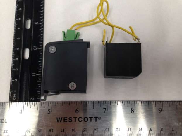
Click to zoom
Application Details
- Equipment Class
- DCD - Part 15 Low Power Transmitter Below 1705 kHz
- Date of Grant
- Jan 13, 2020
- Application Purpose
- Original Equipment
- Date of Application
- Jan 13, 2020
- Equipment Note
- Long Wire pet containment module
- Frequency Range
- 0.01500000 - 0.02500000
- Company
- Radio Systems Corp
- Country
- United States
Documents & Files
Document Text
Text extracted from the exhibit documents filed with the FCC. Open a document above to read the original.
Users Manual
Invisible Fence ® Brand Boundary Plus ® 2.0 Fence Field Test Plan Boundary Plus ® 2.0 System MVP-3 Field Test Plan BP 2.0 4-PORT HOST RIG00-16936 BP 2.0 COMPUTER COLLAR UNIT RIG00-16937 BP 2.0 LONG WIRE MODULE 10X RIG00-16947 BP 2.0 BATTERY MODULE RAC00-16946 BP 2.0 INDOOR SHIELDS ® WIRED RAC00-16949 BP 2.0 INDOOR SHIELDS ® WIRELESS RAC00-16950 BP 2.0 PROGRAMMING TOOL RAC00-16951 Invisible Fence ® Brand Boundary Plus ® 2.0 System Field Test Plan 2 of 20 U:\My Documents\Invisible Fence\Field Testing\Boundary Plus 2.0\Pre-Pilot-1\191002co Boundary Plus 2_0 Field Test Plan.docx 26 August 2019 1 Contents 1 Preface .................................................................................................................................................... 3 Field Testing .................................................................................................................................... 3 2 Introduction ............................................................................................................................................ 3 Product Description ......................................................................................................................... 3 Test Objectives ................................................................................................................................ 4 3 Field Test Timeline ................................................................................................................................ 5 Overview ......................................................................................................................................... 5 Timeline ........................................................................................................................................... 5 4 Setup and Operation Instructions ........................................................................................................... 6 Desktop App .................................................................................................................................... 6 Device Program Tools ..................................................................................................................... 6 Boundary Plus 2.0 Receiver and Battery Module ........................................................................... 6 4.3.1 Receiver Setup ......................................................................................................................... 7 Boundary Plus ® 2.0 4 Port Host Transmitter ................................................................................ 10 4.4.1 4 Port Host Transmitter and 2 Port Host Shields ® Transmitter Setup ................................... 11 5 Testing Protocol ................................................................................................................................... 13 Internal Testing .............................................................................................................................. 13 5.1.1 Tabletop Test .......................................................................................................................... 13 5.1.2 On Loop Test ......................................................................................................................... 16 External Testing – On Pet ............................................................................................................. 17 5.2.1 Initial Installation ................................................................................................................... 18 5.2.2 Bi-Weekly Check-in............................................................................................................... 19 6 Appendix .............................................................................................................................................. 19 Test Participants ............................................................................................................................ 19 Field Test Forms ............................................................................................................................ 20 6.2.1 Internal Test Form .................................................................................................................. 20 6.2.2 Install Form ............................................................................................................................ 20 6.2.3 Check-in Form ....................................................................................................................... 20 Invisible Fence ® Brand Boundary Plus ® 2.0 System Field Test Plan 3 of 20 U:\My Documents\Invisible Fence\Field Testing\Boundary Plus 2.0\Pre-Pilot-1\191002co Boundary Plus 2_0 Field Test Plan.docx 1 Preface Field Testing New products and updates to existing products must be developed, tested and iterated multiple times before being offered to customers. Field Testing is a critical step in the iteration cycle, helping to find flaws that would otherwise reach the end consumer. The purpose of Field Testing is to minimize risk, by making sure the product works as intended and as expected and to uncover limitations that can be mitigated through awareness and process implementation. Pro Staff members that do not fully complete the field test process conversely maximize risk to their dealership, RSC, the Invisible Fence ® Brand Network and ultimately the end consumer. THERE WILL BE FLAWS. There would be no reason to field test if everything was designed perfect the first time (or second or third time). Your job as a Pro Staff member is to do your best to find issues that can be addressed before the products are released to the network. It is not to complain about or give up on testing because issues are found. Testing takes time and effort. Waiting for others to complete testing then submitting forms when no testing or minim…
Text truncated - open the document above for the full version.
Cover Letter(s)
Radio Systems Corporation 10427 PetSafe Way, Knoxville, TN 37932 AGENCY AGREEMENT Federal Communications Commission Date: 7/31/2017 P.O. Box 429 Columbia, MD21045 Gentlemen: By signature below, we hereby appoint US Tech employees Sandi McEnery, Alan Ghasiani and George Yang to act as our agents with regard to all FCC equipment authorizations. This appointment will remain in effect until otherwise notified. I further certify by signature below that no party (per 47 CFR 1.2002(b)) to the application is subject to a denial of Federal benefits, including FCC benefits, pursuant to Section 5301 of the Anti-Drug Abuse Act of 1988, 21 U.S.C. 853(a). This appointment includes the authority to complete FCC Form 731 on our behalf and sign the application as an authorized agent. Name: Cindy Allen Signature: Title: Global Regulatory and Safety Manager Date:7/31/2017
Cover Letter(s)
Request for Confidentiality Date: December 20, 2019_____ Subject: Confidentiality Request for: ___FCC ID: KE3-3003590 IC: 2721A-3003590 Pursuant to FCC 47 CRF 0.457(d) and 0.459 and IC RSP-100, Section 12.4, the applicant requests that a part of the subject FCC application be held confidential. Type of Confidentiality Requested Exhibit Short Term Permanent Block Diagrams Short Term External Photos Short Term Permanent Internal Photos Short Term Permanent Operation Description/Theory of Operation Short Term Permanent Parts List & Placement/BOM Short Term Permanent Tune-Up Procedure Short Term Permanent Schematics Short Term Test Setup Photos Short Term Permanent* User’s Manual Radio Systems Corporation has spent substantial effort in developing this product and it is one of the first of its kind in industry. Having the subject information easily available to "competition" would negate the advantage they have achieved by developing this product. Not protecting the details of the design will result in financial hardship. Permanent Confidentiality: The applicant requests the exhibits listed above as permanently confidential be permanently withheld from public review due to materials that contain trade secrets and proprietary information not customarily released to the public. NOTE for Industry Canada Applications: The applicant understands that until such time that IC distinguishes between Short Term and Permanent Confidentiality, either type of marked exhibit above will simply be marked Confidential when submitted to IC. Sincerely, By:__________________________ Sandi McEnery__- Agent (Signature/Title) (Print name)
Cover Letter(s)
3505 Francis Circle Alpharetta, GA 30004 770-740-0717 www.ustech-lab.com MODULAR APPROVAL LETTER December 20, 2019 RE: Limited Modular Approval Request Grantee: Radio Systems Corporation FCC ID: KE3-3003590 Product: Boundary Plus 2.0 Long Wire Module 10X, Model RIG00-16947 Per the requirements, below, we request Limited Modular approval for the above referenced product Modular Approval Requirement Yes No (i) The radio elements of the modular transmitter must have their own shielding. The physical crystal and tuning capacitors may be located external to the shielded radio elements. - The transmitter does not have shielding over the transmitter circuits therefore the client is applying for a limited modular approval. The module will be limited to installation within Radio System Corp Model RIG00-16936, Boundary Plus 2.0 4-Port Transmitter host only and will be installed by only authorized Radio Systems personnel or authorized installer. x (ii) The modular transmitter must have buffered modulation/data inputs (if such inputs are provided) to ensure that the module will comply with part 15 requirements under conditions of excessive data rates or over-modulation. x (iii) The modular transmitter must have its own power supply regulation. x (iv) The modular transmitter must comply with the antenna and transmission system requirements of §§ 15.203, 15.204(b) and 15.204(c). The antenna must either be permanently attached or employ a ‘‘unique’’ antenna coupler (at all connections between the module and the antenna, including the cable). The ‘‘professional installation’’ provision of § 15.203 is not applicable to modules but can apply to limited modular approvals under paragraph (b) of this section. x (v) The modular transmitter must be tested in a stand-alone configuration x (vi) The modular transmitter must be equipped with either a permanently affixed label or must be capable of electronically displaying its FCC identification number. x (vii) The modular transmitter must comply with any specific rules or operating requirements that ordinarily apply to a complete transmitter and the manufacturer must provide adequate instructions along with the module to explain any such requirements. A copy of these instructions must be included in the application for equipment authorization. x (viii) The modular transmitter must comply with any applicable RF exposure requirements in its final configuration. x Sincerely, By:__________________________ Sandi McEnery__- Agent (Signature/Title) (Print name) 3505 Francis Circle Alpharetta, GA 30004 770-740-0717 www.ustech-lab.com
External Photos
US Tech Test Report: FCC Part 15 Certification/ RSS 210 FCC ID: KE3-3003590 IC: 2721A-3003590 Test Report Number: 19-0406 Issue Date: December 20, 2019 Customer: Radio Systems Model: RIG00-16947 Page 1 of 7 EXTERNAL PHOTOGRAPHS Figure 1. EUT Module with Inductor US Tech Test Report: FCC Part 15 Certification/ RSS 210 FCC ID: KE3-3003590 IC: 2721A-3003590 Test Report Number: 19-0406 Issue Date: December 20, 2019 Customer: Radio Systems Model: RIG00-16947 Page 2 of 7 Figure 2. EUT, Top US Tech Test Report: FCC Part 15 Certification/ RSS 210 FCC ID: KE3-3003590 IC: 2721A-3003590 Test Report Number: 19-0406 Issue Date: December 20, 2019 Customer: Radio Systems Model: RIG00-16947 Page 3 of 7 Figure 3. EUT, Bottom US Tech Test Report: FCC Part 15 Certification/ RSS 210 FCC ID: KE3-3003590 IC: 2721A-3003590 Test Report Number: 19-0406 Issue Date: December 20, 2019 Customer: Radio Systems Model: RIG00-16947 Page 4 of 7 Figure 4. EUT, Side 1 US Tech Test Report: FCC Part 15 Certification/ RSS 210 FCC ID: KE3-3003590 IC: 2721A-3003590 Test Report Number: 19-0406 Issue Date: December 20, 2019 Customer: Radio Systems Model: RIG00-16947 Page 5 of 7 Figure 5. EUT Side 2 US Tech Test Report: FCC Part 15 Certification/ RSS 210 FCC ID: KE3-3003590 IC: 2721A-3003590 Test Report Number: 19-0406 Issue Date: December 20, 2019 Customer: Radio Systems Model: RIG00-16947 Page 6 of 7 Figure 6. EUT Side 3 US Tech Test Report: FCC Part 15 Certification/ RSS 210 FCC ID: KE3-3003590 IC: 2721A-3003590 Test Report Number: 19-0406 Issue Date: December 20, 2019 Customer: Radio Systems Model: RIG00-16947 Page 7 of 7 Figure 7. EUT Side 4
ID Label/Location Info
US Tech Test Report: FCC Part 15/ISED RSS-210 Report Number: 19-0406 Issue Date: December 20, 2019 Customer: Radio Systems Corporation Model(s): RIG00-16947 FCC ID: KE3-3003590 IC: 2721A-3003590 SAMPLE LABEL Figure 1. Sample Label and Location
Internal Photos
US Tech Test Report: FCC Part 15 Certification/ RSS 210 FCC ID: KE3-3003590 IC: 2721A-3003590 Test Report Number: 19-0406 Issue Date: December 20, 2019 Customer: Radio Systems Model: RIG00-16947 INTERNAL PHOTOGRAPHS Figure 1. Module Board - Top US Tech Test Report: FCC Part 15 Certification/ RSS 210 FCC ID: KE3-3003590 IC: 2721A-3003590 Test Report Number: 19-0406 Issue Date: December 20, 2019 Customer: Radio Systems Model: RIG00-16947 Figure 2. Module Board - Bottom
Test Report
Page 1 of 23 Application For Title 47 USC Part 2, Subpart J, Paragraph 2.907 Equipment Authorization of Certification for an Intentional Radiator per Part 15, Subpart C, Paragraphs 15.207 and 15.209 And Industry Canada, Radio Standards Specifications: RSS Gen Issue 5 and RSS-210 Issue 9 For the Radio Systems Long Wire Module 10X Model: RIG00-16947 FCC ID: KE3-3003590 IC: 2721A-3003590 UST Project: 19-0406 Test Date: November 11-22, 2019 Report Issue Date: December 20, 2019 Total Pages in This Report : 23 3505 Francis Circle Alpharetta, GA 30004 PH: 770-740-0717 Fax: 770-740-1508 www.ustech-lab.com Page 2 of 23 I certify that I am authorized to sign for the Test Agency and that all of the statements in this report and in the Exhibits attached hereto are true and correct to the best of my knowledge and belief: US TECH (Agent Responsible For Test): By: Alan Ghasiani Name: Title: Compliance Engineer – President Date December 20, 2019 This report shall not be reproduced except in full. This report may be copied in part only with the prior written approval of US Tech. The results contained in this report are subject to the adequacy and representative character of the sample provided. This report must not be used to claim product certification, approval, or endorsement by NVLAP, NIST or any agency of the Federal Government. 3505 Francis Circle Alpharetta, GA 30004 PH: 770-740-0717 Fax: 770-740-1508 www.ustech-lab.com US Tech Test Report: FCC Part 15 Certification/ RSS 210 FCC ID: KE3-3003590 IC: 2721A-3003590 Test Report Number: 19-0406 Issue Date: December 20, 2019 Customer: Radio Systems Model: RIG00-16947 Page 3 of 23 MEASUREMENT TECHNICAL REPORT COMPANY NAME: Radio Systems 10427 Petsafe Way Knoxville, TN 37932 MODEL: RIG00-16947 FCC ID: KE3-3003590 IC: 2721A-3003590 DATE: December 20, 2019 This report concerns (check one): Original grant X Class II change Equipment type: Low Power Transmitter Module (9 kHz -30 MHz) Deferred grant requested per 47 CFR 0.457(d)(1)(ii)? yes_____ No X If yes, defer until: ______N/A___________ date agrees to notify the Commission by N/A date of the intended date of announcement of the product so that the grant can be issued on that date. Report prepared by: US Tech 3505 Francis Circle Alpharetta, GA 3000 Phone Number: (770) 740-0717 Fax Number: (770) 740-1508 US Tech Test Report: FCC Part 15 Certification/ RSS 210 FCC ID: KE3-3003590 IC: 2721A-3003590 Test Report Number: 19-0406 Issue Date: December 20, 2019 Customer: Radio Systems Model: RIG00-16947 Page 4 of 23 Table of Contents Paragraph Title Page 1 General Information .......................................................................................... 6 1.1 Purpose of this Report .................................................................................. 6 1.2 Characterization of Test Sample ................................................................... 6 1.3 Product Description ...................................................................................... 6 1.4 Configuration of Tested System .................................................................... 6 1.5 Test Facility ................................................................................................... 7 2 Tests and Measurements ................................................................................. 9 2.1 Test Equipment ............................................................................................. 9 2.2 Modifications to EUT Hardware .................................................................... 9 2.3 Number of Measurements for Intentional Radiators (15.31(m)) .................. 10 2.4 Frequency Range of Radiated Measurements (Part 15.33)........................ 10 2.4.1 Intentional Radiator ................................................................................. 10 2.4.2 Unintentional Radiator ............................................................................. 10 2.5 Measurement Detector Function and Bandwidth (CFR 15.35) ................... 11 2.6 EUT Antenna Requirements (CFR 15.203) ................................................ 11 2.7 Restricted Bands of Operation (Part 15.205) .............................................. 12 2.8 Intentional Radiator, Power Line Conducted Emissions (CFR 15.207) ....... 13 2.9 Intentional Radiator, Radiated Emissions (CFR 15.209, (IC RSS 210)) ..... 13 2.10 99% Occupied Bandwidth (IC RSS 210, A8.1) ........................................... 14 2.11 Unintentional/Intentional Radiator, Power line Emissions (CFR 15.107 and 15.207) ................................................................................................................. 15 2.12 Unintentional/Intentional Radiator, Radiated Emissions (CFR 15.109 and 15.209) ................................................................................................................. 17 2.13 Radiated Emission Limits - General Requirements ................................. 18 2.14 Measurement Uncertainty .......................................................................... 23 2.14.1 Conducted Emissions Measurement Uncertainty ................................. 23 2.14.2 Radiated Emissions Measurement Uncertainty .................................... 23 US Tech Test Report: FCC Part 15 Certification/ RSS 210 FCC ID: KE3-3003590 IC: 2721A-3003590 Test Report Number: 19-0406 Issue Date: December 20, 2019 Customer: Radio Systems Model: RIG00-16947 Page 5 of 23 List of Figures Figures Title Page Figure 1. Block Diagram of Test Configuration (intentional) ..................................... 12 Figure 2. Block Diagram of Test Configuration (unintentional) ................................. 12 Figure 3. 99% Bandwidth ......................................................................................... 15 Figure 4. Radiated Emissions Graphical Data, 30 - 1000 MHz – Horizontal ............ 22 Figure 5. Radiated Emissions Graphical Data, 30 - 1000 MHz – Vertical .....…
Text truncated - open the document above for the full version.
Test Setup Photos
US Tech Test Report: FCC Part 15 Certification/ RSS 210 FCC ID: KE3-3003590 IC: 2721A-3003590 Test Report Number: 19-0406 Issue Date: December 20, 2019 Customer: Radio Systems Model: RIG00-16947 Page 1 of 12 Test Configuration Photographs Figure 1. Radiated Emissions Test Setup, Close-Up US Tech Test Report: FCC Part 15 Certification/ RSS 210 FCC ID: KE3-3003590 IC: 2721A-3003590 Test Report Number: 19-0406 Issue Date: December 20, 2019 Customer: Radio Systems Model: RIG00-16947 Page 2 of 12 Figure 2. Close-Up of EUT on Table, showing Wire Loop Antenna US Tech Test Report: FCC Part 15 Certification/ RSS 210 FCC ID: KE3-3003590 IC: 2721A-3003590 Test Report Number: 19-0406 Issue Date: December 20, 2019 Customer: Radio Systems Model: RIG00-16947 Page 3 of 12 Figure 3. Radiated Emissions Test Setup, 9 kHz to 30 MHz (Normal Operation) US Tech Test Report: FCC Part 15 Certification/ RSS 210 FCC ID: KE3-3003590 IC: 2721A-3003590 Test Report Number: 19-0406 Issue Date: December 20, 2019 Customer: Radio Systems Model: RIG00-16947 Page 4 of 12 Figure 4. Radiated Emissions Test Setup, 30 MHz to 200 MHz (Radio Test with EUT in worst case position) US Tech Test Report: FCC Part 15 Certification/ RSS 210 FCC ID: KE3-3003590 IC: 2721A-3003590 Test Report Number: 19-0406 Issue Date: December 20, 2019 Customer: Radio Systems Model: RIG00-16947 Page 5 of 12 Figure 5. Radiated Emissions Test Setup, 200 MHz to 1 GHz (Radio Test with EUT in worst case position) US Tech Test Report: FCC Part 15 Certification/ RSS 210 FCC ID: KE3-3003590 IC: 2721A-3003590 Test Report Number: 19-0406 Issue Date: December 20, 2019 Customer: Radio Systems Model: RIG00-16947 Page 6 of 12 Figure 6. Radiated Emissions Test Setup, Above 1 GHz (Radio Test with EUT in worst case position) US Tech Test Report: FCC Part 15 Certification/ RSS 210 FCC ID: KE3-3003590 IC: 2721A-3003590 Test Report Number: 19-0406 Issue Date: December 20, 2019 Customer: Radio Systems Model: RIG00-16947 Page 7 of 12 Figure 7. EUT above 1 GHz Test Configuration (Intentional Emissions) US Tech Test Report: FCC Part 15 Certification/ RSS 210 FCC ID: KE3-3003590 IC: 2721A-3003590 Test Report Number: 19-0406 Issue Date: December 20, 2019 Customer: Radio Systems Model: RIG00-16947 Page 8 of 12 Figure 8. Frequency Stability Test Setup US Tech Test Report: FCC Part 15 Certification/ RSS 210 FCC ID: KE3-3003590 IC: 2721A-3003590 Test Report Number: 19-0406 Issue Date: December 20, 2019 Customer: Radio Systems Model: RIG00-16947 Page 9 of 12 Figure 9. Frequency Stability Test Close-Up US Tech Test Report: FCC Part 15 Certification/ RSS 210 FCC ID: KE3-3003590 IC: 2721A-3003590 Test Report Number: 19-0406 Issue Date: December 20, 2019 Customer: Radio Systems Model: RIG00-16947 Page 10 of 12 Figure 10. Substitution Testing 30-200 MHz US Tech Test Report: FCC Part 15 Certification/ RSS 210 FCC ID: KE3-3003590 IC: 2721A-3003590 Test Report Number: 19-0406 Issue Date: December 20, 2019 Customer: Radio Systems Model: RIG00-16947 Page 11 of 12 Figure 11. Substitution Testing 200 - 1000 MHz US Tech Test Report: FCC Part 15 Certification/ RSS 210 FCC ID: KE3-3003590 IC: 2721A-3003590 Test Report Number: 19-0406 Issue Date: December 20, 2019 Customer: Radio Systems Model: RIG00-16947 Page 12 of 12 Figure 12. Substitution Testing above 1 GHz
Contact Information
Applicant
Deborah J. LeMaster(Regulatory Compliance Specialist)
Test Firm
US TechGeorge Yang
Technical Specifications
| # | Rule Parts | Frequency Range | Power Output |
|---|---|---|---|
| 1 | 15C | 0.015 MHz - 0.025 MHz | - |
Other Applications from Radio Systems Corp

KE3-PIF150-2
Jun 18, 2026Stay & Play Wireless Fence
Equipment Class
DCD - Part 15 Low Power Transmitter Below 1705 kHz
KE3-3003841
Jun 05, 2026PetSafe HydroSphere 60 oz Cordless Fountain
Equipment Class
FDS - Part 15 Field Disturbance Sensor
KE3-3003832
Apr 08, 2026GPS Tracker Collar
Equipment Class
DTS - Digital Transmission System
KE3-3003791
Jul 01, 2024MURS radio device
Equipment Class
TNB - Licensed Non-Broadcast Station Transmitter
KE3-3003803
Apr 06, 2024Dog Training Collar
Equipment Class
DSC - Part 15 Security/Remote Control Transmitter