KE3-3003679MURS radio device
Radio Systems Corp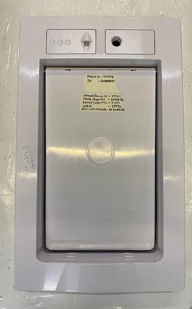
Click to zoom
Application Details
- Equipment Class
- TNB - Licensed Non-Broadcast Station Transmitter
- Date of Grant
- Nov 12, 2020
- Application Purpose
- Original Equipment
- Date of Application
- Nov 12, 2020
- Equipment Note
- MURS radio device
- Frequency Range
- 151.82000000 - 151.82000000
- Company
- Radio Systems Corp
- Country
- United States
Documents & Files
Document Text
Text extracted from the exhibit documents filed with the FCC. Open a document above to read the original.
Users Manual
Invisible Fence® Brand Smart™ Doorman™ Owner’s Manual Important Precautions Invisible Fence® Brand pet containment systems have contained over three million pets. However, there are some precautions you should take. Read and retain manuals Adhere to all warnings and cautions contained in any Invisible Fence® Brand manual. WARNING When children are present in the home, it is important to consider the pet door during child proofing activities. The pet door may be misused by a child resulting in the child accessing potential hazards that may be on the other side of the pet door. Purchasers/Homeowners with swimming pools should ensure that the pet door is monitored at all times and that the swimming pool has adequate barriers to entry. If a new hazard is created inside or outside of your home, which may be accessed through the pet door, Invisible Fence® Brand recommends that you properly guard access to the hazard or remove the pet door. The closing panel or lock, if applicable, is provided for aesthetic and energy efficiency purposes and is not intended as a security device. Invisible Fence® Brand will not be liable for unintended use and the purchaser of this product accepts full responsibility for oversight of the opening it creates. CAUTION This pet door is not a fire door. It is important for the owner and contractor to consider any risks that may be present inside or outside of the pet door, and any risks that may be created by subsequent changes to your property and how they may relate to the existence and use, including misuse of the pet door. NOTICE The user, prior to installation, must become familiar with all building codes that may affect the installation of the pet door and determine, along with a licensed contractor, its suitability in a given installation. Keep these instructions with important papers; be sure to transfer these instructions to the new owner of the property. Unauthorized changes or modifications may void the user’s authority to operate this equipment and void the warranty. 1-Year Limited Warranty - The Invisible Fence® Brand Doorman™ is warranted against manufacture defects for a period of one (1) year from the date of original purchase at retail. Proof of purchase may be required. Does not include gross neglect or abuse. Which includes but is not limited to dog chews, pet scratches, and damage caused by improper use. Thank you for choosing the Invisible Fence® Brand Doorman™ Electronic Pet Door. You and your pet deserve a companionship that includes memorable moments and a shared understanding together. Our products and training tools promote a lifestyle of protection, teaching, and love—essentials that influence memories for a lifetime. If you have any questions about our products or training your pet, please visit our website at www. invisiblefence.com or contact your local dealer. How the Smart™ Doorman™ Pet Door Works Using radio-frequency technology, the Invisible Fence® Brand Smart™ Doorman™ pet door reads the Computer Collar® SmartLink™ signal and triggers the flap to unlock so the pet(s) can come and go as they please. When the door no longer senses the pets’ Computer Collar®; the flap automatically locks back into place. Controls & Features Features: The Invisible Fence® Brand Smart™ Doorman™ contains a variety of features and abilities that can be controlled and configured by users Switch between Locked, Unlocked and Automatic modes View Low Battery Indicator Set Signal Activation Range Function Change frequencies settings (15k, 20k, 25k) Controls Push Buttons: There are 3 push button switches available for users to control the door mode. The buttons are called Auto/Lock/Unlock Modes: Pressing the Lock/Unlock/Auto button will cause the pet door to transition to one of the three available modes: Auto (dog head) When the pet door is placed in Auto mode, it is automatically locked and will only unlock when a programmed Computer Collar comes within proximity of the pet door. The pet door will relock automatically when all programmed collars are out of range for 10 seconds. Locked (closed lock) When the pet door is set to Locked mode, the pet door will lock and remain in that mode until the next schedule interval occurs (if Schedule is on) or when the Lock/ Unlock/Auto button is pressed. When this mode is selected a programmed Computer Collar has no effect on the pet door. Unlocked (open lock) When the pet door is set to Unlocked mode, the pet door will unlock and remain in that mode until a new mode is selected. When this mode is selected a programmed Computer Collar® has no effect on the pet door. If the pet door fails to set to the selected mode, there are 3 possible reasons why the pet door may fail to establish the connection High door motor current (motor turning is being hindered in some way) Pet door time out (it took more than 18 seconds to transition to the specified mode) Pet door jams (the door is unable to close, usually caused by an obstruction) Set-Up Place rechargeable battery in large open battery slot on right side of door as you face it. Optional Power adapter (RAC00-13701) can be used in addition to the battery operation. Press Lock/Unlock/Auto button for desired mode Terms of Use and Limitation of Liability TERMS OF USE This Product is offered to you conditioned upon your acceptance without modification of the terms, conditions and notices contained herein. Usage of this Product implies acceptance of all such terms, conditions, and notices. PROPER USE This Product is designed for use with pets where training is desired. The specific temperament of your pet may not work with this Product. If you are unsure whether this is appropriate for your pet, please consult your veterinarian or certified trainer. Proper use includes reviewing the entire Operating Guide provided with your Product and any specific Caution statements. NO UNLAWFUL OR PROHIBITED USE This Product is designed for use with…
Text truncated - open the document above for the full version.
Attestation Statements
3505 Francis Circle Alpharetta, GA 30004 PH: 770-740-0717 www.ustech-lab.com October 29, 2020 SDOC ATTESTATION LETTER RE: Radio Systems Corporation, FCC: KE3-3003679 and IC: 2721A-3003679 On behalf of Radio Systems Corporation, we attest that SDoC Testing and a report have been completed for the Model RAC00-17202. The product meets all requirements and the report is on file and available for review if requested. Best Regards, Sandi McEnery Radio Systems Corporation
Cover Letter(s)
Radio Systems Corporation 10427 PetSafe Way, Knoxville, TN 37932 AGENCY AGREEMENT Federal Communications Commission Date: 7/31/2017 P.O. Box 429 Columbia, MD21045 Gentlemen: By signature below, we hereby appoint US Tech employees Sandi McEnery, Alan Ghasiani and George Yang to act as our agents with regard to all FCC equipment authorizations. This appointment will remain in effect until otherwise notified. I further certify by signature below that no party (per 47 CFR 1.2002(b)) to the application is subject to a denial of Federal benefits, including FCC benefits, pursuant to Section 5301 of the Anti-Drug Abuse Act of 1988, 21 U.S.C. 853(a). This appointment includes the authority to complete FCC Form 731 on our behalf and sign the application as an authorized agent. Name: Cindy Allen Signature: Title: Global Regulatory and Safety Manager Date:7/31/2017
Cover Letter(s)
Request for Confidentiality Date: October 30, 2020 Subject: Confidentiality Request for: FCC ID: KE3-3003679, IC: 2721A-3003679 Pursuant to FCC 47 CRF 0.457(d) and 0.459 and IC RSP-100, Section 12.4, the applicant requests that a part of the subject application be held confidential. Type of Confidentiality Requested Exhibit Short Term Permanent Block Diagrams Short Term Permanent External Photos Short Term Permanent Internal Photos Short Term Permanent Operation Description/Theory of Operation Short Term Permanent Parts List & Placement/BOM Short Term Permanent Tune-Up Procedure Short Term Permanent Schematics Short Term Permanent Test Setup Photos Short Term Permanent* User’s Manual Radio Systems Corporation has spent substantial effort in developing this product and it is one of the first of its kind in industry. Having the subject information easily available to "competition" would negate the advantage they have achieved by developing this product. Not protecting the details of the design will result in financial hardship. Permanent Confidentiality: The applicant requests the exhibits listed above as permanently confidential be permanently withheld from public review due to materials that contain trade secrets and proprietary information not customarily released to the public. NOTE for Industry Canada Applications: The applicant understands that until such time that ISED distinguishes between Short Term and Permanent Confidentiality, either type of marked exhibit above will simply be marked Confidential when submitted to ISED. Sincerely, By:______________________ Sandi McEnery- Agent (Signature) (Print name/Title)
External Photos
US Tech Test Report: FCC Part 15, 95 and ISED RSS 210 FCC ID: KE3-3003679 IC: 2721A-3003679 Test Report Number: 20-0276 Issue Date: October 30, 2020 Customer: Radio Systems Corporation Model: RAC00-17202 Page 1 of 4 EXTERNAL PHOTOGRAPHS Figure 1. RAC00-17202 – Front US Tech Test Report: FCC Part 15, 95 and ISED RSS 210 FCC ID: KE3-3003679 IC: 2721A-3003679 Test Report Number: 20-0276 Issue Date: October 30, 2020 Customer: Radio Systems Corporation Model: RAC00-17202 Page 2 of 4 Figure 2. RAC00-17202 – Back US Tech Test Report: FCC Part 15, 95 and ISED RSS 210 FCC ID: KE3-3003679 IC: 2721A-3003679 Test Report Number: 20-0276 Issue Date: October 30, 2020 Customer: Radio Systems Corporation Model: RAC00-17202 Page 3 of 4 Figure 3. RAC00-17202 – Side 1 Figure 4. RAC00-17202 – Side 2 US Tech Test Report: FCC Part 15, 95 and ISED RSS 210 FCC ID: KE3-3003679 IC: 2721A-3003679 Test Report Number: 20-0276 Issue Date: October 30, 2020 Customer: Radio Systems Corporation Model: RAC00-17202 Page 4 of 4 Figure 5. RAC00-17202 – Top Figure 6. RAC00-17202 – Bottom
ID Label/Location Info
US Tech Test Report: FCC Part 15 Certification/ RSS 210 FCC ID: KE3-3003679 IC: 2721A-3003679 Test Report Number: 20-0274 Issue Date: October 29, 2020 Customer: Radio Systems Corporation Model: RAC00-17202 Page 1 of 2 Sample Label Figure 1. Label Placement on EUT Module FCC ID: KE3-3003679 IC: 2721A-3003679 Model/ Modele: RAC00-1702 Input 5V ---- 0.5A Made in Vietnam/ Fabrique au Vietnam Radio Systems Corporation (IFB Serial Number) (Module Serial Number) US Tech Test Report: FCC Part 15 Certification/ RSS 210 FCC ID: KE3-3003679 IC: 2721A-3003679 Test Report Number: 20-0274 Issue Date: October 29, 2020 Customer: Radio Systems Corporation Model: RAC00-17202 Page 2 of 2 Figure 2. Label Visible after Installation in Doorframe FCC ID: KE3-3003679 IC: 2721A-3003679 Model/ Modele: RAC00-1702 Input 5V ---- 0.5A Made in Vietnam/ Fabrique au Vietnam Radio Systems Corporation (IFB Serial Number) (Module Serial Number)
Internal Photos
US Tech Test Report: FCC Part 15, 95, ISED RSS 210 FCC ID: KE3-3003679 IC: 2721A-300-3679 Test Report Number: 20-0276 Issue Date: October 30, 2020 Customer: Radio Systems Model: RAC00-17202 Page 1 of 6 INTERNAL PHOTOGRAPHS Figure 1. RAC00-17202 with Cover Removed US Tech Test Report: FCC Part 15, 95, ISED RSS 210 FCC ID: KE3-3003679 IC: 2721A-300-3679 Test Report Number: 20-0276 Issue Date: October 30, 2020 Customer: Radio Systems Model: RAC00-17202 Page 2 of 6 Figure 2. RAC00-17202 with Electronic Module lifted US Tech Test Report: FCC Part 15, 95, ISED RSS 210 FCC ID: KE3-3003679 IC: 2721A-300-3679 Test Report Number: 20-0276 Issue Date: October 30, 2020 Customer: Radio Systems Model: RAC00-17202 Page 3 of 6 Figure 3. Electronic Module removed (Rear) US Tech Test Report: FCC Part 15, 95, ISED RSS 210 FCC ID: KE3-3003679 IC: 2721A-300-3679 Test Report Number: 20-0276 Issue Date: October 30, 2020 Customer: Radio Systems Model: RAC00-17202 Page 4 of 6 Figure 4. Electronic Module (Front) US Tech Test Report: FCC Part 15, 95, ISED RSS 210 FCC ID: KE3-3003679 IC: 2721A-300-3679 Test Report Number: 20-0276 Issue Date: October 30, 2020 Customer: Radio Systems Model: RAC00-17202 Page 5 of 6 Figure 5. RAC00-17202 – Main PCB (Front Side) Figure 6. RAC00-17202 – Main PCB (Back Side) US Tech Test Report: FCC Part 15, 95, ISED RSS 210 FCC ID: KE3-3003679 IC: 2721A-300-3679 Test Report Number: 20-0276 Issue Date: October 30, 2020 Customer: Radio Systems Model: RAC00-17202 Page 6 of 6 Figure 7. RAC00-17202 – Electronic Module PCB (Front side) Figure 8. Electronic Module PCB (Back side)
RF Exposure Info
US Tech Test Report: FCC Part 15 Certification/ RSS 210 FCC ID: KE3-3003679 IC: 2721A-3003679 Test Report Number: 20-0276 Issue Date: October 30, 2020 Customer: Radio Systems Corporation Model: RAC00-17202 Page 1 of 1 Maximum Public Exposure to RF (MPE), CFR 1.1310 (e) General SAR test exclusion per KDB 447498 D01 V06 section 4.3 Test exclusion conditions are based on source-based time averaged maximum conducted output power of the RF channel, adjusted for tune-up tolerance, and the minimum test separation distance required for the exposure conditions. For 100 MHz to 6 GHz and test separation distances ≤ 50 mm, the 1-g and 10-g SAR test exclusion thresholds are determined by the following: [(max. power of channel mW) / (min. test separation distance, mm)] * [(√f GHz )] Where the result must be ≤ 3.0 for 1-g SAR and ≤ 7.0 for 10-g SAR EUT source based time averaged (SBTA) = (output power + antenna gain * duty cycle) SBTA= +16.0 dBm (worst case output pwr) + -19.0 dBm (antenna gain) + 1.0 (worst case Duty Cycle) = -3.0 dBm = 0.5 mW 0.5 mW/50 mm * (√0.15182 GHz) = 0.004 << 3.0 for 1-g SAR and ≤ 7.0 for 10-g SAR
Test Report
Page 1 of 20 Report of Title 47 CFR Part 95 Subpart J, Multi User Radio Services (MURS) and TIA-603-E (2016) Land Mobile FM or PM- Communications Equipment Measurement and Performance Standard For the Radio Systems Corporation Invisible Fence Brand Smart Doorman 2.0 Model: RAC00-17202 FCC ID: KE3-3003679 Issue Date: October 30, 2020 Test Dates: October 19, 20 & 22, 2020 UST Project No.: 20-0276 Total Number of Pages Contained in this Report: 20 3505 Francis Circle Alpharetta, GA 30004 PH: 770-740-0717 Fax: 770-740-1508 www.ustech-lab.com Page 2 of 20 I, George Yang, certify that I am authorized to sign for the test facility and that all of the statements in this report and in the exhibits attached hereto are true and correct to the best of my knowledge and belief: US TECH (Agent Responsible For Test): By: ____________________ Name: George Yang Title: Laboratory Manager Date: October 30, 2020 This report shall not be reproduced except in full. This report may be copied in part only with the prior written approval of US Tech. The results contained in this report are subject to the adequacy and representative character of the sample provided. US Tech’s NVLAP accreditation does not allow product endorsement by NVLAP or any agency of the U.S. Government. 3505 Francis Circle Alpharetta, GA 30004 PH: 770-740-0717 Fax: 770-740-1508 www.ustech-lab.com US Tech Test Report: FCC Part 95 Report Number: 20-0276 Issue Date: October 30, 2020 Customer: Radio Systems Corporation Model: RAC00-17202 FCC ID: KE3-3003679 Page 3 of 20 Table of Contents Paragraph Title Page 1 General Information ............................................................................................... 5 1.1 Product Description ............................................................................................ 5 1.2 Related Submittal(s)/Grant(s)............................................................................. 5 1.3 Test Methodology ............................................................................................... 6 1.4 Test Facility ........................................................................................................ 6 1.4.1 Radiated Emissions Test Site (Shielded Semi Anechoic EMC Chamber) ... 6 1.5 Test Equipment .................................................................................................. 8 1.6 Modifications to EUT .......................................................................................... 8 2 Output Power........................................................................................................ 12 2.1 Maximum Transmitter Power (FCC 2.1046 & 95.2767) ................................ 12 2.1.1 Maximum Power Allowed .......................................................................... 12 2.1.2 Measured Fundamental Signal .................................................................. 13 3 Emissions Bandwidth (Part 95.2773(a)) ............................................................. 14 3.1 Maximum Authorized Bandwidth ...................................................................... 14 4 MURS Unwanted Radiation Emissions(CFR 95.2779) ....................................... 15 4.1 Test Method ........................................................................................................ 15 4.2 FCC Limits ......................................................................................................... 15 4.3 Test Results ........................................................................................................ 15 5 Field Strength of Spurious Radiation, (FCC 2.1051 & 95.2779(b)(2)) ............... 17 5.1 Test Method ..................................................................................................... 17 5.2 FCC Limits ....................................................................................................... 17 5.3 Test Results ..................................................................................................... 18 6 Frequency Stability (CFR 2.1055, 95.2765) ........................................................ 19 6.1 Test Method ..................................................................................................... 19 6.2 FCC Limits ....................................................................................................... 19 6.3 Test Results ..................................................................................................... 20 US Tech Test Report: FCC Part 95 Report Number: 20-0276 Issue Date: October 30, 2020 Customer: Radio Systems Corporation Model: RAC00-17202 FCC ID: KE3-3003679 Page 4 of 20 List of Figures Figure Title Page Figure 1. Radiated Emissions Disturbance Measurement Facility Diagram .................... 7 Figure 2. EUT Test Configuration – Radiated Emissions ................................................ 9 Figure 3. EUT Test Configuration - AC Power Line Conducted Emissions .................. 10 Figure 4. Bandwidth Measurement ............................................................................... 14 Figure 5. Emission Mask ............................................................................................... 16 List of Tables Table Title Page Table 1. Test Instruments ................................................................................................ 8 Table 2. EUT and Peripherals ....................................................................................... 11 Table 3. Antennas ......................................................................................................... 11 Table 4. Maximum Output Power .................................................................................. 13 Table 5. Field Strength of Spurious Radiation ............................................................... 18 Table 6. Frequency Deviation/Stability .......................................................................... 20 US Tech…
Text truncated - open the document above for the full version.
Test Setup Photos
US Tech Test Report: FCC Part 15 Certification/ RSS 210 FCC ID: KE3-3003679 IC: 2721A-3003679 Test Report Number: 20-0276 Issue Date: October 28, 2020 Customer: Radio Systems Corporation Model: RAC00-17202 Page 1 of 7 TEST CONFIGURATION PHOTOGRAPHS Figure 1. Radiated Emissions Test Setup, Close-up US Tech Test Report: FCC Part 15 Certification/ RSS 210 FCC ID: KE3-3003679 IC: 2721A-3003679 Test Report Number: 20-0276 Issue Date: October 28, 2020 Customer: Radio Systems Corporation Model: RAC00-17202 Page 2 of 7 Figure 2. Radiated Emissions Test Setup, 9 kHz to 30 MHz US Tech Test Report: FCC Part 15 Certification/ RSS 210 FCC ID: KE3-3003679 IC: 2721A-3003679 Test Report Number: 20-0276 Issue Date: October 28, 2020 Customer: Radio Systems Corporation Model: RAC00-17202 Page 3 of 7 Figure 3. Radiated Emissions Test Setup, 30 MHz to 200 MHz US Tech Test Report: FCC Part 15 Certification/ RSS 210 FCC ID: KE3-3003679 IC: 2721A-3003679 Test Report Number: 20-0276 Issue Date: October 28, 2020 Customer: Radio Systems Corporation Model: RAC00-17202 Page 4 of 7 Figure 4. Radiated Emissions Test Setup, 200 MHz to 1GHz US Tech Test Report: FCC Part 15 Certification/ RSS 210 FCC ID: KE3-3003679 IC: 2721A-3003679 Test Report Number: 20-0276 Issue Date: October 28, 2020 Customer: Radio Systems Corporation Model: RAC00-17202 Page 5 of 7 Figure 5. Radiated Emission Test Setup, above 1 GHz US Tech Test Report: FCC Part 15 Certification/ RSS 210 FCC ID: KE3-3003679 IC: 2721A-3003679 Test Report Number: 20-0276 Issue Date: October 28, 2020 Customer: Radio Systems Corporation Model: RAC00-17202 Page 6 of 7 Figure 6. Conducted Emissions Test Setup US Tech Test Report: FCC Part 15 Certification/ RSS 210 FCC ID: KE3-3003679 IC: 2721A-3003679 Test Report Number: 20-0276 Issue Date: October 28, 2020 Customer: Radio Systems Corporation Model: RAC00-17202 Page 7 of 7 Figure 7. Frequency Stability Test Setup
Contact Information
Applicant
Deborah J. LeMaster(Regulatory Compliance Specialist)
Test Firm
US TechGeorge Yang
Technical Specifications
| # | Rule Parts | Frequency Range | Power Output | Emission | Tolerance |
|---|---|---|---|---|---|
| 1 | 95J | 151.82 MHz - 151.82 MHz | 2.00 mW | 6K13F2D | 5.0000000000 ppm |
Other Applications from Radio Systems Corp

KE3-PIF150-2
Jun 18, 2026Stay & Play Wireless Fence
Equipment Class
DCD - Part 15 Low Power Transmitter Below 1705 kHz
KE3-3003841
Jun 05, 2026PetSafe HydroSphere 60 oz Cordless Fountain
Equipment Class
FDS - Part 15 Field Disturbance Sensor
KE3-3003832
Apr 08, 2026GPS Tracker Collar
Equipment Class
DTS - Digital Transmission System
KE3-3003791
Jul 01, 2024MURS radio device
Equipment Class
TNB - Licensed Non-Broadcast Station Transmitter
KE3-3003803
Apr 06, 2024Dog Training Collar
Equipment Class
DSC - Part 15 Security/Remote Control Transmitter