KE3-300741TRANSMITTER FOR PET BOUNDARY SYSTEM
Radio Systems Corp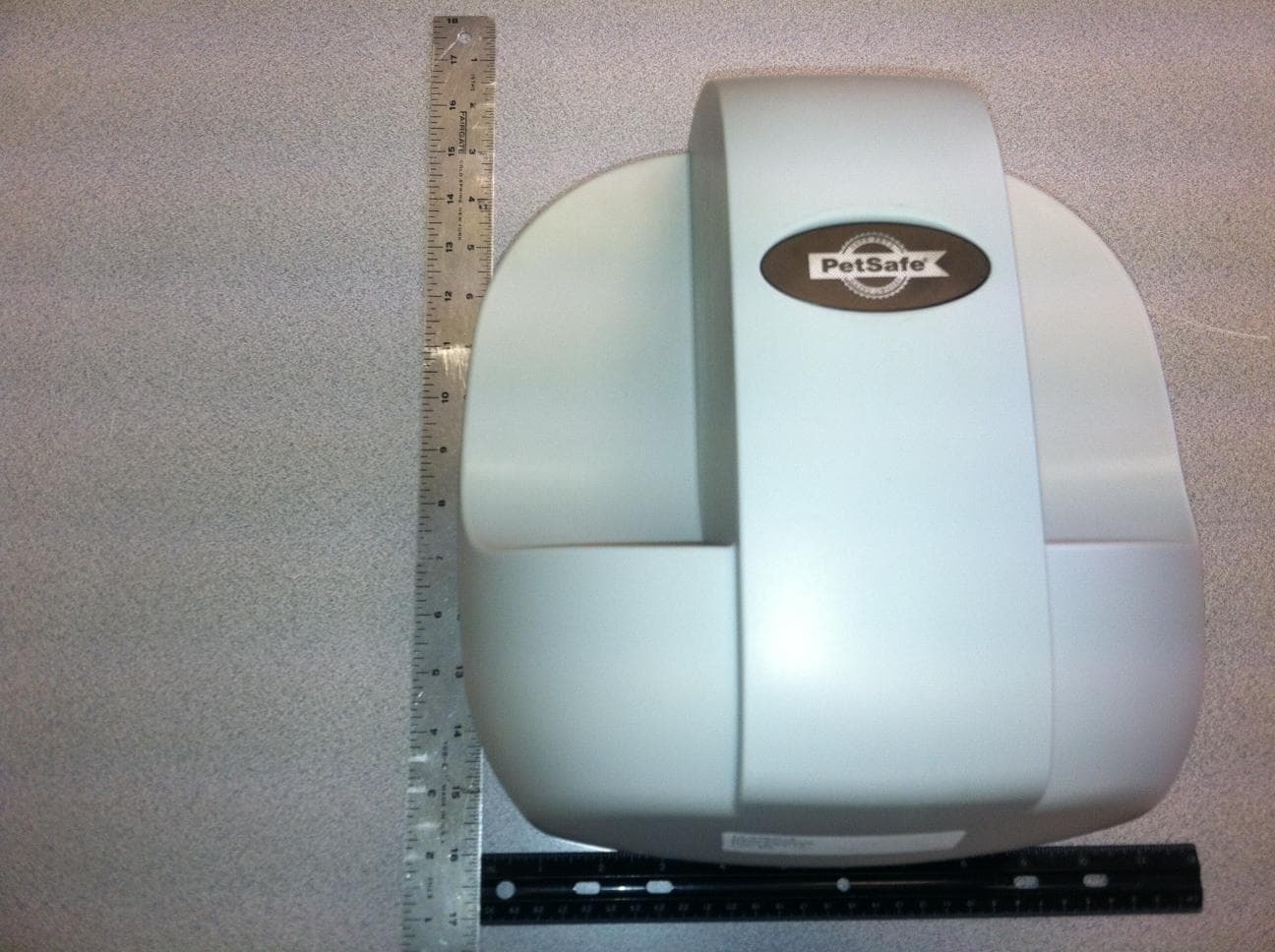
Click to zoom
Application Details
- Equipment Class
- DCD - Part 15 Low Power Transmitter Below 1705 kHz
- Date of Grant
- Oct 01, 2012
- Application Purpose
- Original Equipment
- Date of Application
- Oct 01, 2012
- Equipment Note
- TRANSMITTER FOR PET BOUNDARY SYSTEM
- Frequency Range
- 0.02730000 - 0.02772000
- Company
- Radio Systems Corp
- Country
- United States
Documents & Files
Document Text
Text extracted from the exhibit documents filed with the FCC. Open a document above to read the original.
Users Manual
paw point custom wireless fence operating and training guide Model Number PIF00-13651 PLEASE READ THIS ENTIRE GUIDE BEFORE BEGINNING 2 1-800-732-2677 Important Safety Information Explanation of Attention Words and Symbols used in this guide This is the safety alert symbol. It is used to alert you to potential personal injury hazards. Obey all safety messages that follow this symbol to avoid possible injury or death. WARNING indicates a hazardous situation which, if not avoided, could result in death or serious injury. CAUTION, used without the safety alert symbol, indicates a hazardous situation which, if not avoided, could result in harm to your pet. NOTICE is used to address safe use practices not related to personal injury. • Not for use with aggressive dogs. Do not use this product if your dog is prone to aggressive behavior. Aggressive dogs can cause severe injury or death to their owners and others. If you are not sure that this product is right for your dog, please talk to your veterinarian or a certified trainer. • Risk of electric shock. Use the Fence Transmitter indoors in dry location only. • Turn off power before changing Mode Selection Switch setting on Transmitter. • This PetSafe ® Paw Point Custom Wireless Fence is NOT a solid barrier. The system is designed to act as a deterrent to remind pets by Static Correction to remain in the boundary established. It is important that you reinforce training with your pet on a regular basis. Since the tolerance level to Static Correction varies from pet to pet, Radio Systems ® Corporation CANNOT guarantee that the system will, in all cases, keep a pet within the established boundary. Not all pets can be trained to avoid crossing the boundary! Therefore, if you have reason to believe that your pet may pose a danger to others or harm himself if he is not kept from crossing the boundaries, you should NOT rely solely upon the PetSafe ® Paw Point Custom Wireless Fence to confine your pet. Radio Systems ® Corporation shall NOT be liable for any property damage, economic loss or any consequential damages, sustained as a result of any animal crossing the boundary. • Proper fit of the collar is important. A collar worn for too long or made too tight on the pet’s neck may cause skin damage. Ranging from redness to pressure ulcers; this condition is commonly known as bed sores. - Avoid leaving the collar on the dog for more than 12 hours per day. - When possible reposition the collar on the pet’s neck every 1 to 2 hours. - Check the fit to prevent excessive pressure; follow the instructions in this manual. - Never connect a lead to the electronic collar; it will cause excessive pressure on the contacts. - When using a separate collar for a lead, don’t put pressure on the electronic collar. - Wash the dog’s neck area and the contacts of the collar weekly with a damp cloth. - Examine the contact area daily for signs of a rash or a sore. - If a rash or sore is found, discontinue use of the collar until the skin has healed. - If the condition persists beyond 48 hours, see your veterinarian. - For additional information on bed sores and pressure necrosis, please visit our website. www.petsafe.net 3 Always remove the Receiver Collar from your pet when indoors to avoid accidental activation of the Receiver Collar. These steps will help keep your pet safe and comfortable. Millions of pets are comfortable while they wear stainless steel contacts. Some pets are sensitive to contact pressure. You may find after some time that your pet is very tolerant of the collar. If so, you may relax some of these precautions. It is important to continue daily checks of the contact area. If redness or sores are found, discontinue use until the skin has fully healed. • You may need to trim the hair in the area of the Contact Points. Never shave the dog’s neck; this may lead to a rash or infection. • Always remove your dog’s Receiver Collar before performing any Transmitter testing. • The Receiver Collar should not be on your dog when the system is tested. Your pet may receive an unintended correction. • The Boundary Width of the system must be tested whenever an adjustment is made to the containment field to prevent unintended corrections to your pet. • If you use a collar and leash for training, be sure the extra collar does not put pressure on the contact points. • Never remove power from the system when the collar is on the pet. This may activate the Receiver Collar. • Radio Systems ® Corporation recommends the use of an Uninterruptible Power Supply (UPS) for use with your wireless fence. Should the power go out at your home, your pet will be unprotected. Power outages can be unpredictable, and the use of a UPS will provide you with some time to properly restrain your pet. • To prevent an unintended correction, after the Boundary Flags have been placed, be sure to set the static correction on the Receiver Collar back to level 1 tone only. • Do not charge your Receiver Collar every night. Charging too often can reduce battery life. Charge your Receiver Collar when the Receiver Indicator Light blinks red/green; or when the light blinks red. • Do not place anything on the top of the Transmitter or cover any ventilation holes. This may overheat the Transmitter and cause early transmit failure. • Do not place Transmitter in a closet or any other confined, unventilated area. 4 1-800-732-2677 Thank you for choosing PetSafe ® brand. You and your pet deserve a companionship that includes memorable moments and a shared understanding together. Our products and training tools promote a lifestyle of protection, teaching, and love — essentials that influence memories for a lifetime. If you have any questions about our products or training your pet, please visit our website at www.petsafe.net or contact our Customer Care Center at 1-800-732-2677. To get the most protection out of your warranty, please register your product within 30 days at www.petsafe.net. By registering and keepin…
Text truncated - open the document above for the full version.
Cover Letter(s)
10427 PetSafe Way Knoxville, TN. 37932 865-777-5404 www.petsafe.net AGENCY AGREEMENT Federal Communications Commission Date: 9/18/2012 P.O. Box 429 Columbia, MD 21045 Gentlemen: By signature below, we hereby appoint US Tech employees Sandi McEnery, Alan Ghasiani and George Yang to act as our agents with regard to all FCC equipment authorizations. This appointment will remain in effect until otherwise notified. I further certify by signature below that no party (per 47 CFR 1.2002(b)) to the application is subject to a denial of Federal benefits, including FCC benefits, pursuant to Section 5301 of the Anti-Drug Abuse Act of 1988, 21 U.S.C. 853(a). This appointment includes the authority to complete FCC Form 731 on our behalf and sign the application as an authorized agent. Signature: ________________________ Name: Cindy Allen Title: Product Safety and Regulatory Specialist Date: 9/18/2012
Cover Letter(s)
FCC Confidentiality Request September 17, 2012 Timco Engineering PO Box 370 Newberry, FL 32669 RE : FCC ID: KE3-300741 Dear Applications Examiner: With regards to the exhibits submitted in support of the application for FCC ID: KE3-300741, please classify the following as confidential under the provision of 47 CFR 0.459: -Schematics - File Name: 12-0364.RadioSystems.300-741 TX.CONFIDENTIAL Schematics.pdf - Block Diagram – File Name: 12-0364.RadioSystems.300-741.CONFIDENTIAL Block Diagram.pdf -Operational Description – File Name: 12-0364.Radio Systems.300-741.CONFIDENTIAL Theory of Operation.pdf These exhibits contain technical information that Radio Systems Corp. deems to be sensitive and proprietary. Therefore this information cannot be published. If this information were to be made public it could be used to the disadvantage of the applicant in the marketplace. Sincerely, Sandi McEnery US Tech (Authorized Agent for Radio Systems Corp.) 3505 Francis Circle Alpharetta, GA 30004 PH: 770-740-0717 Fax: 770-740-1508 www.ustech-lab.com
External Photos
US Tech Test Report: FCC Part 15/RSS-210 Report Number: 12-0366/12-0366 Issue Date: August 30, 2012 Customer: Radio Systems Corporation Model: 300-741 FCC ID: KE3-300741 IC: 2721A-300741 Page 1 of 6 External Photographs EUT Top US Tech Test Report: FCC Part 15/RSS-210 Report Number: 12-0366/12-0366 Issue Date: August 30, 2012 Customer: Radio Systems Corporation Model: 300-741 FCC ID: KE3-300741 IC: 2721A-300741 Page 2 of 6 EUT Bottom US Tech Test Report: FCC Part 15/RSS-210 Report Number: 12-0366/12-0366 Issue Date: August 30, 2012 Customer: Radio Systems Corporation Model: 300-741 FCC ID: KE3-300741 IC: 2721A-300741 Page 3 of 6 EUT Front US Tech Test Report: FCC Part 15/RSS-210 Report Number: 12-0366/12-0366 Issue Date: August 30, 2012 Customer: Radio Systems Corporation Model: 300-741 FCC ID: KE3-300741 IC: 2721A-300741 Page 4 of 6 EUT Back US Tech Test Report: FCC Part 15/RSS-210 Report Number: 12-0366/12-0366 Issue Date: August 30, 2012 Customer: Radio Systems Corporation Model: 300-741 FCC ID: KE3-300741 IC: 2721A-300741 Page 5 of 6 EUT Side 1 US Tech Test Report: FCC Part 15/RSS-210 Report Number: 12-0366/12-0366 Issue Date: August 30, 2012 Customer: Radio Systems Corporation Model: 300-741 FCC ID: KE3-300741 IC: 2721A-300741 Page 6 of 6 EUT Side 2
ID Label/Location Info
US Tech Test Report: FCC Part 15/RSS-210 Report Number: 12-0366/12-0366 Issue Date: August 30, 2012 Customer: Radio Systems Corporation Model: 300-741 FCC ID: KE3-300741 IC: 2721A-300741 Page 1 of 1 EUT LABEL LOCATION EUT Label Location: The Sample Label is shown on the following page. The Label will be placed on the EUT as shown in the photo above. Made in China FCC ID: KE3-300741 IC ID: 2721A-300741 MOD: 300-741SWR/0 N136 Fab. 75mm 50mm R2.0mm NOTES: 1. PRINT TEXT AS SHOWN 2. SCALE: 1 TO 1 3. TOLERANCE +/-0.2mm Project: MAPPING Description: LABEL MODEL/FCC/IC TRANSMITTER RSC Part: 402-2027 Revision:2 Revision Description: Changed C’tick number RSC File Name: 402-2027 Adobe IllustratorCS Date: Revision Date: 5/18/2012 9/17/2012 Material: .008” RIGID WHITE VINYL .001” POLYESTER OVERLAMINATION UL RECOGNIZED Drawn By: JS Approval: D.C. Color: BLACK PRINT ON WHITE BACKGROUND Date: Radio Systems The world leader in pet training products CORPORATION This device complies with Industry Canada licence-exempt RSS standard(s). This device complies with Part 15 of the FCC Rules. Operation is subject to the following two conditions: (1)This device may not cause interference, and (2) This device must accept any interference, including interference that may cause undesired operation of the device. Le présent appareil est conforme aux CNR d'Industrie Canada applicables aux appareils radio exempts de licence. Cet appareil est conforme à la partie 15 des régles FCC. L'exploitation est autorisée aux deux conditions suivantes : (1) l'appareil ne doit pas produire de brouillage, et (2) l'utilisateur de l'appareil doit accepter tout brouillage radioélectrique subi, même si le brouillage est susceptible d'en compromettre le fonctionnement.
Internal Photos
US Tech Test Report: FCC Part 15/RSS-210 Report Number: 12-0366/12-0366 Issue Date: August 30, 2012 Customer: Radio Systems Corporation Model: 300-741 FCC ID: KE3-300741 IC: 2721A-300741 Page 1 of 4 INTERNAL PHOTOGRAPHS EUT Enclosure Open, Top View US Tech Test Report: FCC Part 15/RSS-210 Report Number: 12-0366/12-0366 Issue Date: August 30, 2012 Customer: Radio Systems Corporation Model: 300-741 FCC ID: KE3-300741 IC: 2721A-300741 Page 2 of 4 EUT Enclosure Open, Side View US Tech Test Report: FCC Part 15/RSS-210 Report Number: 12-0366/12-0366 Issue Date: August 30, 2012 Customer: Radio Systems Corporation Model: 300-741 FCC ID: KE3-300741 IC: 2721A-300741 Page 3 of 4 EUT PCB, Component Side US Tech Test Report: FCC Part 15/RSS-210 Report Number: 12-0366/12-0366 Issue Date: August 30, 2012 Customer: Radio Systems Corporation Model: 300-741 FCC ID: KE3-300741 IC: 2721A-300741 Page 4 of 4 EUT PCB, Back Side
Test Report
Page 1 of 17 Reort of Title 47 USC Part 2, Subpart J, Equipment Authorization Procedures, Verification per Section 2.902 of a Digital Device under the Technical Requirements of Part 15, Subpart B, for Unintentional Radiators, Sections 15.207 for Conducted Emissions, Class B and 15.209(a) for Radiated Emissions, Class B And RSS-210, Low-power Licence-exempt Radiocommunication Devices (All Frequency Bands): Category I Equipment, Issue 8 for the Radio Systems Corporation’s PIF00-13651 Pet Containment System Model: 300-741 FCC ID: KE3-300741 IC: 2721A-300741 Test Date(s): August 29th and August 30, 2012 Issue Date: August 30, 2012 UST Project No: 12-0364 Total Number of Pages Contained Within This Report: 17 3505 Francis Circle Alpharetta, GA 30004 PH: 770-740-0717 Fax: 770-740-1508 www.ustech-lab.com Page 2 of 17 I certify that I am authorized to sign for the test facility and that all of the statements in this report and in the Exhibits attached hereto are true and correct to the best of my knowledge and belief: US Tech (Agent Responsible For Test): By: Name: Alan Ghasiani Title: Consulting Engineer, President Date: August 30, 2012 This report shall not be reproduced except in full. This report may be copied in part only with the prior written approval of US Tech. The results contained in this report are subject to the adequacy and representative character of the sample provided. 3505 Francis Circle Alpharetta, GA 30004 PH: 770-740-0717 Fax: 770-740-1508 www.ustech-lab.com US Tech Test Report: FCC Part 15 Certification Report Number: 12-0364 Customer: Radio Systems Corporation Issue Date: August 30, 2012 Model: 300-741 FCC ID: KE3-300741 IC: 2721A-300741 Page 3 of 17 MEASUREMENT TECHNICAL REPORT COMPANY NAME: Radio Systems Corporation MODEL: 300-741 FCC ID: KE3-300741 IC ID: 2721A-300741 DATE: August 30, 2012 This report concerns (check one): Original grant X Class II change Equipment type: Low frequency, 27.3 kHz and 27.72 kHz Transmitter Module Deferred grant requested per 47 CFR 0.457(d)(1)(ii)? yes_____ No X If yes, defer until: ______N/A___________ date agrees to notify the Commission by N/A date of the intended date of announcement of the product so that the grant can be issued on that date. Report prepared by: US Tech 3505 Francis Circle Alpharetta, GA 30004 Phone Number: (770) 740-0717 Fax Number: (770) 740-1508 US Tech Test Report: FCC Part 15 Certification Report Number: 12-0364 Customer: Radio Systems Corporation Issue Date: August 30, 2012 Model: 300-741 FCC ID: KE3-300741 IC: 2721A-300741 Page 4 of 17 Table of Contents 1 General Information ................................................................................................ 5 1.1 Characterization of Test Sample ......................................................................... 5 1.2 Product Description ............................................................................................. 5 1.3 EUT Antenna Requirements (CFR 15.203) ......................................................... 7 1.4 Configuration of Tested System .......................................................................... 8 1.5 Related Submittals .............................................................................................. 8 2 Tests and Measurement ......................................................................................... 9 2.1 Test Facility ......................................................................................................... 9 2.2 Test Equipment ................................................................................................... 9 2.3 EUT Electrical Mode of Operation ....................................................................... 9 2.4 Test Software and /or Exercising of the EUT .................................................... 10 2.5 Test Procedure .................................................................................................. 10 2.6 Equipment Hardware Modifications ................................................................... 11 2.7 Deviation(s) or Additions to the Test Methods .................................................. 11 2.8 Test Results ...................................................................................................... 11 2.8.1 Conducted Emissions Test Results .......................................................................11 2.8.2 Radiated Emissions Test Results ..........................................................................13 2.8.3 Measurement Uncertainty ......................................................................................17 List of Figures Figure 1. Configuration of Tested System ....................................................................... 8 Figure 2. Conducted Emissions Disturbance Measurement Facility ............................. 11 Figure 3. Radiated Emissions Disturbance Measurement Facility Diagram .................. 14 List of Tables Table 1. EUT and Peripherals ......................................................................................... 6 Table 2. Details of I/O Cables Attached to EUT ............................................................. 7 Table 3 - Allowed Antenna(s) .......................................................................................... 7 Table 4. Test Instruments and Accessories ................................................................... 9 Table 5. Conducted Emissions Data ............................................................................. 12 Table 6. Radiated Emissions Test Data, Class B. 9 kHz to 30 MHz ............................. 15 Table 7. Radiated Emissions Test Data, Class B. 30 MHz to 1000 MHz ...................... 16 US Tech Test Report: FCC Part 15 Certification Report Number: 12-0364 Customer: Radio Systems Corporation Issue Date: August 30, 2012 Model: 300-741 FCC ID: KE3-300741 IC: 2721A-300741 Page 5 of 17 1 General Information 1.1 Characterization of Test Sa…
Text truncated - open the document above for the full version.
Test Setup Photos
US Tech Test Report: FCC Part 15/RSS-210 Report Number: 12-0366/12-0366 Issue Date: August 30, 2012 Customer: Radio Systems Corporation Model: 300-741 FCC ID: KE3-300741 IC: 2721A-300741 Page 1 of 4 Test Configuration Photo – Radiated Emissions Radiated Emissions, Front, Biconical Antenna US Tech Test Report: FCC Part 15/RSS-210 Report Number: 12-0366/12-0366 Issue Date: August 30, 2012 Customer: Radio Systems Corporation Model: 300-741 FCC ID: KE3-300741 IC: 2721A-300741 Page 2 of 4 Test Configuration Photos – Radiated Emissions Radiated Emissions, Front – Loop Antenna US Tech Test Report: FCC Part 15/RSS-210 Report Number: 12-0366/12-0366 Issue Date: August 30, 2012 Customer: Radio Systems Corporation Model: 300-741 FCC ID: KE3-300741 IC: 2721A-300741 Page 3 of 4 Radiated Emissions, Rear US Tech Test Report: FCC Part 15/RSS-210 Report Number: 12-0366/12-0366 Issue Date: August 30, 2012 Customer: Radio Systems Corporation Model: 300-741 FCC ID: KE3-300741 IC: 2721A-300741 Page 4 of 4 Test Configuration Photos – Radiated Emissions Conducted Emissions
Contact Information
Applicant
Deborah J. LeMaster(Regulatory Compliance Specialist)
Test Firm
US TechGeorge Yang
Technical Specifications
| # | Rule Parts | Frequency Range | Power Output |
|---|---|---|---|
| 1 | 15C | 0.0273 MHz - 0.02772 MHz | - |
Other Applications from Radio Systems Corp

KE3-PIF150-2
Jun 18, 2026Stay & Play Wireless Fence
Equipment Class
DCD - Part 15 Low Power Transmitter Below 1705 kHz
KE3-3003841
Jun 05, 2026PetSafe HydroSphere 60 oz Cordless Fountain
Equipment Class
FDS - Part 15 Field Disturbance Sensor
KE3-3003832
Apr 08, 2026GPS Tracker Collar
Equipment Class
DTS - Digital Transmission System
KE3-3003791
Jul 01, 2024MURS radio device
Equipment Class
TNB - Licensed Non-Broadcast Station Transmitter
KE3-3003803
Apr 06, 2024Dog Training Collar
Equipment Class
DSC - Part 15 Security/Remote Control Transmitter