KE3-FT303Hand Held Remote
Radio Systems Corp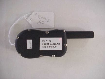
Click to zoom
Application Details
- Equipment Class
- DSC - Part 15 Security/Remote Control Transmitter
- Date of Grant
- Aug 08, 2006
- Application Purpose
- Original Equipment
- Date of Application
- Aug 07, 2006
- Equipment Note
- Hand Held Remote
- Frequency Range
- 303.82500000 - 303.82500000
- Company
- Radio Systems Corp
- Country
- United States
Documents & Files
Document Text
Text extracted from the exhibit documents filed with the FCC. Open a document above to read the original.
Users Manual
Please read this entire guide before beginning YardTrainer SD-105 Operating Guide FPO 2 1-800-732-0144 Thank you for choosing SportDOG Brand™. Used properly, this product will help you train your dog effi ciently and safely. To ensure your satisfaction, please review this owner’s manual thoroughly. If you have questions regarding this product’s operation, please see this manual’s Frequently Asked Questions or Troubleshooting section, contact our Customer Care Center at 1-800-732-0144, or visit our website at www.sportdogbrand.com. ____________________________________________________________________ Table of Contents Components ...............................................................................................3 How the System Works ................................................................................3 Key Defi nitions ...........................................................................................4 Prepare the Remote Transmitter ...................................................................5 Prepare the Collar Receiver..........................................................................6 Fit the Collar Receiver .................................................................................7 Find the Best Intensity Level for Your Dog ...................................................8 Reset the Collar Receiver ............................................................................9 Frequently Asked Questions ...................................................................... 10 Troubleshooting ........................................................................................ 11 Test Light Instructions .............................................................................. 12 Terms of Use and Limitation of Liability .................................................... 12 www.sportdogbrand.com 3 Components How the System Works The SportDOG YardTrainer SD-105 has been proven safe, comfortable and effective for all dogs over 8 pounds. Consistent, correct use of this product allows you to reinforce commands and correct misbehavior from up to 100 yards. The Remote Transmitter sends a signal, activating the Collar Receiver to deliver a harmless stimulation. With proper training, a dog will learn to associate this signal with a command. Like all SportDOG products, this model features adjustable stimulation levels so you can tailor the stimulation level to your dog’s temperament, eliminating the risk of over-correction. Important: The YardTrainer SD-105 has a range of up to 100 yards. Depending on the way you hold the Remote Transmitter, the maximum range may vary. For consistent results at longer ranges, hold the Remote Transmitter in a vertical position away from your body and over your head. Terrain, weather, vegetation, transmission from other radio devices, and other factors will affect the maximum range. 4 1-800-732-0144 Intensity Dial Key Defi nitions Remote Transmitter: Transmits the radio signal to the Collar Receiver. It is weatherproof and cannot be submerged in water. Intensity Dial: Provides multiple levels of stimulation so you can match the correction to your dog’s temperament. Transmitter Indicator Light: Indicates that a button is pressed and also serves as a low battery indicator. Upper Button: This button is factory-set to deliver Continuous Stimulation. Lower Button: This button is factory-set to deliver Continuous Stimulation two levels higher than the setting on the Intensity Dial. Side Button: This button is factory-set to deliver a tone without stimulation. Collar Receiver: Receives the radio signal from the Remote Transmitter. It is waterproof and can be submerged in water. Receiver Indicator Light: Indicates when the Collar Receiver has been turned on or off and also serves as a low battery indicator. Contact Points: The contacts through which the Collar Receiver delivers stimulation when the Remote Transmitter upper or lower button is pressed. On/Off Button: Momentarily pressing and holding this button turns the Collar Receiver on and off. Continuous Stimulation: You control both when and how long stimulation is delivered to your dog through the Collar Receiver’s Contact Points. When a Continuous Stimulation button is pressed for 8 seconds or more, the Remote Transmitter will “time-out.” The button will need to be released and pressed again before additional stimulation can be delivered. On/Off Button Contact Points Receiver Indicator Light Collar Receiver Remote Transmitter Transmitter Indicator Light Transmitter Antenna Upper Button Lower Button Side Button www.sportdogbrand.com 5 Prepare the Remote Transmitter Inserting 3-Volt Batteries 1. Remove the battery cover from the back of the Remote Transmitter by using a coin and turning it counter-clockwise. 2. Insert 3-volt batteries and secure the battery cover. Note: Approximate battery life will be 3 months, depending upon frequency of use. Transmitter Indicator Light Remote Transmitter FunctionIndicator Light Response Continuous Stimulation or Tone Only button pressed Solid in color Low battery – Continuous Stimulation or Tone Only button pressed Flashes continuously Step 1 6 1-800-732-0144 Prepare the Collar Receiver Inserting 3-Volt Batteries 1. Use a small Philips screwdriver to remove the two screws on the receiver. 2. Press the battery door up in the direction of the arrows on the door. It will move up slightly and the door will release. 3. Insert two, 3-volt lithium CR2032 batteries per the diagram on the receiver. 4. Replace the battery door. Check to ensure the gasket is in place and clean. 5. Tighten the screws. Do not over tighten. Press Door Up Pull Door Out Gasket To Turn the Collar Receiver On: 1. Press and hold the On/Off Button until the Receiver Indicator Light comes on and the Collar Receiver beeps 5 times. 2. Release the On/Off Button. The Receiver Indicator Light will fl ash until the Collar Receiver is turned off. The fl ashing light…
Text truncated - open the document above for the full version.
Block Diagram
SECTION 4 BLOCK DIAGRAM(S)/SCHEMATICS Manual Buttons Micro Battery RF Oscillator 303.825 Antenna BLOCK DIAGRAM
Cover Letter(s)
ATCB Mr. Tim Johnson RE: Radio Systems Corporation FCC ID: KE3-FT303 In response to your comments: After a review of the submitted information for FCC, I have a few comments on the above referenced Application. 1) Please provide operation description exhibit for this application. Uploaded. 2) Were various button/dial configurations investigated in effort to observe worse case duty cycle? If not, please evaluate and report worse case. Yes, various button/dial configurations were investigated in an effort to observe worst case duty cycle. Worst Case Duty Cycle was continuous transmission by holding the Shock and Tone Button of the transmitter. The dial was set at maximum shock value (8). 3) Schematics provided are not readable. Please provide higher resolution schematics. Uploaded in Word format for clarity and magnification. 4) TX shown in manual does not appear to match TX in this application. Please review/explain/correct as necessary. Manual will require complete review once corrected. A corrected manual has been uploaded. 4) Please explain 3 buttons and what each function does. Users manual only mentions 2 buttons. Corrected manual uploaded. Explanation located on page 4. 6) Test photos show device laying down with antenna in horizontal polarity but measurement antenna in vertical polarity. Photographs are expected to be taken to shown worse case configuration. However photographs suggest that the unit was not actually tested in all 3 axis as required by ANSI 63.4. Please confirm testing in all 3 axis or retest as appropriate. Unit was tested in all 3 axis configurations and worst case test data was provided. Photos were retaken after testing due to electronic photo problems. Test setup photos have been uploaded showing correct configuration, with unit vertical and antenna in vertical polarity. 7) Test configuration photographs must also be provided for AC powerline conducted emissions. Please provide. Uploaded 8) Please note column labeled AF+CA+Amp is not appropriate for conducted emissions. Generally this is an insertion loss and CA factor. The column is inherent in our calculation programs for both radiated and conducted emissions. The correction factors applied for Conducted Calculations are LISN and Cable loss only. 9) Please explain the limits 12,500 and 1,250 uV/m given for spurious emissions. This does not appear correct. Please review/explain/correct as necessary. Corrected and Uploaded. 10) Digital device emissions do not seem appropriate. It appears TX emissions appear in this section. Corrected and Uploaded 11) FYI....If RX is approved under a DoC, the manual provided does not appear to include required information for RX as given in 2.1077. Noted. 12) Our website shows an IC Number entered, but an ATCB IC form was not uploaded. Please clarify if you are requesting IC approval on this device as well, and if so please provide an appropriate form. See attachment provided. Please note that current uploads do not appear to show proper IC labeling as well. IC approval is requested. RSS-100 Form uploaded with revised label. Thank you for your comments. Sincerely, Louis A. Feudi V.P. Operations/Engineering
Cover Letter(s)
FCC ID: KE3-FT303 CONFIDENTIALITY REQUEST Date: January 16, 2006 Federal Communications Commission Equipment Authorizations Branch 7435 Oakland Mills Road Columbia, MD 21046 Gentlemen: Radio Systems Corporation respectfully requests confidentiality of certain materials provided with the submission of the FT-303 under FCC ID: KE3-FT303 in accordance with FCC Regulations 0.459. The confidentiality request applies to the schematic contained in Section 4. The FT-303 has been developed at considerable effort and expense by Radio Systems Corporation. These items are considered as Trade Secrets and therefore public access to the proprietary material could possibly result in duplication of equipment that could severely damage the company's business advantage. I appreciate your assistance in the matter: Sincerely, Name: __Louis A. Feudi_______Signature: ________________________ Title: _VP / Operations & EngineeringDate: ___January 16, 2006___________ 3505 Francis Circle Alpharetta, GA 30004 PH: 770-740-0717 Fax: 770-740-1508 www.ustech-lab.com
External Photos
SECTION 5 PHOTOGRAPHS PHOTOS OF THE TESTED EUT The following photos are attached: Photo 1. EUT, Front View Photo 2. EUT, Rear View Photo 1. EUT, Front View . Photo 2. EUT, Rear View .
ID Label/Location Info
THIS DEVICE COMPLIES WITH PART 15 OF THE FCC RULES. OPERATION IS SUBJECT TO THE FOLLOWING TWO CONDITIONS. (1) THIS DEVICE MAY NOT CAUSE HARMFUL INTERFERENCE, AND (2) THIS DEVICE MUST ACCEPT ANY INTERFERENCE RECEIVED, INCLUDING INTERFERENCE THAT MAY CAUSE UNDESIRED OPERATION. FCC ID: KE3-FT303 IC: 2721A-FT303 Project: FT-303 Description: LABEL FCC FT-303 RSC Part: 402-1566 Revision: 0 RSC Filename: 402-1566 Adobe Illustrator Version CS Date: 01-10-06 Drawn By: K Wiggins Approval: Material: 0.008” Rigid white vinyl, 0.001” polyester Color: Print text PMS Process White on PMS Process Black Background. TM World Leader In E-Training P E T T R A I N I N G S Y S T E M S ® 10427 Electric Ave. • Knoxville, TN 37932 FAX: 865.777.5415 • 865.777.5404 TM NOTES: 1. Print text as shown. 2. Units are in inches. 3. Tolerance: +/-0.005 4. Scale is 1:1
Internal Photos
SECTION 5 PHOTOGRAPHS PHOTOS OF THE TESTED EUT The following photos are attached: Photo 3. EUT, Cover Removed Photo 4. PCB Board Component Side Photo 5. PCB Board Solder Side Photo 6. Battery Photo 3. EUT Cover Removed. Photo 4. PCB Board Component Side Photo 5. PCB Board Solder Side Photo 6. Battery
Operational Description
FCC ID: KE3-FT303 U.S. Technologies, Inc. Test Report, Part 15 Rev: 040103 Report Number:05-0300Issue Date: January 17, 2006 Customer: Radio Systems Corporation Model: FT-303 OPERATIONAL DESCRIPTION Model FT-303 is a Pet Training System. The system transmits a 303.825 MHz continuous transmit signal for a maximum of 10 seconds, if the button is held. The receiver collar, on the pet, receives the signal generated by the transmitter. The collar receives signals at 303.825 MHz. When the signal is received, the collar generates a discouragement pulse to the pet. Maximum duty cycle is 6.630 msec every 69.75 msec. EUT ceases transmission 153 ms after release of button.
Test Report
Radio Systems Corporation FCC Part 15, Certification Application Model FT-303 Original Issue Date: January 17, 2006 3505 Francis Circle Alpharetta, GA 30004 PH: 770-740-0717 Fax: 770-740-1508 www.ustech-lab.com FCC ID: KE3-FT303 MEASUREMENT/TECHNICAL REPORT COMPANY NAME:Radio Systems Corporation MODEL:FT-303 FCC ID:KE3-FT303 ORIGINAL ISSUE DATE:January 17, 2006 This report concerns (check one): Original grant X Class II change_____ Equipment type: Low Power Transmitter Deferred grant requested per 47 CFR 0.457(d)(1)(ii)? yes_____ No X If yes, defer until:_________________ date N.A. agrees to notify the Commission by N.A. date of the intended date of announcement of the product so that the grant can be issued on that date. Report prepared by: United States Technologies, Inc. 3505 Francis Circle Alpharetta, GA 30004 Phone Number: (770) 740-0717 Fax Number: (770) 740-1508 FCC ID: KE3-FT303 TABLE OF CONTENTS AGENCY AGREEMENT LETTER OF CONFIDENTIALITY SECTION 1 GENERAL INFORMATION Product Description SECTION 2 TESTS AND MEASUREMENTS Configuration of Tested Test Facility Test Equipment Modifications Periodic Operation Field Strength of Fundamental Emission Field Strength of Spurious Emissions 20 dB Bandwidth of Fundamental Emission Frequency Tolerance of Carrier Signal Radiated Digital Device Emissions Power Line Conducted Emissions SECTION 3 LABELING INFORMATION SECTION 4 BLOCK DIAGRAM(S)/SCHEMATICS SECTION 5 PHOTOGRAPHS SECTION 6 USER'S MANUAL AMENDMENT ANNEX FCC ID: KE3-FT303 LIST OF FIGURES AND TABLES FIGURES Test Configuration Photograph(s) for Spurious and Fundamental Emissions Field Strength of Fundamental Emission Field Strength of Spurious Emissions Bandwidth of Fundamental Emission TABLES EUT and Peripherals Test Instruments Field Strength of Fundamental Emission Field Strength of Spurious Emissions Bandwidth of Fundamental Emission Radiated Emissions Power Line Conducted Emissions FCC ID: KE3-FT303 SECTION 1 GENERAL INFORMATION FCC ID: KE3-FT303 GENERAL INFORMATION Product Description The Equipment Under Test (EUT) is a Radio Systems Corporation 303.825 MHz Remote Transmitter Models FT-303, which sends a transmitted signal when one of three buttons is pressed. Related Submittal(s)/Grant(s) The EUT will be used with DoC approved receivers. FCC ID: KE3-FT303 SECTION 2 TESTS AND MEASUREMENTS FCC ID: KE3-FT303 TESTS AND MEASUREMENTS Configuration of Tested System The sample was tested per ANSI C63.4, Methods of Measurement from Low-Voltage Electrical and Electronic Equipment in the Range of 9 kHz to 40 GHz (1992). Conducted and radiated emissions data were taken with the test receiver or spectrum analyzer's resolution bandwidth adjusted to 9 kHz and 120 kHz, respectively. All measurements are peak unless stated otherwise. The video filter associated with the spectrum analyzer was off throughout the evaluation process. Interconnecting cables were manipulated as necessary to maximize emissions. A block diagram of the tested system is shown in Figure 1. Test configuration photographs for spurious and fundamental emissions are shown in Figure 2. Since the EUT is a hand held device, it was rotated about all 3 axis in order to obtain worse case results. Test Facility Testing was performed at US Tech's measurement facility at 3505 Francis Circle, Alpharetta, GA. This site has been fully described and submitted to the FCC, and accepted in their letter marked 31040/SIT. Additionally this site has also been fully described and submitted to Industry Canada (IC), and has been approved under file number IC2982. Modifications 1) No modifications were necessary to bring the EUT into compliance with the Part 15.231 limits Test Equipment Table 2 describes test equipment used to evaluate this product. FCC ID: KE3-FT303 FIGURE 1 TEST CONFIGURATION Transmitter (EUT) FCC ID: KE3-FT303 FIGURE 2a Photographs for Spurious and Fundamental Emissions FCC ID: KE3-FT303 FIGURE 2b Photograph(s) for Spurious and Fundamental Emissions FCC ID: KE3-FT303 TABLE 1 EUT and Peripherals PERIPHERAL MANUFACTURER MODEL NUMBER SERIAL NUMBER FCC ID:CABLES P/D Remote Transmitter Radio Systems Corporation (EUT) FT-303NoneKE3-FT303None FCC ID: KE3-FT303 TABLE 2 TEST INSTRUMENTS EQUIPMENTMODEL NUMBER MANUFACTURERSERIAL NUMBER DATE OF LAST CALIBRATION SPECTRUM ANALYZER8593EHEWLETT-PACKARD3205A001247/5/05 RF PREAMP8447DHEWLETT-PACKARD2944A07436Daily Calibration RF PREAMP8449BHEWLETT-PACKARD3008A004806/30/05 HORN ANTENNASAS-571A.H. Systems6054/1/05 LOG PERIODIC ANTENNA3136EMCO9110-32369/19/05 CALCULATION PROGRAMN/A N/AVer. 5.2N/A FCC ID: KE3-FT303 Periodic Operation (47 CFR 15.231(a1)) A transmitter manually activated must automatically deactivate within not more than 5 seconds of being released. The transmitter is a 3 button transmitter. The EUT continues to transmit while each button is being pressed. The EUT ceases transmission within 300 msec upon being released as shown in Figure 3. FCC ID: KE3-FT303 FIGURE 3 Periodic Operation 15.231(a)(c1) FCC ID: KE3-FT303 Field Strength of Fundamental Emission (47 CFR 15.231b) Measurements were made using a peak detector. Field strength of the peak fundamental emission is shown in Table 3a and Figure 4. Duty Cycle Correction During 100 msec: For detailed information regarding the duty cycle, please see Figures 5a through 5e. Bit sequence contains 3 sync pulses (1.0200 msec) and 7 pulse position encoded data bits (0.510 msec). The 7 data bits consists of 4 ID bits, 1 Function Bit, and 2 shock level bits. Total TX = (3 * 1.0200) + (7 * 0.510) = 6.630 msec every 69.75 msec Duty Cycle = 6.62791/66.750 = 9.50% Duty Cycle Correction = 20 log (0.09505) = -20.44 dB Field strength of the average fundamental emission is shown in Table 3b. FCC ID: KE3-FT303 TABLE 3a FIELD STRENGTH OF FUNDAMENTAL EMISSION Test Date:December 4, 2005 UST Project:05-0300 Customer:Radio Systems Corporation Model:FT-303 Peak Measurement FREQ. (MHz) TEST DATA (dBm) @ 3m ANTENNA FACTOR + CABLE ATTENUATION RESULTS (uV/m) @ 3m PEAK…
Text truncated - open the document above for the full version.
Test Setup Photos
FIGURE 2a Photographs for Spurious and Fundamental Emissions FIGURE 2b Photograph(s) for Spurious and Fundamental Emissions FIGURE 2c Photograph(s) for Conducted Emissions
Contact Information
Applicant
Deborah J. LeMaster(Regulatory Compliance Specialist)
Technical Contact
U.S. TechnologiesLou Feudi
[email protected]7707400717
3505 Francis Circle · Alpharetta, Georgia · United States
Test Firm
US TechGeorge Yang
Technical Specifications
| # | Rule Parts | Frequency Range | Power Output |
|---|---|---|---|
| 1 | 15.231 | 303.825 MHz - 303.825 MHz | - |
Other Applications from Radio Systems Corp

KE3-PIF150-2
Jun 18, 2026Stay & Play Wireless Fence
Equipment Class
DCD - Part 15 Low Power Transmitter Below 1705 kHz
KE3-3003841
Jun 05, 2026PetSafe HydroSphere 60 oz Cordless Fountain
Equipment Class
FDS - Part 15 Field Disturbance Sensor
KE3-3003832
Apr 08, 2026GPS Tracker Collar
Equipment Class
DTS - Digital Transmission System
KE3-3003791
Jul 01, 2024MURS radio device
Equipment Class
TNB - Licensed Non-Broadcast Station Transmitter
KE3-3003803
Apr 06, 2024Dog Training Collar
Equipment Class
DSC - Part 15 Security/Remote Control Transmitter