KE3-FT303APet Training System Transmitter
Radio Systems Corp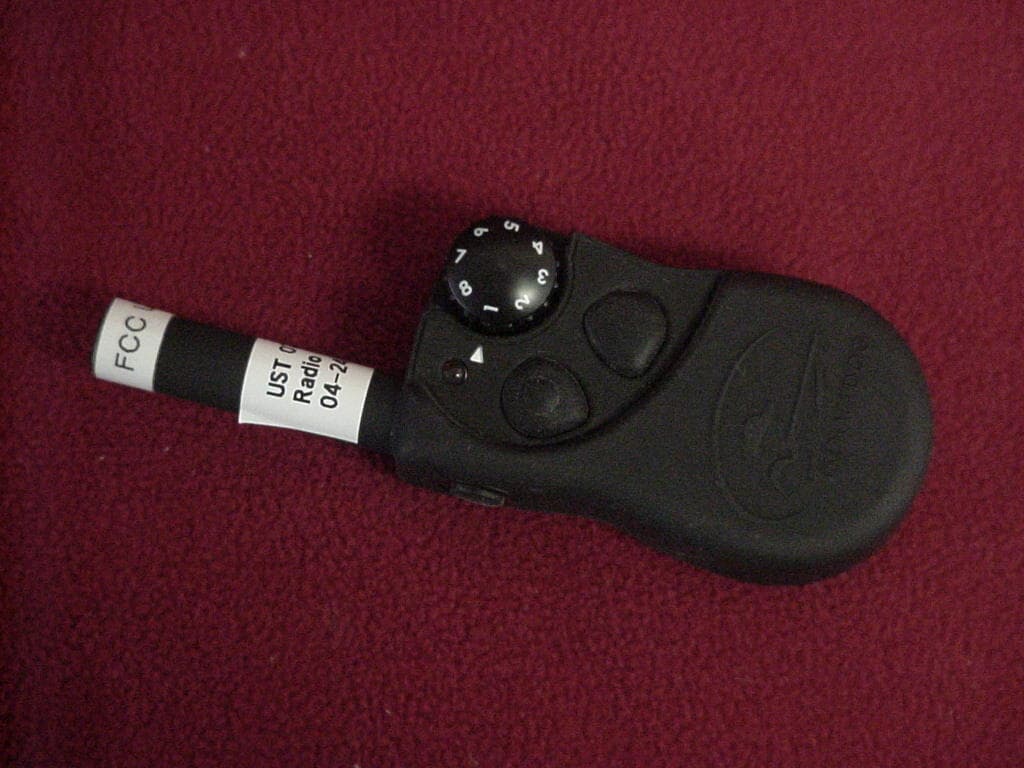
Click to zoom
Application Details
- Equipment Class
- DSC - Part 15 Security/Remote Control Transmitter
- Date of Grant
- Oct 03, 2007
- Application Purpose
- Original Equipment
- Date of Application
- Oct 01, 2007
- Equipment Note
- Pet Training System Transmitter
- Frequency Range
- 303.82500000 - 303.82500000
- Company
- Radio Systems Corp
- Country
- United States
Documents & Files
Document Text
Text extracted from the exhibit documents filed with the FCC. Open a document above to read the original.
Users Manual
Please read this entire guide before beginning YardTrainer SD-105 Operating Guide FPO 2 1-800-732-0144 Thank you for choosing SportDOG Brand™. Used properly, this product will help you train your dog effi ciently and safely. To ensure your satisfaction, please review this owner’s manual thoroughly. If you have questions regarding this product’s operation, please see this manual’s Frequently Asked Questions or Troubleshooting section, contact our Customer Care Center at 1-800-732-0144, or visit our website at www.sportdogbrand.com. ____________________________________________________________________ Table of Contents Components ...............................................................................................3 How the System Works ................................................................................3 Key Defi nitions ...........................................................................................4 Prepare the Remote Transmitter ...................................................................5 Prepare the Collar Receiver..........................................................................6 Fit the Collar Receiver .................................................................................7 Find the Best Intensity Level for Your Dog ...................................................8 Reset the Collar Receiver ............................................................................9 Frequently Asked Questions ...................................................................... 10 Troubleshooting ........................................................................................ 11 Test Light Instructions .............................................................................. 12 Terms of Use and Limitation of Liability .................................................... 12 www.sportdogbrand.com 3 Components How the System Works The SportDOG YardTrainer SD-105 has been proven safe, comfortable and effective for all dogs over 8 pounds. Consistent, correct use of this product allows you to reinforce commands and correct misbehavior from up to 100 yards. The Remote Transmitter sends a signal, activating the Collar Receiver to deliver a harmless stimulation. With proper training, a dog will learn to associate this signal with a command. Like all SportDOG products, this model features adjustable stimulation levels so you can tailor the stimulation level to your dog’s temperament, eliminating the risk of over-correction. Important: The YardTrainer SD-105 has a range of up to 100 yards. Depending on the way you hold the Remote Transmitter, the maximum range may vary. For consistent results at longer ranges, hold the Remote Transmitter in a vertical position away from your body and over your head. Terrain, weather, vegetation, transmission from other radio devices, and other factors will affect the maximum range. 4 1-800-732-0144 Intensity Dial Key Defi nitions Remote Transmitter: Transmits the radio signal to the Collar Receiver. It is weatherproof and cannot be submerged in water. Intensity Dial: Provides multiple levels of stimulation so you can match the correction to your dog’s temperament. Transmitter Indicator Light: Indicates that a button is pressed and also serves as a low battery indicator. Upper Button: This button is factory-set to deliver Continuous Stimulation. Lower Button: This button is factory-set to deliver Continuous Stimulation two levels higher than the setting on the Intensity Dial. Side Button: This button is factory-set to deliver a tone without stimulation. Collar Receiver: Receives the radio signal from the Remote Transmitter. It is waterproof and can be submerged in water. Receiver Indicator Light: Indicates when the Collar Receiver has been turned on or off and also serves as a low battery indicator. Contact Points: The contacts through which the Collar Receiver delivers stimulation when the Remote Transmitter upper or lower button is pressed. On/Off Button: Momentarily pressing and holding this button turns the Collar Receiver on and off. Continuous Stimulation: You control both when and how long stimulation is delivered to your dog through the Collar Receiver’s Contact Points. When a Continuous Stimulation button is pressed for 8 seconds or more, the Remote Transmitter will “time-out.” The button will need to be released and pressed again before additional stimulation can be delivered. On/Off Button Contact Points Receiver Indicator Light Collar Receiver Remote Transmitter Transmitter Indicator Light Transmitter Antenna Upper Button Lower Button Side Button www.sportdogbrand.com 5 Prepare the Remote Transmitter Inserting 3-Volt Batteries 1. Remove the battery cover from the back of the Remote Transmitter by using a coin and turning it counter-clockwise. 2. Insert 3-volt batteries and secure the battery cover. Note: Approximate battery life will be 3 months, depending upon frequency of use. Transmitter Indicator Light Remote Transmitter FunctionIndicator Light Response Continuous Stimulation or Tone Only button pressed Solid in color Low battery – Continuous Stimulation or Tone Only button pressed Flashes continuously Step 1 6 1-800-732-0144 Prepare the Collar Receiver Inserting 3-Volt Batteries 1. Use a small Philips screwdriver to remove the two screws on the receiver. 2. Press the battery door up in the direction of the arrows on the door. It will move up slightly and the door will release. 3. Insert two, 3-volt lithium CR2032 batteries per the diagram on the receiver. 4. Replace the battery door. Check to ensure the gasket is in place and clean. 5. Tighten the screws. Do not over tighten. Press Door Up Pull Door Out Gasket To Turn the Collar Receiver On: 1. Press and hold the On/Off Button until the Receiver Indicator Light comes on and the Collar Receiver beeps 5 times. 2. Release the On/Off Button. The Receiver Indicator Light will fl ash until the Collar Receiver is turned off. The fl ashing light…
Text truncated - open the document above for the full version.
Cover Letter(s)
Confidentiality Request 5/30/07 AmericanTCB 6731 Whittier Ave McLean, VA 22101 FCC ID: KE3-FT-303A In regard to the exhibits submitted in support of the application for FCC ID: KE3-FT303A, please classify the following as confidential under the provision of 47 CFR 0.459: • Schematics • Block Diagram These exhibits contain technical information which Radio Systems deems to be sensitive and proprietary. Therefore this information cannot be published. If this information were to be made public it could be used to the disadvantage of the applicant in the marketplace. Louis A. Feudi VP Operations and Engineering US Technologies (US Tech Authorized Agent for Radio Systems) 3505 Francis Circle Alpharetta, GA 30004 PH: 770-740-0717 Fax: 770-740-1508 www.ustech-lab.com
Cover Letter(s)
3505 Francis Circle Alpharetta, GA 30004 PH: 770-740-0717 Fax: 770-740-1508 www.ustech-lab.com September 28, 2007 ATCB Mr. Richard Fabina RE: ATCB005022 for Radio Systems Corporation FCC ID: KE3-FT303A Mr. Fabina: The following is my response to your letter with comments regarding the above submittal. I have included your original text to respond to. I have a few comments on this Application. Depending on your responses, kindly understand there may be additional comments. 1. Please confirm that this transmitter is not a learned mode transmitter where it determines its pulse train from a device that is operated by the consumer. Learned mode transmitters cannot be approved by America TCB. The Transmitter is not a learned mode transmitter. 2. The FCC ID label is wrong. It is missing the term “FCC ID” (See Section 2.925(a)(1) of the FCC Rules. This section reads “FCC Identifier consisting of the two elements in the exact order specified in §2.926. The FCC Identifier shall be preceded by the term FCC ID in capital letters on a single line, and shall be of a type size large enough to be legible without the aid of magnification.” Please revise the label exhibit accordingly. Revised and Uploaded 3. Please confirm that all buttons were depressed to determine worst case duty cycle factor and all buttons either transmit the same pulse train or the worst case was chosen for determining the duty cycle correction factor. Plot 5d shows 20 pulses in the pulse train while plots 5c and 5e show either 31 or 33 pulses in the pulse train. If the duty cycle increases, recalculate the duty cycle correction factor using item 7 below. Plots 5a and 5b show transmit time of the 2 discrete pulse types used in the transmission. Plot 5d shows a single cycle of the pulse train. This cycle is repeated 4 times every 380.63 ms as shown in plot 5e. Original duty cycle correction was conducted as 26.4 ms every 380.63 ms as that was the duty cycle, yielding -23.18 dB duty cycle correction factor. However, since the maximum allowed time to determine duty cycle correction is every 100 ms, and assuming that all pulse transmissions occur in the 100 ms time period, the duty cycle factor becomes: 20 log (26.4/100) = -11.6 dB Correction Factor (as calculated below under item 7) The report has been corrected accordingly and uploaded. 3505 Francis Circle Alpharetta, GA 30004 PH: 770-740-0717 Fax: 770-740-1508 www.ustech-lab.com 4. Please confirm that all buttons were depressed to determine worst case radiated emissions from this transmitter and what mode or button represents the worst case radiated data submitted. If the duty cycle increases, recalculate the duty cycle correction factor using item 7 below. This confirms that all buttons were depressed to determine the worst case radiated emissions. The side transmit button represents the worst case radiated emission. The EUT was also tested in all three axis to determine worst case emission. 5. Please confirm that the knob that increases the intensity of the pet training signal does not increase the duty cycle correction factor by increasing the number or width of pulses sent in a pulse train. If the duty cycle increases, recalculate the duty cycle correction factor using item 7 below. This is confirmation that the knob increases the voltage applied but does not increase the duty cycle. 6. The letter granting US Tech the authority to act as your agent before the FCC comes from a different company (Pet Safe Training Systems) than Radio Systems Corporation. Please either provide another letter from Radio Systems authorizing US Tech authority to act as your agent or give Pet Safe the authority to do so. There must be traceability back to the applicant, Radio Systems Corporation on all actions in this application. Pet Safe Training Systems is the Copyrighted Trademark of Radio Systems Inc. This Agency letter has been used since 2005 to allow us to act as agent for Radio Systems. All prior applications that have been granted by ATCB for Radio Systems has used this letter. Can it continue to be accepted? 7. For your information – The duty cycle correction factor was calculated incorrectly. Duty factors are calculated over the entire pulse train including blanking intervals or 100 milliseconds whichever is shorter. In this case, the pulse train exceeds 100 mS. Therefore, you must choose the maximum on time for the pulse train during any 100 mS window. See ANSI C63.4(2003), Annex H4, step J and Section 15.35(c) of the FCC Rules for help. If the answers to issue 3 above do not change what has been represented in this filing, I have calculated the worst case duty factor as being -11.6 dB if all pulse transmissions occur within the 100 mS window (which they will not). But even using this duty cycle correction factor, the transmitter complies with all the requirements for field strength of fundamental, spurious and restricted band radiated emissions. Please make a note of this requirement for future applications. Noted. See item 3 above. Report corrected and uploaded. Thank you for your attention to this matter. Please contact me with any further questions. Sincerely, Louis A. Feudi Vice President of Operations and Engineering
External Photos
SECTION 5 PHOTOGRAPHS PHOTOS OF THE TESTED EUT The following photos are attached: Photo 1. EUT, Front View Photo 2. EUT, Rear View Photo 1. EUT, Front View . Photo 2. EUT, Rear View .
ID Label/Location Info
Project: FT-303 Description: Artwork, Model Number RSC Part: 417-066 Revision: 3; 03/28/07 RSC Filename: 417-066 Adobe Illustrator Version CS Date: 06-15-06 Drawn By: K.Wiggins Approval: Material: Silkscreen Color: Pantone Process White TM World Leader In E-Training P E T T R A I N I N G S Y S T E M S ® 10427 Electric Ave. • Knoxville, TN 37932 FAX: 865.777.5415 • 865.777.5404 TM 1. Print text as oriented 2. Scale is 1 to 1 700-780 FT-303 SWR/1 FCC ID:KE3-FT303A SD-105/S
Internal Photos
SECTION 5 PHOTOGRAPHS PHOTOS OF THE TESTED EUT The following photos are attached: Photo 3. EUT, Cover Removed Photo 4. PCB Board Component Side Photo 5. PCB Board Solder Side Photo 3. EUT Cover Removed. Photo 4. PCB Board Component Side Photo 5. PCB Board Solder Side
Operational Description
FCC ID: KE3-FT303A U.S. Technologies, Inc. Report Number: 07-0085 Customer: Radio Systems Corporation Model: FT-303A OPERATIONAL DESCRIPTION Model FT-303A is a Pet Training System. The system transmits a 303.825 MHz continuous transmit signal for a maximum of 10 seconds, if the button is held. The receiver collar, on the pet, receives the signal generated by the transmitter. The collar receives signals at 303.825 MHz. When the signal is received, the collar generates a discouragement pulse to the pet.
Test Report
Page 1 of 42 Radio Systems Corporation FCC Part 15, Certification Application Model FT-303A Original Issue Date: May 25, 2007 3505 Francis Circle Alpharetta, GA 30004 PH: 770-740-0717 Fax: 770-740-1508 www.ustech-lab.com FCC ID: KE3-FT303A Page 2 of 42 MEASUREMENT/TECHNICAL REPORT COMPANY NAME: Radio Systems Corporation MODEL: FT-303A FCC ID: KE3-FT303A ORIGINAL ISSUE DATE: May 25, 2007 This report concerns (check one): Original grant X Class II change_____ Equipment type: Low Power Transmitter Deferred grant requested per 47 CFR 0.457(d)(1)(ii)? yes_____ No X If yes, defer until:_________________ date N.A. agrees to notify the Commission by N.A. date of the intended date of announcement of the product so that the grant can be issued on that date. Report prepared by: United States Technologies, Inc. 3505 Francis Circle Alpharetta, GA 30004 Phone Number: (770) 740-0717 Fax Number: (770) 740-1508 FCC ID: KE3-FT303A Page 3 of 42 TABLE OF CONTENTS AGENCY AGREEMENT LETTER OF CONFIDENTIALITY SECTION 1 GENERAL INFORMATION Product Description SECTION 2 TESTS AND MEASUREMENTS Configuration of Tested EUT Test Facility Test Equipment Modifications Periodic Operation Field Strength of Fundamental Emission Field Strength of Spurious Emissions 20 dB Bandwidth of Fundamental Emission Frequency Tolerance of Carrier Signal Radiated Digital Device Emissions Power Line Conducted Emissions SECTION 3 LABELING INFORMATION SECTION 4 BLOCK DIAGRAM(S)/SCHEMATICS SECTION 5 PHOTOGRAPHS SECTION 6 USER'S MANUAL FCC ID: KE3-FT303A Page 4 of 42 LIST OF FIGURES AND TABLES FIGURES Test Configuration Photograph(s) for Spurious and Fundamental Emissions Field Strength of Fundamental Emission Field Strength of Spurious Emissions Bandwidth of Fundamental Emission TABLES EUT and Peripherals Test Instruments Field Strength of Fundamental Emission Field Strength of Spurious Emissions Bandwidth of Fundamental Emission Radiated Emissions Power Line Conducted Emissions FCC ID: KE3-FT303A Page 5 of 42 SECTION 1 GENERAL INFORMATION FCC ID: KE3-FT303A Page 6 of 42 GENERAL INFORMATION Product Description The Equipment Under Test (EUT) is a Radio Systems Corporation 303.91 MHz Remote Transmitter Model FT-303A, which sends a transmitted signal when one of three buttons is pressed. Related Submittal(s)/Grant(s) The EUT will be used with DoC approved receivers. FCC ID: KE3-FT303A Page 7 of 42 SECTION 2 TESTS AND MEASUREMENTS FCC ID: KE3-FT303A Page 8 of 42 TESTS AND MEASUREMENTS Configuration of Tested System The sample was tested per ANSI C63.4, Methods of Measurement from Low-Voltage Electrical and Electronic Equipment in the Range of 9 kHz to 40 GHz (2003). Conducted and radiated emissions data were taken with the test receiver or spectrum analyzer's resolution bandwidth adjusted to 9 kHz and 120 kHz, respectively. All measurements are peak unless stated otherwise. The video filter associated with the spectrum analyzer was off throughout the evaluation process. Interconnecting cables were manipulated as necessary to maximize emissions. A block diagram of the tested system is shown in Figure 1. Test configuration photographs for spurious and fundamental emissions are shown in Figure 2. Since the EUT is a hand held device, it was rotated about all 3 axis in order to obtain worst case results. Test Facility Testing was performed at US Tech's measurement facility at 3505 Francis Circle, Alpharetta, GA. This site has been fully described and registered with the FCC, under designation number US5117. Additionally this site has also been fully described and submitted to Industry Canada (IC), and has been approved under file number IC2982. Modifications 1) No modifications were necessary to bring the EUT into compliance with the Part 15.231 limits Test Equipment Table 2 describes test equipment used to evaluate this product. FCC ID: KE3-FT303A Page 9 of 42 FIGURE 1 TEST CONFIGURATION Transmitter (EUT) FCC ID: KE3-FT303A Page 10 of 42 FIGURE 2a Photographs for Spurious and Fundamental Emissions FCC ID: KE3-FT303A Page 11 of 42 FIGURE 2b Photograph(s) for Spurious and Fundamental Emissions FCC ID: KE3-FT303A Page 12 of 42 TABLE 1 EUT and Peripherals PERIPHERAL MANUFACTURER MODEL NUMBER SERIAL NUMBER FCC ID: CABLES P/D Remote Transmitter Radio Systems Corporation (EUT) FT-303A None KE3-FT303A None FCC ID: KE3-FT303A Page 13 of 42 TABLE 2 TEST INSTRUMENTS EQUIPMENT MODEL NUMBER MANUFACTURER SERIAL NUMBER DATE OF LAST CALIBRATION SPECTRUM ANALYZER 8593E HEWLETT-PACKARD 3205A00124 7/3/06 RF PREAMP 8447D HEWLETT-PACKARD 2944A07436 5/24/06 RF PREAMP 8449B HEWLETT-PACKARD 3008A00480 8/10/06 HORN ANTENNA 3115 A.H. Systems 9107-3723 10/16/06 2 Year LOG PERIODIC ANTENNA 3136 EMCO 9110-3236 9/15/05 2 Year CALCULATION PROGRAM N/A N/A Ver. 6.0 N/A FCC ID: KE3-FT303A Page 14 of 42 Periodic Operation (47 CFR 15.231(a1)) A transmitter manually activated must automatically deactivate within not more than 5 seconds of being released. The transmitter is a 3 button transmitter. The EUT continues to transmit while each button is being pressed. The EUT ceases transmission within 300 msec upon being released as shown in Figure 3. FCC ID: KE3-FT303A Page 15 of 42 FIGURE 3 Periodic Operation 15.231(a)(c1) FCC ID: KE3-FT303A Page 16 of 42 Field Strength of Fundamental Emission (47 CFR 15.231b) Measurements were made using a peak detector. Field strength of the peak fundamental emission is shown in Table 3a and Figure 4. Duty Cycle Correction During 100 msec: For detailed information regarding the duty cycle, please see Figures 5a through 5e. Plots 5a and 5b show transmit time of the 2 discrete pulse types used in the transmission. Plot 5d shows a single cycle of the pulse train. This cycle is repeated 4 times every 380.63 ms as shown in plot 5e. Bit sequence contains 3 sync pulses (0.975 msec) and 7 pulse position encoded data bits (0.525 msec). The 7 data bits consists of 4 ID bits, 1 Function Bit, and 2 shock level bits. Total TX = 4 * {(3 * 0.975) + (7 * 0.525)} = 26.…
Text truncated - open the document above for the full version.
Test Setup Photos
FIGURE 2a Photographs for Spurious and Fundamental Emissions FIGURE 2b Photograph(s) for Spurious and Fundamental Emissions
Contact Information
Applicant
Deborah J. LeMaster(Regulatory Compliance Specialist)
Technical Contact
US TechLou Feudi
[email protected]770-740-0717
3505 Francis Circle · Alpharetta, Georgia · United States
Test Firm
US TechGeorge Yang
Technical Specifications
| # | Rule Parts | Frequency Range | Power Output |
|---|---|---|---|
| 1 | 15.231 | 303.825 MHz - 303.825 MHz | - |
Other Applications from Radio Systems Corp

KE3-PIF150-2
Jun 18, 2026Stay & Play Wireless Fence
Equipment Class
DCD - Part 15 Low Power Transmitter Below 1705 kHz
KE3-3003841
Jun 05, 2026PetSafe HydroSphere 60 oz Cordless Fountain
Equipment Class
FDS - Part 15 Field Disturbance Sensor
KE3-3003832
Apr 08, 2026GPS Tracker Collar
Equipment Class
DTS - Digital Transmission System
KE3-3003791
Jul 01, 2024MURS radio device
Equipment Class
TNB - Licensed Non-Broadcast Station Transmitter
KE3-3003803
Apr 06, 2024Dog Training Collar
Equipment Class
DSC - Part 15 Security/Remote Control Transmitter