KE3-PROTX1PLUSpet containment system
Radio Systems Corp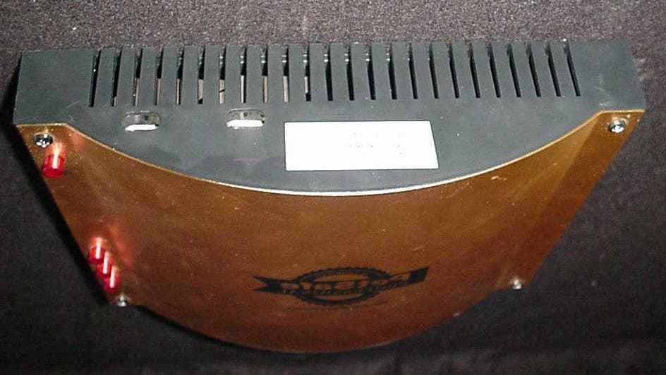
Click to zoom
Application Details
- Equipment Class
- DCD - Part 15 Low Power Transmitter Below 1705 kHz
- Date of Grant
- Jun 14, 2006
- Application Purpose
- Original Equipment
- Date of Application
- Jun 14, 2006
- Equipment Note
- pet containment system
- Frequency Range
- 0.01065000 - 0.01065000
- Company
- Radio Systems Corp
- Country
- United States
Documents & Files
Document Text
Text extracted from the exhibit documents filed with the FCC. Open a document above to read the original.
Users Manual
Congratulations! You have chosen the World’s best selling pet containment system. Our mission is to ensure your pet’s safety by providing you the tools and techniques to successfully train your pet. If this is your fi rst pet containment system, there are just a few important things you need to know: • Use the system with healthy pets only. • This system may not be effective for vicious or aggressive pets. If your pet poses a threat to others, DO NOT USE THE SYSTEM. • The system is for residential use only. • You can contain several pets within the Pet Area, but each one must wear a Receiver Collar. Setup and Ongoing Operation Your PetSafe Professional will perform all the setup steps for you. 1. Bury the Wire at the Boundary you specify. 2. Install the Transmitter in a dry location. 3. Install the batteries in the Receiver Collar and Remote Transmitter. 4. Set the Correction Level and test the Receiver Collar. 5. Place the Receiver Collar on your pet. For the system to operate properly, you must fi rst • Train your pet to the containment system. (See the training plan enclosed.) After you’ve completed training, you can begin using the Remote Transmitter portion of the ProTx ® -Plus System. (See Training Guide enclosed) • Regularly check and clean your pet’s neck. If the Receiver Collar is too tight or your pet wears it too long, it can cause Pressure Necrosis, a condition where the skin deteriorates. If a rash or sore forms, remove the Receiver Collar for a few days. When replacing the Receiver Collar, make sure the Contact Posts and the pet’s neck are clean. Consult a veterinarian if needed. • Every month, check that the Receiver Collar beeps near the Boundary. If not, check the Troubleshooting Guide. • Battery life depends upon how often your pet tests the Boundary. The SafeLight™ acts as a low battery indicator, fl ashing every 4 to 5 seconds when replacement is required. • Always be careful when using a weed eater or shovel near the Boundary to prevent damage to the Wire. ProTx ® Plus Transmitter The Transmitter is the control center for the fence. It plugs into a standard outlet. It is not waterproof and must be installed in a dry location. Ask your PetSafe Professional about our Gentle LiteTouch Training ™ video and other options. ProLite ® Receiver Collar When your pet reaches the Warning Zone, the Receiver Collar gives a warning beep. If your pet continues into the Static Correction Zone, a safe Static Correction will be delivered through the Contact Posts to get his attention until he returns to the Pet Area. Waterproof Case SafeLight™— LED indicator of low battery and Correction Level Battery Door Contact Posts deliver the Static Correction—2 sizes, short (for most pets) and long (for pets with long hair) Magnet Key Dot— adjusts the Correction Level P O W E R L O O P 1 Power On/Off Light Receiver Collar Test Light Light on: no Wire problems Light off: possible broken Wire Boundary Loop 1 Light Test Station— Place Receiver Collar Contact Posts Here PRO GRA M + Remote Transmitter Transmitter Indicator Light Stimulation and Tone Button Tone Only Button Programming Button Correction Level Magnet Operating Guide Prepare the Remote Transmitter To Insert and Remove the Battery 1. Hold the Remote Transmitter face down and pull the battery door open (A). 2. Insert the 9-volt battery with the positive side oriented as shown (B). 3. Replace the battery door by positioning the bottom edge (C), and snap the battery door into place. To verify the battery has been inserted correctly 1. Press either button on the Remote Transmitter. 2. The Transmitter Indicator Light should come on. 3. If the Transmitter Indicator Light does not come on, you may have inserted a bad or dead battery. Try taking it out and replacing it with one that is known to be good. 4. If the Transmitter Indicator Light still does not come on, contact your PetSafe Professional. Prepare the Receiver Collar To Insert and Remove the Batteries 1. With a coin, unlock the Battery Door and remove it (D). 2. Insert two 3-volt Lithium (CR2032 batteries) into the Battery Door (D). 3. Place the Battery Door back into the Receiver (E). 4. With a coin, slide Battery Door latch to lock it (E). To Pair the Remote Transmitter and the ProTx ® -Plus Transmitter If your Receiver Collar does not beep when the Tone Only Button of the Remote Transmitter is pressed, or if you feel the Receiver Collar is not responding: 1. With the Receiver Collar off your pet, Separate the Remote Transmitter and the ProTx ® -Plus Transmitter by no more than 10 feet. 2. Press both the top and bottom buttons (F) on the Remote Transmitter at the same time. 3. The ProTx ® -Plus Transmitter should beep. 4. If the ProTx ® -Plus Transmitter does not beep, please contact your PetSafe Professional. Setting the Correction Duration and Us- ing the Remote Transmitter To set the Correction duration, press the “Program” button. The ProTx ® -Plus Transmitter will indicate the present Correction duration by beeping once or twice. It will beep once for a 1/2 second Correction and twice for a one second Correction. Program the system to the desired Correction duration;. The Correction duration will be stored even if the containment transmitter has been turned off. Once you have set the system to the desired Correction duration, you are ready to begin training. When you press and hold the Stimulation and Tone Button, your pet will receive a Correction for the duration set, then there will be a one second pause before receiving another Correction for the same duration, until the button is released. Once your pet starts to associate the warning tone with the Correction, you can press the Tone Only button to warn your pet that if the behavior does not change, he will receive a Correction. Note: Remote will only work with Receiver Collar inside the containment area. A B C DE PROGRAM + F 4 Simple Training Steps to a Fully Contained Pet 1. TEACH your pet to avoid the line of Flags using s…
Text truncated - open the document above for the full version.
Attestation Statements
RE: FCC ID: KE3-PROTX1PLUS_ATCB003011 This letter is to state that all modifications to the ProTx-Plus that were made for the unit to pass FCC Part 15 Class B Conducted Emissions requirements have been done and implemented into manufacturing the product. Walt Frankewich
Cover Letter(s)
CONFIDENTIALITY REQUEST Federal Communications Commission Date: October 10, 2005 Equipment Authorization Branch 7435 Oakland Mills Road Columbia, MD 21046 Gentlemen: Radio Systems Corporation respectfully requests confidentiality of certain materials,listed below, provided with the submission of the PRO-TX1 Plus under FCC ID: KE3PROTX1PLUS in accordance with FCC Regulations 47 CFR 0.459. The confidentiality request applies to the following: Schematics, Block Diagram These items are considered as Trade Secrets and therefore public access to the proprietary material could possible result in duplication of equipment that could severely damage the company's business advantage. I appreciate your assistance in this matter. Sincerely, Name: Louis A. Feudi Signature: Title: Operations Manager Date: October 10, 2005
Cover Letter(s)
American Telecommunications Certification Body Inc. 6731 Whittier Ave, McLean, VA 22101 December 14, 2005 RE: FCC ID: KE3-PROTX1PLUS_ATCB003011 Attention: Lou Feudi I have a few comments on this Application. Please note that further comments may arise in response to answers provided to the questions below. 1. Please note that the report states that modifications have been done to the device during compliance testing. However, it is not clear if this was done prior to the transmitter testing and thus would be required for 15C certification, or if it only applies to FCC class B limits for unintentional radiators. Please explain and please provide a confirmation letter from the manufacturer stating that the associated modifications will be implemented in all subsequently manufactured devices. 2. Please note that the column heading (uV/m) on page 15 of the report is in error. Please note that it appears that the 20.1 uV/m was calculated using an incorrect factor. Please note that below 30MHz the roll off allowed is 40dB/decade (roughly 40logd/d). Thus the correction from 300m to 10 m should be 40*log(300/10) or 59dB (see 15.31(f)(2)). It appears the you used 60log(d/d) which is not allowed in the current rules. Please note that for measurements below 30MHz 15.31 clearly states “ when performing measurements at a closer distance than specified, the results shall be extrapolated to the specified distance by either making measurements at a minimum of two distances on at least one radial to determine the proper extrapolation factor or by using the square of an inverse linear distance extrapolation factor (40 dB/decade).” Please note that using the data in the table and the estimated 60dB correction factor for distance the device appears to fail. Consequently, you have two choices. You can take measurements at 2 or more distances and apply a best fit straight line approximation of the value at 300meters which would probably closer approximate the 60dB/decade, or you must measure the fundamental again using the correct 40dB/decade allowed. 3. Please note that for frequencies below 30MHz the allowed roll off is 40dB/decade. Please note that your radiated spurious emissions data table on page 17 of the report shows the use of 60dB/decade. Please note that this is not allowed in the current rules. Please see item 2 above for the rule part reference. Please correct your data to show use of either the correct 40dB/decade allowed or by showing the actual distance roll off by making at least two different distance measurements. 4. Please note that there is nothing in the report that states measurements below 30MHz were performed using the required magnetic loop antenna. Since the table of equipment listed on page 13 of the report (i.e. Table 2) has no such antenna listed, it is assumed that measurements were not performed using the required magnetic loop antenna. Please re-measure all frequencies below 30MHz using the required magnetic loop antenna and using the correct distance correction factor. 5. Please provide a manual which contains the required non-modification statement per 15.21. Dennis Ward mailto:[email protected] The items indicated above must be submitted before processing can continue on the above referenced application. Failure to provide the requested information may result in application termination. Correspondence should be considered part of the permanent submission and may be viewed from the Internet after a Grant of Equipment Authorization is issued. z Page 2 December 14, 2005 Please do not respond to this correspondence using the email reply button. In order for your response to be processed expeditiously, you must submit your documents through the AmericanTCB.com website. Also, please note that partial responses increase processing time and should not be submitted. Any questions about the content of this correspondence should be directed to the sender.
Cover Letter(s)
AmericanTCB 6731 Whittier Ave McLean, VA 22101 RE: FCC ID: KE3-PROTX1PLUS_ATCB003011 Attention: Dennis Ward I have a few comments on this Application. Please note that further comments may arise in response to answers provided to the questions below. 1. Please note that the report states that modifications have been done to the device during compliance testing. However, it is not clear if this was done prior to the transmitter testing and thus would be required for 15C certification, or if it only applies to FCC class B limits for unintentional radiators. Please explain and please provide a confirmation letter from the manufacturer stating that the associated modifications will be implemented in all subsequently manufactured devices. The modifications made to the EUT were implemented to bring the product into compliance with FCC Part 15 Class B conducted emissions requirements. Uploaded is a statement by the manufacturer confirming implementation of the changes into production. 2. Please note that the column heading (uV/m) on page 15 of the report is in error. Please note that it appears that the 20.1 uV/m was calculated using an incorrect factor. Please note that below 30MHz the roll off allowed is 40dB/decade (roughly 40logd/d). Thus the correction from 300m to 10 m should be 40*log(300/10) or 59dB (see 15.31(f)(2)). It appears the you used 60log(d/d) which is not allowed in the current rules. Please note that for measurements below 30MHz 15.31 clearly states “when performing measurements at a closer distance than specified, the results shall be extrapolated to the specified distance by either making measurements at a minimum of two distances on at least one radial to determine the proper extrapolation factor or by using the square of an inverse linear distance extrapolation factor (40 dB/decade).” Please note that using the data in the table and the estimated 60dB correction factor for distance the device appears to fail. Consequently, you have two choices. You can take measurements at 2 or more distances and apply a best fit straight line approximation of the value at 300meters which would probably closer approximate the 60dB/decade, or you must measure the fundamental again using the correct 40dB/decade allowed. In order to save time and additional cost of testing for our client, we are requesting that the 60 dB/decade conversion factor be implemented for the following reasons: A. The entire history of applications for this client has continually allowed a 60 dB/decade (60 log (300/10)) conversion factor for frequencies below 30 MHz. This conversion was a result of conversations with Greg Czumak of the FCC as early as the early 90’s. An interpretation was posted on the FCC review database, allowing for this conversion at 60 dB/decade. B. A copy of slides presented by the FCC to TCB reviewers is uploaded showing a copy of the Question and answer from the FCC database, allowing the 60 dB/decade conversion. This interpretation has since been lost on the old database. C. The reviewers at the FCC that have allowed this type of conversion (Greg Czumak) are no longer available to confirm the correction factor we seek to use. 3505 Francis Circle Alpharetta, GA 30004 PH: 770-740-0717 Fax: 770-740-1508 www.ustech-lab.com D. Employing the Average FCC Limit of 225.4 uV/m at 300 m, and reverse calculating the factor necessary for a –65.22 dBm measured value at 10 m (not 3m, which will be corrected in Table 3. Actual testing was done at 10m, and the table has a typo) to be compliant, the actual conversion factor is –67.6 dB. This yields an X(log(300/10)) where X = 45.8. This value is very close to the 40 log(300/10) which you are requesting. For these reasons, we are requesting that you allow the 60 dB/decade conversion for Fundamental, and harmonic spurious emissions, even though the harmonics do pass with the 40 dB/decade conversion. 3. Please note that for frequencies below 30MHz the allowed roll off is 40dB/decade. Please note that your radiated spurious emissions data table on page 17 of the report shows the use of 60dB/decade. Please note that this is not allowed in the current rules. Please see item 2 above for the rule part reference. Please correct your data to show use of either the correct 40dB/decade allowed or by showing the actual distance roll off by making at least two different distance measurements. Please see item 2 response above. 4. Please note that there is nothing in the report that states measurements below 30MHz were performed using the required magnetic loop antenna. Since the table of equipment listed on page 13 of the report (i.e. Table 2) has no such antenna listed, it is assumed that measurements were not performed using the required magnetic loop antenna. Please re-measure all frequencies below 30MHz using the required magnetic loop antenna and using the correct distance correction factor. Actually, all testing below 30 mHz was conducted with a magnetic loop antenna. Please refer to the test photos for verification of correct antenna used. 3505 Francis Circle Alpharetta, GA 30004 PH: 770-740-0717 Fax: 770-740-1508 www.ustech-lab.com 5. Please provide a manual, which contains the required non-modification statement per 15.21. This correction will be uploaded upon receipt from Radio Systems. Please address our response to items 1-4 above, as we gather this last item. Please contact me with any further questions you may have. Louis A. Feudi Operations Manager US Technologies (US Tech Authorized Agent for Axonn, LLC) 3505 Francis Circle Alpharetta, GA 30004 PH: 770-740-0717 Fax: 770-740-1508 www.ustech-lab.com
Cover Letter(s)
Hi Sandi In your response to the comments on the above item you mentioned an interpretation of 60dB roll off being allowed for device in the 10kHz range. However, while I can sympathize with the dilemma, you will please note the following: 1 – TCBs are obligated to follow the most recent interpretations. 2 – the interpretation you provided is from the Feb 2002 TCB training while a more recent interpretation disagrees with the ‘carte blanche’ approach to the allowance of 60dB and now the FCC states that this 60db must be proven by measurements at several distances. 3 - This was not done. Consequently the 40dB factor is still the accepted roll off. Please either provide the proof as required in the interpretation below or please provide evidence that the device meets the 40dB roll off factor. FCC interpretations 1 Date 10/26/04 “ Question: Dog fence transmitters and pet containment systems operating at 10 kHz. Under what conditions will a 60 dB per decade extrapolation factor (roll-off) be acceptable for operations below 490 kHz for devices such as a dog fence transmitter or pet containment device? Answer: Dog fence transmitters and pet containment systems operating on frequencies below 490 kHz are subject to the general radiated emission limits in 47 CFR 15.209. The procedures for measuring intentional radiators operating on frequencies below 30 MHz are given in 47 CFR 15.31(f). In the case of a dog fence transmitter or pet containment device operating at 10 kHz, a 40 dB per decade roll-off is acceptable. However a 60 dB per decade roll-off must be proven through multiple measurements at several distances, e.g. 3 meters, 10 meters and 30 meters. This higher roll-off is acceptable if it can be proven empirically. As an example, at 262 kHz, a maximum field strength (F/S) of 9.2 uV/m at 300 meters is permitted. A 40 dB per decade roll-off is acceptable and would convert the above stated 300 meter limited to about 8.3 millivolts/meter at the 10 meter distance. However, a 60 dB per decade (same as 18 dB/octave) must be proven through multiple measurements at several distances, e.g., 3 meters, 10 meters and 30 meters. Thanks Dennis Ward Evaluation Engineer American TCB Certification Resource for the Wireless Industry www.atcb.com 703‐847‐4700 fax 703‐847‐6888 direct ‐ 703‐880‐4841 cell ‐ 209‐769‐8316 NOTICE: This E‐Mail message and any attachment may contain privileged or company proprietary information. If you received this message in error, please return to the sender.
External Photos
SECTION 5 External Photos PHOTOS OF THE TESTED EUT Photo 1.Front View of EUT Photo 2. Back View of EUT Photo 3.Top View of EUT, Cover Removed Photo 4. Side View of EUT Photo 5. Side View of EUT Photo 1.Front View of EUT Photo 2. Back View of EUT Photo 3.Top View of EUT Photo 4. Side View of EUT Photo 5. Bottom View of EUT
ID Label/Location Info
SECTION 3 LABELING INFORMATION LABELING INFORMATION SPECIAL NOTES: 1. MGF DATE TO BE ISSUED USING THE EXCEL DATE CODING SYSTEM 1900. 2. NUMBER WILL BE AUTOMATICALLY GENERATED. FOR EXAMPLE: 7/15/2003 = 37817 3/17/2004 = 38063 1/2/2002 = 37258 2.MFG ID: Code Letter For Example: S= Suga W = Whitways 3. Do Not Print lines or dimensions (for reference only). 4. Tolerance +/-.0.10” Model: ProTx-Plus MFG. Date: xxxx FCC ID: KE3-PROTX1PLUS THIS DEVICE COMPLIES WITH PART 15 OF THE FCC RULES. OPERATION IS SUBJECT TO THE FOLLOWING TWO CONDITIONS. (1) THIS DEVICE MAY NOT CAUSE HARMFUL INTERFERENCE, AND (2) THIS DEVICE MUST ACCEPT ANY INTERFERENCE RECEIVED, FCC ID: KE3-PROTX1PLUS Canada xxxxx LABEL
Internal Photos
SECTION 5 Internal Photos PHOTOS OF THE TESTED EUT Photo 6. Main Board of EUT, PCB Side Photo 7. Main Board of EUT, Solder Side Photo 6. Main Board of EUT, PCB Side Photo 7.Main Board of EUT, Solder Side
Operational Description
Congratulations! You have chosen the World’s best selling pet containment system. Our mission is to ensure your pet’s safety by providing you the tools and techniques to successfully train your pet. If this is your fi rst pet containment system, there are just a few important things you need to know: • Use the system with healthy pets only. • This system may not be effective for vicious or aggressive pets. If your pet poses a threat to others, DO NOT USE THE SYSTEM. • The system is for residential use only. • You can contain several pets within the Pet Area, but each one must wear a Receiver Collar. Setup and Ongoing Operation Your PetSafe Professional will perform all the setup steps for you. 1. Bury the Wire at the Boundary you specify. 2. Install the Transmitter in a dry location. 3. Install the batteries in the Receiver Collar and Remote Transmitter. 4. Set the Correction Level and test the Receiver Collar. 5. Place the Receiver Collar on your pet. For the system to operate properly, you must fi rst • Train your pet to the containment system. (See the training plan enclosed.) After you’ve completed training, you can begin using the Remote Transmitter portion of the ProTx ® -Plus System. (See Training Guide enclosed) • Regularly check and clean your pet’s neck. If the Receiver Collar is too tight or your pet wears it too long, it can cause Pressure Necrosis, a condition where the skin deteriorates. If a rash or sore forms, remove the Receiver Collar for a few days. When replacing the Receiver Collar, make sure the Contact Posts and the pet’s neck are clean. Consult a veterinarian if needed. • Every month, check that the Receiver Collar beeps near the Boundary. If not, check the Troubleshooting Guide. • Battery life depends upon how often your pet tests the Boundary. The SafeLight™ acts as a low battery indicator, fl ashing every 4 to 5 seconds when replacement is required. • Always be careful when using a weed eater or shovel near the Boundary to prevent damage to the Wire. ProTx ® Plus Transmitter The Transmitter is the control center for the fence. It plugs into a standard outlet. It is not waterproof and must be installed in a dry location. Ask your PetSafe Professional about our Gentle LiteTouch Training ™ video and other options. ProLite ® Receiver Collar When your pet reaches the Warning Zone, the Receiver Collar gives a warning beep. If your pet continues into the Static Correction Zone, a safe Static Correction will be delivered through the Contact Posts to get his attention until he returns to the Pet Area. Waterproof Case SafeLight™— LED indicator of low battery and Correction Level Battery Door Contact Posts deliver the Static Correction—2 sizes, short (for most pets) and long (for pets with long hair) Magnet Key Dot— adjusts the Correction Level P O W E R L O O P 1 Power On/Off Light Receiver Collar Test Light Light on: no Wire problems Light off: possible broken Wire Boundary Loop 1 Light Test Station— Place Receiver Collar Contact Posts Here PRO GRA M + Remote Transmitter Transmitter Indicator Light Stimulation and Tone Button Tone Only Button Programming Button Correction Level Magnet Operating Guide Prepare the Remote Transmitter To Insert and Remove the Battery 1. Hold the Remote Transmitter face down and pull the battery door open (A). 2. Insert the 9-volt battery with the positive side oriented as shown (B). 3. Replace the battery door by positioning the bottom edge (C), and snap the battery door into place. To verify the battery has been inserted correctly 1. Press either button on the Remote Transmitter. 2. The Transmitter Indicator Light should come on. 3. If the Transmitter Indicator Light does not come on, you may have inserted a bad or dead battery. Try taking it out and replacing it with one that is known to be good. 4. If the Transmitter Indicator Light still does not come on, contact your PetSafe Professional. Prepare the Receiver Collar To Insert and Remove the Batteries 1. With a coin, unlock the Battery Door and remove it (D). 2. Insert two 3-volt Lithium (CR2032 batteries) into the Battery Door (D). 3. Place the Battery Door back into the Receiver (E). 4. With a coin, slide Battery Door latch to lock it (E). To Pair the Remote Transmitter and the ProTx ® -Plus Transmitter If your Receiver Collar does not beep when the Tone Only Button of the Remote Transmitter is pressed, or if you feel the Receiver Collar is not responding: 1. With the Receiver Collar off your pet, Separate the Remote Transmitter and the ProTx ® -Plus Transmitter by no more than 10 feet. 2. Press both the top and bottom buttons (F) on the Remote Transmitter at the same time. 3. The ProTx ® -Plus Transmitter should beep. 4. If the ProTx ® -Plus Transmitter does not beep, please contact your PetSafe Professional. Setting the Correction Duration and Us- ing the Remote Transmitter To set the Correction duration, press the “Program” button. The ProTx ® -Plus Transmitter will indicate the present Correction duration by beeping once or twice. It will beep once for a 1/2 second Correction and twice for a one second Correction. Program the system to the desired Correction duration;. The Correction duration will be stored even if the containment transmitter has been turned off. Once you have set the system to the desired Correction duration, you are ready to begin training. When you press and hold the Stimulation and Tone Button, your pet will receive a Correction for the duration set, then there will be a one second pause before receiving another Correction for the same duration, until the button is released. Once your pet starts to associate the warning tone with the Correction, you can press the Tone Only button to warn your pet that if the behavior does not change, he will receive a Correction. Note: Remote will only work with Receiver Collar inside the containment area. A B C DE PROGRAM + F 4 Simple Training Steps to a Fully Contained Pet 1. TEACH your pet to avoid the line of Flags using s…
Text truncated - open the document above for the full version.
Test Report
I certify that I am authorized to sign for the manufacturer and that all of the statements in this report and in the Exhibits attached hereto are true and correct to the best of my knowledge and belief: UNITED STATES TECHNOLOGIES, INC. (AGENT RESPONSIBLE FOR TEST): By: Name: Louis A. Feudi __________ Title: Operations Manager Date: December 5, 2005 Radio Systems Corporation 10427 Electric Ave. Knoxville, TN 37932 By: Name: Title: Date: This report shall not be reproduced except in full. This report may be copied in part only with the prior written approval of U.S. Technologies. The results contained in this report are subject to the adequacy and representative character of the sample provided. FCC ID: KE3-PROTX1PLUS U.S. Technologies, Inc.FCC Part 15, Class B Application Issue Date: December 5, 2005 Report Number:05-0247 Customer: Radio Systems Corporation Model: ProTx-Plus Transmitter MEASUREMENT/TECHNICAL REPORT This report concerns (check one): Original grant X Class II change_____ Equipment type: Low Frequency , Low Power Transmitter Deferred grant requested per 47 CFR 0.457(d)(1)(ii)? yes_____ No X If yes, defer until:_________________ date N.A. agrees to notify the Commission by N.A. date of the intended date of announcement of the product so that the grant can be issued on that date. Report prepared by: United States Technologies, Inc. 3505 Francis Circle Alpharetta, GA 30004 Phone Number: (770) 740-0717 Fax Number: (770) 740-1508 Report reviewed by: _________________ Louis A. Feudi Operations Manager FCC ID: KE3-PROTX1PLUS U.S. Technologies, Inc.FCC Part 15, Class B Application Issue Date: December 5, 2005 Report Number:05-0247 Customer: Radio Systems Corporation Model: ProTx-Plus Transmitter TABLE OF CONTENTS AGENCY AGREEMENT CONFIDENTIALITY REQUEST SECTION 1 1 GENERAL INFORMATION 1.1 Product Description 1.2 Related Submittal(s) Grant(s) SECTION 2 2 TESTS AND MEASUREMENTS 2.1Configuration of Tested 2.2 Test Facility 2.3 Test Equipment 2.4 Modifications 2.5 Field Strength of Fundamental Emission 2.6 Field Strength of Spurious Emissions 2.7 Radiated Emissions 2.8 Power Line Conducted Emissions SECTION 3 LABELING INFORMATION SECTION 4 BLOCK DIAGRAM(S) /SCHEMATICS SECTION 5 PHOTOGRAPHS SECTION 6 USER'S MANUAL FCC ID: KE3-PROTX1PLUS U.S. Technologies, Inc.FCC Part 15, Class B Application Issue Date: December 5, 2005 Report Number:05-0247 Customer: Radio Systems Corporation Model: ProTx-Plus Transmitter 3 LIST OF FIGURES AND TABLES FIGURES 1 Test Configuration 2 Photograph(s) for Spurious and Fundamental Emissions TABLES 1a EUT And Peripherals 1b I/O Cables 2 Test Instruments 3 Field Strength of Fundamental Emission 4 Field Strength of Spurious Emissions 5 Radiated Emissions 6 Power Line Conducted Emissions FCC ID: KE3-PROTX1PLUS U.S. Technologies, Inc.FCC Part 15, Class B Application Issue Date: December 5, 2005 Report Number:05-0247 Customer: Radio Systems Corporation Model: ProTx-Plus Transmitter 4 SECTION 1 GENERAL INFORMATION FCC ID: KE3-PROTX1PLUS U.S. Technologies, Inc.FCC Part 15, Class B Application Issue Date: December 5, 2005 Report Number:05-0247 Customer: Radio Systems Corporation Model: ProTx-Plus Transmitter 5 1 GENERAL INFORMATION 1.1 Product Description The Equipment Under Test (EUT) is a Radio Systems Corporation Low Frequency, Low Power Pet Containment System Model ProTx-Plus. The EUT is a dog fence transmitter. The EUT has one zone that utilizes a frequency of (10.65 kHz). 1.2 Related Submittal(s)/Grant(s) The EUT is subject to the following authorizations: a)Certification as a low power transmitter (10.65 kHz) The information c…
Text truncated - open the document above for the full version.
Contact Information
Applicant
Deborah J. LeMaster(Regulatory Compliance Specialist)
Test Firm
US TechGeorge Yang
Technical Specifications
| # | Rule Parts | Frequency Range | Power Output |
|---|---|---|---|
| 1 | 15C | 0.01065 MHz - 0.01065 MHz | - |
Other Applications from Radio Systems Corp

KE3-PIF150-2
Jun 18, 2026Stay & Play Wireless Fence
Equipment Class
DCD - Part 15 Low Power Transmitter Below 1705 kHz
KE3-3003841
Jun 05, 2026PetSafe HydroSphere 60 oz Cordless Fountain
Equipment Class
FDS - Part 15 Field Disturbance Sensor
KE3-3003832
Apr 08, 2026GPS Tracker Collar
Equipment Class
DTS - Digital Transmission System
KE3-3003791
Jul 01, 2024MURS radio device
Equipment Class
TNB - Licensed Non-Broadcast Station Transmitter
KE3-3003803
Apr 06, 2024Dog Training Collar
Equipment Class
DSC - Part 15 Security/Remote Control Transmitter