KE3-WC100Pet Containment System
Radio Systems Corp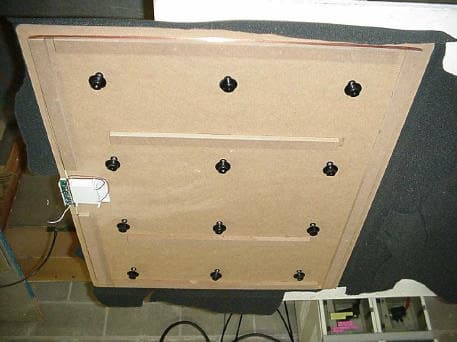
Click to zoom
Application Details
- Equipment Class
- DCD - Part 15 Low Power Transmitter Below 1705 kHz
- Date of Grant
- Jul 05, 2006
- Application Purpose
- Original Equipment
- Date of Application
- Jun 26, 2006
- Equipment Note
- Pet Containment System
- Frequency Range
- 0.01065000 - 0.01065000
- Company
- Radio Systems Corp
- Country
- United States
Documents & Files
Document Text
Text extracted from the exhibit documents filed with the FCC. Open a document above to read the original.
Users Manual
PetSafe ® Wireless Crate ™ Operating and Training Guide Please read this entire guide before beginning B A T T E R Y 6 V R FA - 6 7 2 1-800-732-2677 Thank you for choosing PetSafe ® , the best selling brand of electronic training solutions in the world. Our mission is to be the most trusted brand in the pet ownership experience. We want to ensure your pet’s happiness and safety by providing you with the tools and techniques to successfully train your pet. If you have any questions whatsoever, please contact the Customer Care Center at 1-800-732-2677 or visit our website at www.petsafe.net. We will be there to help you, and we promise your call will be a pleasant experience. ____________________________________________________________________ Table of Contents Introduction ................................................................................................3 Components ...............................................................................................3 How the Wireless Crate ™ Works ....................................................................4 Operating Guide Familiarization and Preparation ................................................................4 Initial Set-Up & Test Instructions ..............................................................5 Training Guide Fit the Receiver Collar ..............................................................................6 Find the Best Stimulation Level for Your Pet ..............................................7 General Tips ............................................................................................7 DAY 1, First Session ................................................................................8 DAY 2, Second Session ............................................................................9 DAYS 3, 4, and 5, Successive Sessions ......................................................9 Frequently Asked Questions ...................................................................... 10 Troubleshooting ........................................................................................ 11 Terms of Use and Limitation of Liability .................................................... 11 FCC Compliance ...................................................................................... 12 CE Compliance......................................................................................... 12 www.petsafe.net 3 Introduction The Wireless Crate offers unsurpassed freedom and daily enjoyment for you and your dog. With the Wireless Crate, there are no cage wires or plastic walls to obstruct you and your dog’s view, as would be the case with a traditional crate. So you and your dog can enjoy each other’s company, without your dog begging at the dinner table or storming the door when guests arrive. The Wireless Crate is portable and enables you to spend time with your dog in places that are customarily off-limits with traditional crates. Imagine the freedom of taking your dog with you to the park, a sporting event, or a friend’s home without the worries of having your dog running off. Components Please take a moment to familiarize yourself with the contents of the kit. You should have received the items shown below. If you fi nd anything missing or in less than optimal condition please call our Customer Care Center at 1-800-732-2677. B A T TER Y 6 V R F A - 6 7 Wireless Crate Receiver Collar Boundary Flags - 2 Operating and Training Guide 4 1-800-732-2677 How the Wireless Crate ™ Works The Wireless Crate is designed to work with existing Radio Systems PetSafe Receiver Collars. If you have a Radio System PetSafe In-Ground Fence, your collar will also work with the Wireless Crate, eliminating the need for separate collars. The Wireless Crate functions by detecting the dog on the crate and signaling the dog through a choice of tone or mild static stimulation if the dog exits the crate without your permission. If the dog leaves the crate without permission while the unit is turned on, the collar will produce either a toned beep to signal your dog or warning beeps accompanied with a mild static stimulation. The correction type depends on the setting you choose. Once the dog returns into the crate, the tonal beep or static stimulation ceases. Preparation and training is required for optimal and safe results. Please continue reading this manual before attempting to use this product with your pet. Operating Guide Familiarization and Preparation Please take a moment to familiarize yourself with the Wireless Crate ™ and its controls before using this product with your pet. Switch The Wireless Crate ™ has a three-way sliding switch that allows you to turn on the unit and control the type of correction. Battery Installation Make sure the switch is in the “OFF” position. Remove the fabric covering the Wireless Crate ™ . Open the battery door and install 4 AA batteries (batteries are not included) as shown below. Replace the battery door and fabric cover. No Beep No Correction Beep Only Beep and Static Correction Indicator Light www.petsafe.net 5 Indicator Light The Indicator Light blinks green to indicate the bed is on and ready for use. If the light is red, the crate is not operating properly. Check the batteries. If the batteries are good and the light is still red, please contact our Customer Care Center at 1-800-732-2677. Training Flags Place the training fl ags in the small sleeves provided in the fabric cover. Once your dog is trained to the Wireless Crate ™ , you may remove the fl ags. ____________________________________________________________________ Initial Set-Up & Test Instructions 1. Set the Wireless Crate ™ on a fi rm, fl at, dry surface. The Wireless Crate ™ is designed to be used for supervised outdoor application, but is not waterproof. 2. Move the switch to Beep Only ( ) . The Indicator Light should blink green every 2 seconds. 3. Place your hand on the Wireless Crate ™ and hold of the Re…
Text truncated - open the document above for the full version.
Cover Letter(s)
Confidentiality Request 11/8/05 AmericanTCB 6731 Whittier Ave McLean, VA 22101 FCC ID: KE3-WC100 In regard to the exhibits submitted in support of the application for FCC ID: KE3-WC100 please classify the following as confidential under the provision of 47 CFR 0.459: • Schematics • Block Diagram These exhibits contain technical information which Radio Systems deems to be sensitive and proprietary. Therefore this information cannot be published. If this information were to be made public it could be used to the disadvantage of the applicant in the marketplace. Louis A. Feudi Operations Manager US Technologies (US Tech Authorized Agent for Radio Systems) 3505 Francis Circle Alpharetta, GA 30004 PH: 770-740-0717 Fax: 770-740-1508 www.ustech-lab.com
Cover Letter(s)
4/21/2006 Mr. Doug Noble ATCB RE: Radio System Corporation FCC ID: KE3-WC100 IC: 2721A-WC100 Below are my responses to your comments on this Application. FCC: 1. Please supply corrected FCC ID label. Form 731 shows a dash between the grantee code and the certification number. The label in the exhibit does not show this dash. If the dash should not be included in the FCC ID number please revise and upload the Form 731. Label revised and uploaded 2. In the test report 4 models are covered. If they are different in size, etc. You will need to provide photos showing the difference between the four models. Differences between the models are only associated with the size of the bed area. Antenna length is identical for each unit, however, number of turns vary based upon the size of the bed. Since the wire length is the same, the small bed has the most number of turns, although the loop size is smaller. The large bed has the least number of turns, yet the loop size is larger. The PCB and circuit placement is identical for all four beds. Sample photos of the small bed is provided illustrate the similarities of the beds. 3. Please revise test report to include Information clearly identifying which model was found to be worse case and how it was tested. Below is the modification of the test report: Measurements were made using a peak detector. Field strength of the peak fundamental emission is shown in Figure 4. For purposes of this test, the EUT was set to a maximum duty cycle, maximum TX power, and 10.65 kHz transmit frequency. Testing of the 10.65 kHz Electro-magnetic field was conducted with the EUT transmitting continuously at the max field condition, at 3505 Francis Circle Alpharetta, GA 30004 PH: 770-740-0717 Fax: 770-740-1508 www.ustech-lab.com a distance of 1 meter, using the loop antenna. All four units were tested for Fundamental field Strength and Harmonics and the worst case unit was tested to represent all units. Each unit was placed upon the turntable, rotated, and maximum fundamental field strength was observed and plotted with the loop antenna in X, Y, and Z Axis orientation, at a 1 m height. Copies of these plots are on file at U.S. Technologies. Spurious Harmonic Emissions were reviewed, and the worst case Harmonics values observed corresponded with the Maximum Fundamental Frequency. Data for the worst case configuration has been provided. The worst case model was the PW17-10799, the X-Large Wireless Crate. 4. Please revise test report stating methods and showing photos of how the manipulation of loop antenna per ANSI C63.4 2003 was accomplished. See above. Due to lack of original sample, the photos cannot be provided. However, the description above details positioning of the antenna IC: 1. Industry Canada label should be "IC:" not "CAN:". Label should have dash between Company Number and Unique Product Number. Please upload a new Label exhibit. Revised and uploaded 2. In the test report please show test data to support Emissions designator for IC? Revised and uploaded, data inadvertently left out. 3. Please provide REL listing letter. Uploaded. Please contact me with any further questions. Louis A. Feudi Vice President, Operations and Engineering
External Photos
SECTION 5 PHOTOGRAPHS PHOTOS OF THE TESTED EUT Photo 1.EUT, Top View , Felt Cover Removed Photo 2. EUT, Bottom View, Felt Cover Removed Photo 1. EUT, Top View, Felt Cover Removed Photo 2. EUT, Bottom View, Felt Cover Removed
ID Label/Location Info
This device complies with Part 15 of the FCC rules. Operation is subject to the following two conditions: 1. This device must not cause harmful interference. 2. This device must accept any interference received including interference that may cause undesired operation. Model: PWC17-10789 SWR-0 Read instruction manual before use. Do not expose to water FOR USE ONLY WITH RADIO SYSTEMS UNDERGROUND FENCE RECEIVERS. FCC ID: KE3-WC100 IC: 2721A-WC100 Made in China for: Radio Systems Corporation 10427 Electric Avenue Knoxville, TN 37932 1 800 732-2677 www.petsafe.net Patent Pending 402-1511 Label Placement Photo 1:EUT Top View, Felt Cover Removed Label
Internal Photos
SECTION 5 PHOTOGRAPHS PHOTOS OF THE TESTED EUT Photo 3.EUT, Cover Removed Photo 4. Mother Board, Solder Side Photo 5. Mother Board, Component Side Photo 6.Antenna Photo 3. EUT Photo 4. Mother Board, Solder Side Photo 5. Mother Board, Component Side Photo 6. Antenna Small Bed Control Wires Small Bed Cover Removed Small Bed Weight Sensors Covered Small Bed Weight Sensors and Control Board
Operational Description
How the Wireless Crate™ Works The Wireless Crate is designed to work with existing Radio Systems PetSafe Receiver Collars. If you have a Radio System PetSafe In-Ground Fence, your collar will also work with the Wireless Crate, eliminating the need for separate collars. The Wireless Crate functions by detecting the dog on the crate and signaling the dog through a choice of tone or mild static stimulation if the dog exits the crate without your permission. If the dog leaves the crate without permission while the unit is turned on, the collar will produce either a toned beep to signal your dog or warning beeps accompanied with a mild static stimulation. The correction type depends on the setting you choose. Once the dog returns into the crate, the tonal beep or static stimulation ceases. Preparation and training is required for optimal and safe results. Please continue reading this manual before attempting to use this product with your pet.
Test Report
Radio Systems Corporation FCC Part 15, Certification Report Wireless Crate PW17-10796 -Small Wireless Crate, PW17-10797- Medium Wireless Crate, PW17-10798 - Large Wireless Crate and PW17-10799 -X- Large Wireless Crate Test Date(s): October 7 & 21, 2005 UST Project: 05-0267 Issue Date: December 12, 2005 3505 Francis Circle Alpharetta, GA 30004 PH: 770-740-0717 Fax: 770-740-1508 www.ustech-lab.com FCC ID: KE3-WC100 U.S. Technologies, Inc.Test Report, Part 15 Rev: 040103 Report Number:05-0267Issue Date: December 12, 2005 Customer: Radio Systems Corporation Model: PW17-10796 -Small Wireless Crate, PW17-10797- Medium Wireless Crate, PW17-10798 - Large Wireless Crate and PW17-10799 -X- Large Wireless Crate 1 MEASUREMENT/TECHNICAL REPORT This report concerns (check one): Original grant X Class II change_ _ Equipment type: Low Frequency, Low Power Transmitter Deferred grant requested per 47 CFR 0.457(d)(1)(ii)? yes_____ No X If yes, defer until:_________________ date N.A. agrees to notify the Commission by NA date of the intended date of announcement of the product so that the grant can be issued on that date. Report prepared by: United States Technologies, Inc. 3505 Francis Circle Alpharetta, GA 30004 Phone Number: (770) 740-0717 Fax Number: (770) 740-1508 FCC ID: KE3-WC100 U.S. Technologies, Inc.Test Report, Part 15 Rev: 040103 Report Number:05-0267Issue Date: December 12, 2005 Customer: Radio Systems Corporation Model: PW17-10796 -Small Wireless Crate, PW17-10797- Medium Wireless Crate, PW17-10798 - Large Wireless Crate and PW17-10799 -X- Large Wireless Crate 2 TABLE OF CONTENTS SECTION 1 Agency Agreement Confidentiality GENERAL INFORMATION Product Description Related Submittal(s) Grant(s) SECTION 2 TESTS AND MEASUREMENTS Configuration of Tested Test Facility Test Equipment Modifications Field Strength of Fundamental Emission Field Strength of Spurious Emissions Radiated Emissions Power Line Conducted Emissions SECTION 3 LABELING INFORMATION SECTION 4 BLOCK DIAGRAM/SCHEMATICS SECTION 5 PHOTOGRAPHS SECTION 6 USER'S MANUAL FCC ID: KE3-WC100 U.S. Technologies, Inc.Test Report, Part 15 Rev: 040103 Report Number:05-0267Issue Date: December 12, 2005 Customer: Radio Systems Corporation Model: PW17-10796 -Small Wireless Crate, PW17-10797- Medium Wireless Crate, PW17-10798 - Large Wireless Crate and PW17-10799 -X- Large Wireless Crate 3 LIST OF FIGURES AND TABLES FIGURES Test Configuration Photograph(s) for Spurious and Fundamental Emissions TABLES EUT And Peripherals Test Instruments Field Strength of Fundamental Emission Field Strength of Spurious Emissions Radiated Emissions Power Line Conducted Emissions 20 dB Bandwidth FCC ID: KE3-WC100 U.S. Technologies, Inc.Test Report, Part 15 Rev: 040103 Report Number:05-0267Issue Date: December 12, 2005 Customer: Radio Systems Corporation Model: PW17-10796 -Small Wireless Crate, PW17-10797- Medium Wireless Crate, PW17-10798 - Large Wireless Crate and PW17-10799 -X- Large Wireless Crate 4 SECTION 1 GENERAL INFORMATION FCC ID: KE3-WC100 U.S. Technologies, Inc.Test Report, Part 15 Rev: 040103 Report Number:05-0267Issue Date: December 12, 2005 Customer: Radio Systems Corporation Model: PW17-10796 -Small Wireless Crate, PW17-10797- Medium Wireless Crate, PW17-10798 - Large Wireless Crate and PW17-10799 -X- Large Wireless Crate 5 GENERAL INFORMATION Product Description The Equipment Under Test (EUT) is the Radio Systems Corporation’s Wireless Crate Models: PW17-10796 -Small Wireless Crate, PW17-10797- Medium Wireless Crate, PW17-10798 - Large Wireless Crate and PW17-10799 -X- Large Wireless Crate. The EUT a pet containment system consisting of a transmitting bed and receiver collar. The bed detects the weight of the pet and does not transmit if pet is detected. Once the pet leaves the bed, a signal is transmitted to the receiver collar. The bed can transmit either a beep only signal or a correction signal to the receiver. Once the pet returns to the bed, the transmission signal will turn off. The bed will only transmit for a maximum of 8 seconds, if the pet does not return to the bed. All four units are identical in construction. The units differ by the number of turns at the antenna. However, all four units utilize the same antenna length. Related Submittal(s) Grant(s) The EUT is subject to the following authorization: a)Certification as a low power transmitter (10.65 kHz) The information contained in this report is presented for the Certification authorization for the transmitter portion of the EUT. FCC ID: KE3-WC100 U.S. Technologies, Inc.Test Report, Part 15 Rev: 040103 Report Number:05-0267Issue Date: December 12, 2005 Customer: Radio Systems Corporation Model: PW17-10796 -Small Wireless Crate, PW17-10797- Medium Wireless Crate, PW17-10798 - Large Wireless Crate and PW17-10799 -X- Large Wireless Crate 6 SECTION 2 TESTS AND MEASUREMENTS FCC ID: KE3-WC100 U.S. Technologies, Inc.Test Report, Part 15 Rev: 040103 Report Number:05-0267Issue Date: December 12, 2005 Customer: Radio Systems Corporation Model: PW17-10796 -Small Wireless Crate, PW17-10797- Medium Wireless Crate, PW17-10798 - Large Wireless Crate and PW17-10799 -X- Large Wireless Crate 7 TESTS AND MEASUREMENTS Configuration of Tested System The sample was tested per ANSI C63.4, Methods of Measurement from Low-Voltage Electrical and Electronic Equipment in the Range of 30 MHz -1 GHz (1992). Radiated emissions data was taken with the test receiver or spectrum analyzer's resolution bandwidth adjusted to 100 Hz (9 kHz – 150 kHz), 9kHz (150 kHz - 30 MHz), and 120 kHz (30 MHz - 1 GHz) respectively. All measurements are peak unless stated otherwise. The video filter associated with the spectrum analyzer was off throughout the evaluation process. Interconnect- ing cables were manipulated as necessary to maximize emissions. A block diagram of the tested system is shown in Figure 1. Test configuration photographs for spurious and fundamental emissions are shown in Figure 2. Results below 100 kHz were corrected to …
Text truncated - open the document above for the full version.
Test Setup Photos
FIGURE 2a Photograph(s) for Spurious and Fundamental Emissions FIGURE 2b Photograph(s) for Spurious and Fundamental Emissions FIGURE 2c Photograph(s) for Conducted Emissions NOT APPLICABLE BATTERY POWERED
Contact Information
Applicant
Deborah J. LeMaster(Regulatory Compliance Specialist)
Technical Contact
US TechLouis Feudi
[email protected]770-740-0717
3505 Francis Circle · Alphareatta, Georgia · United States
Test Firm
US TechGeorge Yang
Technical Specifications
| # | Rule Parts | Frequency Range | Power Output |
|---|---|---|---|
| 1 | 15C | 0.01065 MHz - 0.01065 MHz | - |
Other Applications from Radio Systems Corp

KE3-PIF150-2
Jun 18, 2026Stay & Play Wireless Fence
Equipment Class
DCD - Part 15 Low Power Transmitter Below 1705 kHz
KE3-3003841
Jun 05, 2026PetSafe HydroSphere 60 oz Cordless Fountain
Equipment Class
FDS - Part 15 Field Disturbance Sensor
KE3-3003832
Apr 08, 2026GPS Tracker Collar
Equipment Class
DTS - Digital Transmission System
KE3-3003791
Jul 01, 2024MURS radio device
Equipment Class
TNB - Licensed Non-Broadcast Station Transmitter
KE3-3003803
Apr 06, 2024Dog Training Collar
Equipment Class
DSC - Part 15 Security/Remote Control Transmitter