KE3IF101PetSafe Wireless Pet Containment System
Radio Systems Corp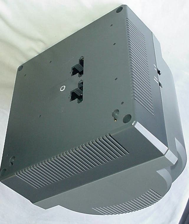
Click to zoom
Application Details
- Equipment Class
- DCD - Part 15 Low Power Transmitter Below 1705 kHz
- Date of Grant
- Jun 16, 2005
- Application Purpose
- Original Equipment
- Date of Application
- Jun 16, 2005
- Equipment Note
- PetSafe Wireless Pet Containment System
- Frequency Range
- 0.01870000 - 0.01870000
- Company
- Radio Systems Corp
- Country
- United States
Documents & Files
Document Text
Text extracted from the exhibit documents filed with the FCC. Open a document above to read the original.
Users Manual
PetSafe ® Wireless Pet Containment System ™ Operating and Training Guide Please read this entire guide before beginning H A P P Y O W N E R S S A F E P E T S 2 1-800-732-2677 Thank you for choosing PetSafe ® , the #1 selling brand of electronic training solutions in the world. Our mission is to ensure your pet’s safety by providing you the tools and techniques to successfully train your pet. If you have any questions, please contact the Customer Care Center at 1-800-732-2677 or visit our website at www.petsafe.net. ___________________________________________ Table of Contents Components ....................................................................................................................................3 Other Items You May Need ...............................................................................................................3 How the System Works .....................................................................................................................4 Key Defi nitions ................................................................................................................................4 Operating Guide Set Up the Transmitter ...................................................................................................................5 Prepare the Receiver Collar ............................................................................................................5 Adjust the Pet Area to Desired Size ................................................................................................6 Transmitter Range Chart ...............................................................................................................7 Place the Boundary Zone Flags ......................................................................................................7 Fit the Receiver Collar ...................................................................................................................8 Training Guide Be Patient With Your Pet ................................................................................................................9 Day 1 – Boundary Flag Awareness ..................................................................................................9 Days 2 thru 4 – Continue Boundary Flag Awareness ..................................................................... 10 Days 5 thru 8 – Distraction Phase ................................................................................................ 10 Days 9 thru 14 – Unleashed Supervision ....................................................................................... 11 Taking Your Pet Out of the Pet Area .............................................................................................. 11 Wireless - To - Go ........................................................................................................................ 12 Accessories .................................................................................................................................... 12 Frequently Asked Questions ........................................................................................................... 12 Troubleshooting ............................................................................................................................. 14 Test Light Instructions ................................................................................................................... 15 Terms of Use and Limitation of Liability ......................................................................................... 15 FCC .............................................................................................................................................. 16 Caution ......................................................................................................................................... 16 Mounting Template ........................................................................................................................ 16 www.petsafe.net 3 Components Boundary Flags - 50 Power Adapter Test Light Long Contact Points Transmitter Operating and Training Guide H A P P Y O W N E R S S A F E P E T S Warranty Card Warranty Receiver Collar w/Short Contact Points Battery (PetSafe ® RFA-67) Other Items You May Need • Pliers • Scissors • Lighter • Drill & mounting hardware • Tape measure • Non-metallic collar and leash 4 1-800-732-2677 Note: In many neighborhoods, nearby property lines may limit how large the Pet Area can be. Maximum 90 ft. range (45 average steps) PET AREA Transmitter Key Definitions Transmitter: Transmits the radio signal and is the center of the Pet Area. Pet Area: Distance from the Transmitter where your pet can roam freely. Boundary Zone: 2 to 3 foot wide area outside the Pet Area where your pet’s Receiver Collar will begin to beep and then begin to deliver a Static Correction. The correction will start in the Boundary Zone and continue anywhere beyond the Pet Area. Note: The Receiver Collar is equipped with a safety time-out feature that will stop correcting after 30 seconds if your pet remains outside the Pet Area. Receiver Collar: Receives the radio signal from the Transmitter. Correction Level Button: Adjusts the level of Static Correction your pet receives outside the Pet Area. Receiver Indicator Light: Indicates the level of correction at which the Receiver Collar is set. This light also serves as a low battery indicator. Contact Points: Deliver the safe Static Correction when your pet moves into the Boundary Zone. Power Jack: Where the Power Adapter plugs into the Transmitter. The Transmitter is powered by a standard 120-volt outlet. Boundary Switch: Adjust according to the size of the Pet Area desired. Power Light: Indicates when the Transmitter is on. Boundary Control Dial: Adjusts the distance from the Transmitter to the Boundary Zone. Note: Adjusting the dial does not change…
Text truncated - open the document above for the full version.
Cover Letter(s)
Confidentiality Request 4/1/05 AmericanTCB 6731 Whittier Ave McLean, VA 22101 FCC ID: KE3IF101 In regard to the exhibits submitted in support of the application for FCC ID: KE3IF101 please classify the following as confidential under the provision of 47 CFR 0.459: • Schematics • Block Diagram These exhibits contain technical information which Radio Systems deems to be sensitive and proprietary. Therefore this information cannot be published. If this information were to be made public it could be used to the disadvantage of the applicant in the marketplace. Louis A. Feudi Operations Manager US Technologies (US Tech Authorized Agent for Radio Systems)
Cover Letter(s)
American Telecommunications Certification Body Inc. 6731 Whittier Ave, McLean, VA 22101 April 23, 2005 RE: FCC ID: KE3IF101_ATCB002329 Attention: Lou Feudi I have a few comments on this Application. Please note that further comments may arise in response to answers provided to the questions below. 1. Please provide a separate operational description for this device. 2. Please provide a manual with the necessary non-modification statement and user information statements in accordance with 15.21 and 15.105. 3. Please note that devices operating with a fundamental frequency below 30MHz MUST have radiated measurements performed using a magnetic loop antenna. Please note that, while you report lists a loop antenna in the equipment list, your setup photos show that a log periodic antenna was used. Please retest the device using the proper magnetic loop antenna for frequencies below 30MHz. 4. Please note that on the plot on page 13 of the report (page 15 of the pdf file) there are two similar appearing wave forms. The peak of the fundamental that you list is lower than the peak of the signal to the right of this supposed fundamental. Please note that if this is a signal from the device it fails as the fundamental is not the highest emission as required by 15.209c. Please explain this second signal and please verify that the fundamental is the highest signal in relation to ALL harmonics and spurious emissions from the device. 5. Please note that the 731 form states the fundamental is 18.7kHz however, the report on page 14 (page 16 of the pdf file) states the device fundamental is 19.5kHz. Please be consistent as to the operating characteristics of the device. Please correct as necessary. 6. Please note that while on page 17 of the report (page 18 of the pdf) you state that no emissions were found within 20dB of the limit, you must still show that no spurious emissions exceeded the fundamental regardless of the proximity to the limits. Please verify and provide evidence that no harmonic or other spurious emission was greater than the fundamental emissions. . Dennis Ward mailto:[email protected] The items indicated above must be submitted before processing can continue on the above referenced application. Failure to provide the requested information may result in application termination. Correspondence should be considered part of the permanent submission and may be viewed from the Internet after a Grant of Equipment Authorization is issued. Please do not respond to this correspondence using the email reply button. In order for your response to be processed expeditiously, you must submit your documents through the AmericanTCB.com website. Also, please note that partial responses increase processing time and should not be submitted. Any questions about the content of this correspondence should be directed to the sender.
Cover Letter(s)
ATCB Mr. Dennis Ward RE: FCC ID: KE3IF101_ATCB002329 I have a few comments on this Application. Please note that further comments may arise in response to answers provided to the questions below. 1. Please provide a separate operational description for this device. Uploaded 2. Please provide a manual with the necessary non-modification statement and user information statements in accordance with 15.21 and 15.105. Revised and Uploaded 3. Please note that devices operating with a fundamental frequency below 30MHz MUST have radiated measurements performed using a magnetic loop antenna. Please note that, while you report lists a loop antenna in the equipment list, your setup photos show that a log periodic antenna was used. Please retest the device using the proper magnetic loop antenna for frequencies below 30MHz. Retested and report revised 4. Please note that on the plot on page 13 of the report (page 15 of the pdf file) there are two similar appearing wave forms. The peak of the fundamental that you list is lower than the peak of the signal to the right of this supposed fundamental. Please note that if this is a signal from the device it fails as the fundamental is not the highest emission as required by 15.209c. Please explain this second signal and please verify that the fundamental is the highest signal in relation to ALL harmonics and spurious emissions from the device. The fundamental plot was a result of ambient noise, which was confirmed on our site by powering down the EUT and unplugging the plug-in power supply. However, the fundamental was re- measured and a better plot has been provided in the test report. 5. Please note that the 731 form states the fundamental is 18.7kHz however, the report on page 14 (page 16 of the pdf file) states the device fundamental is 19.5kHz. Please be consistent as to the operating characteristics of the device. Please correct as necessary. The correction of the fundamental plot using the loop antenna has corrected this discrepency. 6. Please note that while on page 17 of the report (page 18 of the pdf) you state that no emissions were found within 20dB of the limit, you must still show that no spurious emissions exceeded the fundamental regardless of the proximity to the limits. Please verify and provide evidence that no harmonic or other spurious emission was greater than the fundamental emissions. Report revised and uploaded. Please contact me with any further concerns that you may have. Sincerely, Louis A. Feudi Operations and Engineering Manager
External Photos
EXTERNAL PHOTOGRAPHS PHOTOS OF THE TESTED EUT Photo 1.EUT, Front View Photo 2. EUT, Back View Photo 1. EUT, Front View Photo 2. EUT, Back View
ID Label/Location Info
IF-101 MFG. DATE 38400 S 402-1275/0 FOR USE ONLY WITH INSTANT FENCE RECEIVERS WARNING: Risk of fire or electric shock. Connect only to UL listed Class 2 transformer for supply connection. Output 14VAC 1.8A CAUTION: Risk of electric shock. Install transmitter indoors. Do not expose to rain. This device complies with part 15 of the FCC Rules. Operation is subject to the following two conditions: 1. This device must not cause harmful interference. 2. This device must accept any interference received including interference that may cause undesired operation. FCC ID: KE3IF101 CAN: 2721A-IF101 Patent Number 6,879,300 Other Patents Pending NOTES:: 1: MFG Date to be issued using the Excel Date Coding System 1900. Number will be automatically generated. For Example: February 17, 2005 = 38400 March 17, 2005 = 38428 April 17, 2005 = 38459 2: MFG ID code letter: For example: S= SUGA W= WHITWAYS 3: Do not print box. Dimensions are for placement only. 4: Tolerance = +/-.010“ 2.02" 1.02" Project:IF-101 Description:LABEL, HOUSING BOTTOM, IF-101 RSC Part:402-1275 0 Revision: Revision Desription: RSC File Name:402-1275 Adobe IllustratorCS Date:4-19-05 Material: Drawn By:JS .008 Rigid white vinyl, .001 polyester overlamination Black Print on White Background Approval: D.C. Color: Date: Radio Systems The world leader in pet training products C O R P O R A T I O N
Internal Photos
INTERNAL PHOTOGRAPHS PHOTOS OF THE TESTED EUT Photo 3.EUT, Open View Photo 4. Mother Board, Component Side Photo 5. Mother Board, Solder Side Photo 6. Control Board, Component Side Photo 7. Control Board, Solder Side Photo 8.Antenna Photo 3. EUT, Open View Photo 4. Mother Board, Component Side Photo 5. Mother Board, Solder Side Photo 6. Control Board, Component Side Photo 7. Control Board, Solder Side Photo 8. Antenna
Operational Description
IF-101 Theory of Operation The IF-101 Transmitter is designed to transmit an electromagnetic field in all directions as a method of containing a pet, which wears a receiver collar with means of correction, within a predetermined area. The size of the containment area is based on the Boundary Switch and Boundary Control dial settings. The consumer is able to adjust the range of the containment area to fit the size of their yard. The maximum range is approximately 90 feet. As long as the pet stays within the containment area, the receiver collar receives the signal from the transmitter and no warning tone or static correction is delivered to the pet. If the pet tries to leave the containment area and the receiver collar loses the signal from the transmitter, the pet receives a warning tone and a static correction in order to keep it within the containment area. Once the pet returns to the containment area and the receiver collar acquires the transmitter signal, the warning beep and static correction is stopped, and the pet knows he is within the containment area. As a safety precaution if the pet does not return to the containment area, the receiver collar will stop the static correction after 30 seconds. The IF-101 Transmitter also has a 5 second power up delay built into the ASIC. This was added into the design to prevent the receiver collar from delivering a false static correction during power failures and when the power “flickers”. The IF-101 Transmitter frequency is 18.72kHz, has a bandwidth of 30Hz, and uses phase modulation. The transmit time it continuous and has continuous output power regulation.
Test Report
Radio Systems Corporation FCC Part 15, Certification Report Model IF-101 Transmitter Test Date(s): April 1 & 6, 2005 UST Project: 05-0115 Issue Date: April 13, 2005 FCC ID: KE3IF101 U.S. Technologies, Inc.Test Report, Part 15 Rev: 040103 Report Number:05-0115Issue Date: April 13, 2005 Customer: Radio Systems Corporation Model: IF-101 Transmitter MEASUREMENT/TECHNICAL REPORT This report concerns (check one): Original grant X Class II change_ _ Equipment type: Low Frequency, Low Power Transmitter Deferred grant requested per 47 CFR 0.457(d)(1)(ii)? yes_____ No X If yes, defer until:_________________ date N.A. agrees to notify the Commission by NA date of the intended date of announcement of the product so that the grant can be issued on that date. Report prepared by: United States Technologies, Inc. 3505 Francis Circle Alpharetta, GA 30004 Phone Number: (770) 740-0717 Fax Number: (770) 740-1508 FCC ID: KE3IF101 U.S. Technologies, Inc.Test Report, Part 15 Rev: 040103 Report Number:05-0115Issue Date: April 13, 2005 Customer: Radio Systems Corporation Model: IF-101 Transmitter 1 TABLE OF CONTENTS SECTION 1 Agency Agreement Confidentiality GENERAL INFORMATION Product Description Related Submittal(s) Grant(s) SECTION 2 TESTS AND MEASUREMENTS Configuration of Tested Test Facility Test Equipment Modifications Field Strength of Fundamental Emission Field Strength of Spurious Emissions Radiated Emissions Power Line Conducted Emissions SECTION 3 LABELING INFORMATION SECTION 4 BLOCK DIAGRAM/SCHEMATICS SECTION 5 PHOTOGRAPHS SECTION 6 USER'S MANUAL FCC ID: KE3IF101 U.S. Technologies, Inc.Test Report, Part 15 Rev: 040103 Report Number:05-0115Issue Date: April 13, 2005 Customer: Radio Systems Corporation Model: IF-101 Transmitter 2 LIST OF FIGURES AND TABLES FIGURES Test Configuration Photograph(s) for Spurious and Fundamental Emissions TABLES EUT And Peripherals Test Instruments Field Strength of Fundamental Emission Field Strength of Spurious Emissions Radiated Emissions Power Line Conducted Emissions FCC ID: KE3IF101 U.S. Technologies, Inc.Test Report, Part 15 Rev: 040103 Report Number:05-0115Issue Date: April 13, 2005 Customer: Radio Systems Corporation Model: IF-101 Transmitter 3 SECTION 1 GENERAL INFORMATION FCC ID: KE3IF101 U.S. Technologies, Inc.Test Report, Part 15 Rev: 040103 Report Number:05-0115Issue Date: April 13, 2005 Customer: Radio Systems Corporation Model: IF-101 Transmitter 4 GENERAL INFORMATION Product Description The Equipment Under Test (EUT) is the IF-101 Transmitter. The EUT is part of a system that is used for pet containment to a specific area. The EUT transmits an Electro-magnetic signal circular in area that establishes the area for the pet to move about. The pet wears a receiver collar that detects the signal from the transmitter. When the pet is out of range of the transmitter, the pet will receive a static correction so that the pet will stay within the specified area. Testing of the 18.7 kHz Electro-magnetic field was conducted with the EUT transmitting continuously at the max field condition. Related Submittal(s) Grant(s) The EUT is subject to the following authorization: a)Certification as a low power transmitter (18.7 kHz) The information contained in this report is presented for the Certification authorization for the transmitter portion of the EUT. FCC ID: KE3IF101 U.S. Technologies, Inc.Test Report, Part 15 Rev: 040103 Report Number:05-0115Issue Date: April 13, 2005 Customer: Radio Systems Corporation Model: IF-101 Transmitter 5 SECTION 2 TESTS AND MEASUREMENTS FCC ID: KE3IF101 U.S. Technologies, Inc.Test Report, Part 15 Rev: 040103 Report Number:05-0115Issue Date: April 13, 2005 Customer: Radio Systems Corporation Model: IF-101 Transmitter 6 TESTS AND MEASUREMENTS Configuration of Tested System The sample was tested per ANSI C63.4, Methods of Measurement from Low-Voltage Electrical and Electronic Equipment in the Range of 30 MHz -1 GHz (1992). Conducted and radiated emissions data were taken with the test receiver or spectrum analyzer's resolution bandwidth adjusted to 100 Hz (9 kHz – 150 kHz), 9kHz (150 kHz - 30 MHz), and 120 kHz (30 MHz - 1 GHz) respectively. All measurements are peak unless stated otherwise. The video filter associated with the spectrum analyzer was off throughout the evaluation process. Interconnecting cables were manipulated as necessary to maximize emissions. A block diagram of the tested system is shown in Figure 1. Test configuration photographs for spurious and fundamental emissions are shown in Figure 2. Results below 100 kHz were corrected to 300 meters by the following 40 log (300/3) - 80 dB (which has been applied to other submittals and is allowed per previous discussions with Greg Czumak at the FCC). Test Facility Conducted and digital device testing was performed at US Tech's measurement facility at 3505 Francis Circle, Alpharetta, GA. Test Equipment Table 2 describes test equipment used to evaluate this product. Modifications No modifications were made to bring the EUT into compliance with FCC Part 15, Class B Requirements. FCC ID: KE3IF101 U.S. Technologies, Inc.Test Report, Part 15 Rev: 040103 Report Number:05-0115Issue Date: April 13, 2005 Customer: Radio Systems Corporation Model: IF-101 Transmitter 7 FIGURE 1 TEST CONFIGURATION 120 VAC/ 60Hz Direct Plug In Transmitter (EUT) 6’ U Power Cable Adapter FCC ID: KE3IF101 U.S. Technologies, Inc.Test Report, Part 15 Rev: 040103 Report Number:05-0115Issue Date: April 13, 2005 Customer: Radio Systems Corporation Model: IF-101 Transmitter 8 FIGURE 2a Photograph(s) for Spurious and Fundamental Emissions FCC ID: KE3IF101 U.S. Technologies, Inc.Test Report, Part 15 Rev: 040103 Report Number:05-0115Issue Date: April 13, 2005 Customer: Radio Systems Corporation Model: IF-101 Transmitter 9 FIGURE 2b Photograph(s) for Spurious and Fundamental Emissions FCC ID: KE3IF101 U.S. Technologies, Inc.Test Report, Part 15 Rev: 040103 Report Number:05-0115Issue Date: April 13, 2005 Customer: Radio Systems…
Text truncated - open the document above for the full version.
Test Setup Photos
FIGURE 2a Photograph(s) for Spurious and Fundamental Emissions FIGURE 2b Photograph(s) for Spurious and Fundamental Emissions FIGURE 2c Photograph(s) for Conducted Emissions
Contact Information
Applicant
Deborah J. LeMaster(Regulatory Compliance Specialist)
Technical Contact
Test Firm
US TechGeorge Yang
Technical Specifications
| # | Rule Parts | Frequency Range | Power Output |
|---|---|---|---|
| 1 | 15C | 0.0187 MHz - 0.0187 MHz | - |
Other Applications from Radio Systems Corp

KE3-PIF150-2
Jun 18, 2026Stay & Play Wireless Fence
Equipment Class
DCD - Part 15 Low Power Transmitter Below 1705 kHz
KE3-3003841
Jun 05, 2026PetSafe HydroSphere 60 oz Cordless Fountain
Equipment Class
FDS - Part 15 Field Disturbance Sensor
KE3-3003832
Apr 08, 2026GPS Tracker Collar
Equipment Class
DTS - Digital Transmission System
KE3-3003791
Jul 01, 2024MURS radio device
Equipment Class
TNB - Licensed Non-Broadcast Station Transmitter
KE3-3003803
Apr 06, 2024Dog Training Collar
Equipment Class
DSC - Part 15 Security/Remote Control Transmitter