KE3TC100Pet Containment System
Radio Systems Corp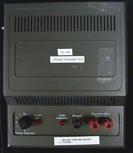
Click to zoom
Application Details
- Equipment Class
- DCD - Part 15 Low Power Transmitter Below 1705 kHz
- Date of Grant
- Nov 15, 1999
- Application Purpose
- Original Equipment
- Date of Application
- Sep 28, 1999
- Equipment Note
- Pet Containment System
- Frequency Range
- 0.01070000 - 0.01070000
- Company
- Radio Systems Corp
- Country
- United States
Documents & Files
Document Text
Text extracted from the exhibit documents filed with the FCC. Open a document above to read the original.
Users Manual
FCC ID: KE3TC100 FCC ID: KE3TC100 FCC ID: KE3TC100 FCC ID: KE3TC100 FCC ID: KE3TC100 FCC ID: KE3TC100 FCC ID: KE3TC100 FCC ID: KE3TC100 FCC ID: KE3TC100 FCC ID: KE3TC100 FCC ID: KE3TC100 FCC ID: KE3TC100 FCC ID: KE3TC100 FCC ID: KE3TC100
Users Manual
Deluxe Remote Trainer Owner’s Manual Changes made to the old Remote Trainer Owner’s Manual for new manual Front Page Change picture to reflect dog with new receiver Components Add to the list of “Components” – receiver batteries, long probes Add picture instead of drawing displaying the components Assemble Collar Change instructions to the following: To assemble the collar, first measure your pet’s neck, mark the appropriate length, and cut off any excess collar. Seal the edge of the cut by taking a match or lighter along the frayed edge. Note: When cutting off the excess collar, be sure to leave enough slack for your dog’s growth. When threading your collar through the clasp, loop it through the clasp exactly as illustrated. Pull on the excess collar. If it slides at all, it was not looped correctly. If your dog has long or thick hair, the longer probes might be more effective in delivering the stimulation to your dog. If the dog still has trouble feeling the stimulation even with the longer probes, the dog’s hair will need to be trimmed. This can be done either by a veterinarian, or you can do it yourself. Add new threading instructions Install Batteries The transmitter takes one (1) 9-Volt Alkaline battery. To install, follow the instructions listed below: • Place your finger on top of the “Pull” area of the battery door, located on the backside of the transmitter. • Now remove the battery door by pulling your finger towards you. • Insert the battery and replace the battery door. The receiver takes two (2) 3-Volt Lithium batteries (Model 2032). To install, follow the instructions listed below: • With a Philips screwdriver, remove the two screws located on top of the receiver. • Remove the battery door and insert the two batteries into the battery door as shown in the drawing below. • Insert battery door with batteries back into the receiver and secure it with the two screws. Turning the Deluxe Remote Trainer On/Off To turn the receiver on, slowly connect the white dots located on both the receiver and transmitter and separate. Upon separating, the receiver will emit one short beep. Note: Once the receiver has been activated, the receiver must be manually turned off by following the instructions shown below. To turn the receiver off, slowly connect the white dots located on both the receiver and transmitter, hold for three (3) seconds, and separate. Upon separating, the receiver will emit a long beep indicating the unit has been turned off. Add picture(s) of transmitters displaying each step. Add same drawing that is for the Ultralight receiver in the Owners guide for the fence system. Add new pictures showing white dots. Setting the Stimulation Level To set the stimulation level, hold down the “Program” button. After a few seconds, the receiver will indicate the present stimulation level by beeping a number of times corresponding to the current level. For instance, for level 1, the receiver will beep one time. For level 8, the receiver will beep eight times. Continue to hold the “Program” button down until the number of beeps equals the level of stimulation you want. After Level 8, the receiver will go back to Level 1. Once the receiver has been programmed to the desired stimulation level, the receiver will remember that level whether the unit has been turned off or with the batteries replaced. Placing the Collar on Your pet Keep everything except last statement. Maintenance Check batteries (weekly) NOTE: This equipment has been tested and found to comply with the limits for a Class B digital device, pursuant to Part 15 of the FCC Rules. These limits are designed to provide reasonable protection against harmful interference when the equipment is operated in a residential environment. This equipment generates, uses, and can radiate radio frequency energy and, if not installed and used in accordance with the instruction manual, may cause harmful interference to radio communications. However, there is no guarantee that interference will not occur in a practical installation. If this equipment does cause harmful interference to radio or television reception, which can be determined by turning the equipment off and on, the user is encouraged to try to correct the interference by one or more of the following measures: -Reorient or relocate the receiving antenna. -Increase the separation between the equipment and receiver. -Connect the equipment into an outlet on a circuit different from that to which the receiver is connected. -Consult the dealer or an experienced radio/TV technician for help. Unauthorized changes or modifications to the equipment, not approved by PetSafe, could result in not meeting compliance with FCC regulations and could void the user’s authority to operate the equipment. Radio Systems Corporation, 10427 Electric Ave, Knoxville, TN 37932 1-800-732-2677www.petsafe.net Add picture of new transmitter
Cover Letter(s)
FCC ID: KE3TC100
External Photos
PHOTOS OF THE TESTED EUT Photo 1.Front View of EUT Photo 2. Back View of EUT Photo 3.Top View of EUT Photo 4. Bottom View of EUT Photo 5.Internal View of EUT When Opened Photo 6. Main Board Bottom Side Photo 7. Top View of Receiver Board Plus Cable Assembly Photo 8.Bottom View of Receiver Board Plus Cable Assembly Photo 9. Top View of Receiver Board Photo 10.Bottom View of Receiver Board Photo 1.Front View of EUT Photo 2. Back View of EUT Photo 3.Top View of EUT FCC ID: KE3TC100 Photo 4. Bottom View of EUT
ID Label/Location Info
FCC ID: KE3TC100 SECTION 3 LABELING INFORMATION FCC ID: KE3TC100 FCC ID: KE3TC100 FCC ID: KE3TC100
Internal Photos
FCC ID: KE3TC100 FCC ID: KE3TC100 Photo 5.Internal View of EUT When Opened FCC ID: KE3TC100 Photo 6. Main Board Bottom Side FCC ID: KE3TC100 Photo 7. Top View of Receiver Board Plus Cable Assembly FCC ID: KE3TC100 Photo 8.Bottom View of Receiver Board Plus Cable Assembly FCC ID: KE3TC100 Photo 9. Top View of Receiver Board FCC ID: KE3TC100 Photo 10.Bottom View of Receiver Board
Schematics
FCC ID: KE3TC100 FCC ID: KE3TC100 FCC ID: KE3TC100
Test Report
MEASUREMENT/TECHNICAL REPORT COMPANY NAME:Radio Systems Corporation MODEL:TC-100 FCC ID:KE3TC100 DATE:August 30, 1999 This report concerns (check one): Original grant X Class II change_ _ Equipment type: Low Power Transmitter Deferred grant requested per 47 CFR 0.457(d)(1)(ii)? yes_____ No X If yes, defer until:_________________ date N.A. agrees to notify the Commission by N.A. date of the intended date of announcement of the product so that the grant can be issued on that date. Report prepared by: United States Technologies, Inc. 3505 Francis Circle Alpharetta, GA 30004 Phone Number: (770) 740-0717 Fax Number: (770) 740-1508 FCC ID: KE3TC-100 TABLE OF CONTENTS SECTION 1 GENERAL INFORMATION Product Description Related Submittal(s) Grant(s) SECTION 2 TESTS AND MEASUREMENTS Configuration of Tested Test Facility Test Equipment Modifications Field Strength of Fundamental Emission Field Strength of Spurious Emissions Radiated Emissions Power Line Conducted Emissions SECTION 3 LABELING INFORMATION SECTION 4 SCHEMATICS SECTION 5 PHOTOGRAPHS SECTION 6 USER'S MANUAL FCC ID: KE3TC100 LIST OF FIGURES AND TABLES FIGURES Test Configuration Photograph(s) for Spurious and Fundamental Emissions TABLES EUT And Peripherals Test Instruments Field Strength of Fundamental Emission Field Strength of Spurious Emissions Power Line Conducted Emissions FCC ID: KE3TC100 GENERAL INFORMATION Product Description The Equipment Under Test (EUT) is a Radio Systems Corporation, Model TC-100 Pet Training and Containment System. The EUT incorporates a 303.825 MHz receiver and a 10.7 kHz dog fence transmitter. The receiver accepts commands from a small handheld transmitter. This report covers only the transmitter (dog fence) portion of the device. Related Submittal(s) Grant(s) The EUT is subject to the following authorizations: a) Certification as a low power receiver (10.7 kHz) b) Certification or DoC, as a low power receiver (303.825 MHz) The information contained in this report is presented for the Certification authorization for the transmitter portion of the EUT. A separate report has been generated for the DoC authorization of the receiver portion of the EUT. The EUT will also be used with a hand-held transmitter submitted and previously approved under FCC ID: PPT101. FCC ID: KE3TC100 TESTS AND MEASUREMENTS Configuration of Tested System The sample was tested per ANSI C63.4, Methods of Measurement from Low-Voltage Electrical and Electronic Equipment in the Range of 30 MHz -1 GHz (1992). Conducted and radiated emissions data were taken with the test receiver or spectrum analyzer's resolution bandwidth adjusted to 100 Hz (9 kHz – 150 kHz), 9kHz (150 kHz - 30 MHz), and 120 kHz (30 MHz - 1 GHz) respectively. All measurements are peak unless stated otherwise. The video filter associated with the spectrum analyzer was off throughout the evaluation process. Interconnecting cables were manipulated as necessary to maximize emissions. A block diagram of the tested system is shown in Figure 1. Test configuration photographs for spurious and fundamental emissions are shown in Figure 2. The EUT was set up with a 300' length of wire connected to it, to simulate a typical installation. The wire was not buried, as it would be in a typical installation (approximately 2 -3 inches). Measurements were taken at all three antenna polarities on each side of the square and intervals in between, at a distance of 3 meters. The side with the worst case results was re-measured at a distance of 10 meters. Results between 100 kHz and 30 MHz were corrected to 30 meters by the following 40 log (300/10) = 59.1 dB. Those results below 100 kHz were corrected to 300 meters by the following 60 log (300/10) = 88.6 dB (which is allowed per previous discussion with Greg Czumak at the FCC). Test Facility Conducted testing was performed at US Tech's measurement facility as described to the FCC and acknowledged in their letter marked 31040/SIT/USTECH. Additional radiated testing was performed at a vacant area that would allow measurements to be made 10 meters away from the EUT with the 300' length of wire connected to it. Test Equipment Table 2 describes test equipment used to evaluate this product. Modifications No modifications were made to bring the EUT into compliance with FCC Part 15, Class B Requirements: FCC ID: KE3TC100 FIGURE 1 TEST CONFIGURATION Dog Fence Transmitter EUT 6’U 60 Hz Source 300 ‘ U FCC ID: KE3TC100 FIGURE 2 Photograph(s) for Spurious and Fundamental Emissions FCC ID: KE3TC100 FIGURE 2 Photograph(s) for Spurious and Fundamental Emissions FCC ID: KE3TC100
Test Report
FCC ID: KE3TC100 FIGURE 2 Photograph(s) for Spurious and Fundamental Emissions FCC ID: KE3TC100 FIGURE 2 Photograph(s) for Spurious and Fundamental Emissions FCC ID: KE3TC100 FIGURE 2 Photograph(s) for Spurious and Fundamental Emissions FCC ID: KE3TC100 FIGURE 2 Photograph(s) for Spurious and Fundamental Emissions FCC ID: KE3TC100 FIGURE 2 Photograph(s) for Spurious and Fundamental Emissions FCC ID: KE3TC100 FIGURE 2 Photograph(s) for Spurious and Fundamental Emissions FCC ID: KE3TC100
Test Report
FIGURE 2 Photograph(s) for Spurious and Fundamental Emissions FIGURE 2 Photograph(s) for Spurious and Fundamental Emissions FIGURE 2 Photograph(s) for Spurious and Fundamental Emissions FIGURE 2 Photograph(s) for Spurious and Fundamental Emissions FIGURE 2 Photograph(s) for Conducted Emissions EUT and Peripherals PERIPHERAL MANUFACTURER MODEL NUMBER SERIAL NUMBER FCC ID:CABLES P/D Dog Fence Transmitter Radio Systems Corporation (EUT) TC-100NoneKE3TC100 (Pending) 300' U TABLE 2 TEST INSTRUMENTS TYPEMANUFACTURERMODELSN. SPECTRUM ANALYZERHEWLETT-PACKARD8593E3205A00124 SPECTRUM ANALYZERHEWLETT-PACKARD8558B2332A09900 S A DISPLAYHEWLETT-PACKARD853A2404A02387 COMB GENERATORHEWLETT-PACKARD8406A1632A01519 RF PREAMPHEWLETT-PACKARD8447D1937A03355 RF PREAMPHEWLETT-PACKARD8449B3008A00480 HORN ANTENNAEMCO31153723 BICONICAL ANTENNAEMCO31109307-1431 LOOP ANTENNAAH SYSTEMSSAS200/5 62 142 LOG PERIODIC ANTENNA EMCO31469110-3600 LISNSOLAR ELE.8028N/A THERMOMETERFLUKE525215250 MULTIMETERFLUKE8553710469 FUNCTION GENERATOR TEKTRONIXCFG250CFG250TW15059 PLOTTERHEWLETT-PACKARD7475A2325A65394 BILOGCHASECBL6112A2238 Field Strength of Fundamental Emission (47 CFR 15.209) Measurements were made using a peak detector. Field strength of the peak fundamental emission is shown in Tables 3 and 4. Duty Cycle Correction During 100 msec: Each setting sends a different series of characters, but the worse case transmit cycle consists of 20.5 ms of transmit time every 35.5 ms (57.7 % Duty Cycle). Figure 3 shows the characteristics of the pulse train for one of the various functions. Duty Cycle Correction = 20 log (0.577) = -4.8 dB Figure 3 TABLE 3a FIELD STRENGTH OF FUNDAMENTAL EMISSION Test Date:August 21, 1999 UST Project:99-623 Customer:Radio Systems Corporation Model:TC-100 FREQ. (kHz) TEST DATA (dBm) @ 10m ANTENNA FACTOR + CABLE ATTENUATION PEAK RESULTS (uV/m) @ 300m PEAK FCC LIMITS (uV/m) @ 300m 10.7-67.577.8 27.12243.0 SAMPLE CALCULATIONS: RESULTS uV/m @ 3m = Antilog ((-67.5 + 77.8 + 107 – 88.6)/20) = 27.1 CONVERSION FROM dBm TO dBuV = 107 dB CORRECTION FROM 10m TO 300m = -88.6 dB Test Results Reviewed By: Name: Tim R. Johnson TABLE 3b FIELD STRENGTH OF FUNDAMENTAL EMISSION Test Date:August 21, 1999 UST Project:99-623 Customer:Radio Systems Corporation Model:TC-100 FREQ. (kHz) TEST DATA* (dBm) @ 10m ANTENNA FACTOR + CABLE ATTENUATION AVERAGE RESULTS (uV/m) @ 300m AVERAGE FCC LIMITS (uV/m) @ 300m 10.7-72.377.8 15.6224.3 * = Corrected for worse case duty cycle, 20 log (0.577) = -4.8 dB SAMPLE CALCULATIONS: RESULTS uV/m @ 3m = Antilog ((-72.3 + 77.8 + 107 – 88.6)/20) = 15.6 CONVERSION FROM dBm TO dBuV = 107 dB CORRECTION FROM 10m TO 300m = -88.6 dB Test Results Reviewed By: Name: Tim R. Johnson Field Strength Of Spurious Emissions (47 CFR 15.209) Measurements were made using a peak detector. Field strength of Spurious Emissions are shown in Table 4. For all emission measurements made the limits given in 15.209 were applied. TABLE 4a FIELD STRENGTH OF SPURIOUS EMISSIONS Test Date:August 21, 1999 UST Project:99-623 Customer:Radio Systems Corporation Model:TC-100 Peak Reading (<30 MHz) FREQ. (kHz.) TEST DATA (dBm) @ 10m ANTENNA FACTOR + CABLE ATTENUATION PEAK RESULTS (uV/m) @ 300m PEAK FCC LIMITS (uV/m) @ 300m 21.4-98.571.90.381121.4 31.9-104.0**70.10.17752.3 53.2-103.064.50.10451.1 ** = Ground Floor SAMPLE CALCULATIONS: RESULTS uV/m @ 3m = Antilog ((-98.5 + 71.9 + 107 – 88.6)/20) = 0.38 CONVERSION FROM dBm TO dBuV = 107 dB CORRECTION FROM 10m TO 300m = -88.6 dB Test Results Reviewed By: Name: Tim R. Johnson TABLE 4b FIELD STRENGTH OF SPURIOUS EMISSIONS Test Date:August 21, 1999 UST Project:99-623 Customer:Radio Systems Corporation Model:TC-100 Average Reading (<30 MHz) FREQ. (kHz.) TEST DATA* (dBm) @ 10m ANTENNA FACTOR + CABLE ATTENUATION AVERAGE RESULTS (uV/m) @ 300m AVERAGE FCC LIMITS (uV/m) @ 300m 21.4-103.371.90.22112.1 31.9-108.870.10.1075.3 53.2-105.864.50.2645.1 * = Corrected for worse case duty cycle, 20 log (0.577) = -4.8 dB SAMPLE CALCULATIONS: RESULTS uV/m @ 3m = Antilog ((-103.3 + 71.9 + 107 – 88.6)/20) = 0.22 CONVERSION FROM dBm TO dBuV = 107 dB CORRECTION FROM 10m TO 300m = -88.6 dB Test Results Reviewed By: Name: Tim R. Johnson TABLE 5 FIELD STRENGTH OF SPURIOUS EMISSIONS (47 CFR 15.209) CLASS B Test Date:August 13, 1999 UST Project:99-623 Customer:Radio Systems Corporation Model:Model TC-100 TX Mode Tested 30 MHz – 1 GHz Frequency (MHz) Test Data (dBm) @3m Ant. Factor + Cable Atten. - Amp Gain Results (uV/m) FCC Limits (uV/m) @3m Margin Below FCC Limit (dB) No signals were seen from the EUT between the range of 30 MHz to 1 GHz Test Results Reviewed By: Name: Tim R. Johnson Power Line Conducted Emissions (47 CFR 15.107a) Conducted Emissions were evaluated from 450 kHz to 30 MHz. Measurements were made with the analyzer's bandwidth set to 9 kHz, emissions are shown in Table 6. The EUT was checked with a 300' fence length. FCC ID: KE3TC100 TABLE 6 CONDUCTED EMISSIONS DATA CLASS B Test Date:August 13, 1999 UST Project:99-623 Customer:Radio Systems Corporation Model:TC-100 FREQUENCY (MHz) TEST DATA (dBm) PHASE NEUTRAL RESULTS (uV) PHASE NEUTRAL FCC LIMITS (uV) .47-73.0-70.050.170.8250 .97-74.0-75.044.739.8250 1.26-74.0-76.044.735.5250 9.55-84.0-88.014.18.9250 9.99-81.0-87.020.010.0250 11.76-78.0-83.028.215.8250 SAMPLE CALCULATIONS: RESULTS uV = Antilog ((-73.0 + 107)/20) = 50.1 CONVERSION FROM dBm TO dBuV = 107 dB Test Results Reviewed By: Name: Tim R. Johnson
Contact Information
Applicant
Deborah J. LeMaster(Regulatory Compliance Specialist)
Technical Contact
United States TechnologiesTimothy R Johnson
[email protected]770-740-0717
3505 Francis Circle · Alpharetta, Georgia · United States
Non-Technical Contact
United States TechnologiesTimothy R Johnson
[email protected]770-740-0717
Test Firm
US TechSandy McEnery
Technical Specifications
| # | Rule Parts | Frequency Range | Power Output |
|---|---|---|---|
| 1 | 15C | 0.0107 MHz - 0.0107 MHz | - |
Other Applications from Radio Systems Corp

KE3-PIF150-2
Jun 18, 2026Stay & Play Wireless Fence
Equipment Class
DCD - Part 15 Low Power Transmitter Below 1705 kHz
KE3-3003841
Jun 05, 2026PetSafe HydroSphere 60 oz Cordless Fountain
Equipment Class
FDS - Part 15 Field Disturbance Sensor
KE3-3003832
Apr 08, 2026GPS Tracker Collar
Equipment Class
DTS - Digital Transmission System
KE3-3003791
Jul 01, 2024MURS radio device
Equipment Class
TNB - Licensed Non-Broadcast Station Transmitter
KE3-3003803
Apr 06, 2024Dog Training Collar
Equipment Class
DSC - Part 15 Security/Remote Control Transmitter