KE3TXRF1010Pet Containment System
Radio Systems Corp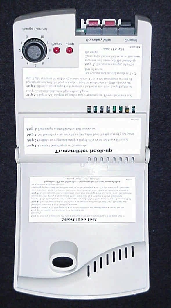
Click to zoom
Application Details
- Equipment Class
- DCD - Part 15 Low Power Transmitter Below 1705 kHz
- Date of Grant
- Dec 18, 2000
- Application Purpose
- Original Equipment
- Date of Application
- Dec 18, 2000
- Equipment Note
- Pet Containment System
- Frequency Range
- 0.01065000 - 0.01065000
- Company
- Radio Systems Corp
- Country
- United States
Documents & Files
Document Text
Text extracted from the exhibit documents filed with the FCC. Open a document above to read the original.
Users Manual
FCC ID: KE3TXRF1010 SECTION 6 USER’S MANUAL FCC ID: KE3TXRF1010 FCC ID: KE3TXRF1010 FCC ID: KE3TXRF1010 FCC ID: KE3TXRF1010 FCC ID: KE3TXRF1010 FCC ID: KE3TXRF1010 FCC ID: KE3TXRF1010 FCC ID: KE3TXRF1010 FCC ID: KE3TXRF1010 FCC ID: KE3TXRF1010 FCC ID: KE3TXRF1010 FCC ID: KE3TXRF1010 FCC ID: KE3TXRF1010 FCC ID: KE3TXRF1010 FCC ID: KE3TXRF1010 FCC ID: KE3TXRF1010 FCC ID: KE3TXRF1010
Block Diagram
FCC ID: KE3TXRF1010
External Photos
FCC ID: KE3TXRF1010 PHOTOS OF THE TESTED EUT Photographs of RF-125 that was originally tested Photo 1.Front View of EUT Photo 2. Back View of EUT Photo 3.Top View of EUT Photo 4. Side View of EUT Showing Slide Switch Photo 5. Side View of EUT Showing DC Input Port Photo 6. Main Board of EUT, PCB Side Photo 7.Main Board of EUT, Solder Side Photographs of EUT (model RF-1010) Photo 8.Front View of EUT Photo 9. Back View of EUT Photo 10.Top View of EUT Photo 11. Side View of EUT Showing Slide Switch Photo 12. Side View of EUT Showing DC Input Port Photo 13. Main Board of EUT, PCB Side Photo 14.Main Board of EUT, Solder Side FCC ID: KE3TXRF1010 Photo 1.Front View of EUT FCC ID: KE3TXRF1010 Photo 2. Back View of EUT FCC ID: KE3TXRF1010 Photo 3.Top View of EUT FCC ID: KE3TXRF1010 Photo 4. Side View of EUT Showing Slide Switch FCC ID: KE3TXRF1010 Photo 5. Side View of EUT Showing DC Input Port FCC ID: KE3TXRF1010 Photo 8.Front View of EUT FCC ID: KE3TXRF1010 Photo 9. Back View of EUT FCC ID: KE3TXRF1010 Photo 10.Top View of EUT FCC ID: KE3TXRF1010 Photo 11. Side View of EUT Showing Slide Switch FCC ID: KE3TXRF1010 Photo 12. Side View of EUT Showing DC Input Port
ID Label/Location Info
FCC ID: KE3TXRF1010 SECTION 3 LABELING INFORMATION FCC ID: KE3TXRF1010 FCC ID: KE3TXRF1010
Internal Photos
FCC ID: KE3TXRF1010 PHOTOS OF THE TESTED EUT Photographs of RF-125 that was originally tested Photo 1.Front View of EUT Photo 2. Back View of EUT Photo 3.Top View of EUT Photo 4. Side View of EUT Showing Slide Switch Photo 5. Side View of EUT Showing DC Input Port Photo 6. Main Board of EUT, PCB Side Photo 7.Main Board of EUT, Solder Side Photographs of EUT (model RF-1010) Photo 8.Front View of EUT Photo 9. Back View of EUT Photo 10.Top View of EUT Photo 11. Side View of EUT Showing Slide Switch Photo 12. Side View of EUT Showing DC Input Port Photo 13. Main Board of EUT, PCB Side Photo 14.Main Board of EUT, Solder Side FCC ID: KE3TXRF1010 Photo 6. Main Board of EUT, PCB Side FCC ID: KE3TXRF1010 Photo 7.Main Board of EUT, Solder Side FCC ID: KE3TXRF1010 Photo 13. Main Board of EUT, PCB Side FCC ID: KE3TXRF1010 Photo 14.Main Board of EUT, Solder Side
Schematics
FCC ID: KE3TXRF1010 FCC ID: KE3TXRF1010
Test Report
Radio Systems Corporation FCC Part 15, Certification Application Model RF-1010 December 15, 2000 MEASUREMENT/TECHNICAL REPORT COMPANY NAME:Radio Systems Corporation MODEL:RF-1010 FCC ID:KE3TXRF1010 DATE:December 15, 2000 This report concerns (check one): Original grant X Class II change_ _ Equipment type: Low Frequency, Low Power Transmitter Deferred grant requested per 47 CFR 0.457(d)(1)(ii)? yes_____ No X If yes, defer until:_________________ date N.A. agrees to notify the Commission by NA date of the intended date of announcement of the product so that the grant can be issued on that date. Report prepared by: United States Technologies, Inc. 3505 Francis Circle Alpharetta, GA 30004 Phone Number: (770) 740-0717 Fax Number: (770) 740-1508 FCC ID: KE3TXPG1010 TABLE OF CONTENTS AGENCY AGREEMENT SECTION 1 GENERAL INFORMATION Product Description Related Submittal(s) Grant(s) SECTION 2 TESTS AND MEASUREMENTS Configuration of Tested Test Facility Test Equipment Modifications Field Strength of Fundamental Emission Field Strength of Spurious Emissions Radiated Emissions Power Line Conducted Emissions SECTION 3 LABELING INFORMATION SECTION 4 BLOCK DIAGRAM/SCHEMATICS SECTION 5 PHOTOGRAPHS SECTION 6 USER'S MANUAL FCC ID: KE3TXRF1010 LIST OF FIGURES AND TABLES FIGURES Test Configuration Photograph(s) for Spurious and Fundamental Emissions TABLES EUT And Peripherals Test Instruments Field Strength of Fundamental Emission Field Strength of Spurious Emissions Power Line Conducted Emissions FCC ID: KE3TXRF1010 SECTION 1 GENERAL INFORMATION FCC ID: KE3TXRF1010 GENERAL INFORMATION Product Description The Equipment Under Test (EUT) is a Radio Systems Corporation Low Frequency, Low Power PetSafe Standard Radio Fence Transmitter, Model RF-1010. The EUT consists of a 10.65 kHz dog fence transmitter. This report covers only the transmitter (dog fence) portion of the device. The EUT is considered to be a identical to a previously approved transmitter (Model RF- 125, FCC ID: KE3TXRF125) except for the following items: 1) The fuse, F1 is removed and replaced with a wire jumper 2) The transient voltage suppressors, TVS1 and TVS2 are removed 3) The three-pin push terminal is replaced with a two-pin push terminal. The additional terminal is for earth ground, but only electrically attaches to the transient voltage suppressors. 4) The housings are identical except the color of the RF-125 is light gray and the RF1010 is dark gray. The fuse access door/compartment has been removed from the bottom housing of the RF-1010 and a plastic insert added to the top housing where the earth ground push terminal was for the RF-125. The EUT is considered to be a subset of the previously approved model. Since difference between the model RF-125 and RF-1010 are not considered to affect the original test results obtained for the RF-125, additional testing on the RF-1010 model was deemed unnecessary. All data supplied in this report is supplied from the certificate application for the model RF-125. FCC ID: KE3TXRF1010 Related Submittal(s) Grant(s) The EUT is subject to the following authorizations: a) Certification as a low power transmitter (10.65 kHz) The information contained in this report is presented for the Certification authorization for the transmitter portion of the EUT. All test data presented in this report is from the previous certification application for the fully configured model RF-125 (FCC ID: KE3TXRF125). FCC ID: KE3TXRF1010 SECTION 2 TESTS AND MEASUREMENTS FCC ID: KE3TXRF1010 TESTS AND MEASUREMENTS Configuration of Tested System The sample was tested per ANSI C63.4, Methods of Measurement from Low-Voltage Electrical and Electronic Equipment in the Range of 30 MHz -1 GHz (1992). Conducted and radiated emissions data were taken with the test receiver or spectrum analyzer's resolution bandwidth adjusted to 100 Hz (9 kHz – 150 kHz), 9kHz (150 kHz - 30 MHz), and 120 kHz (30 MHz - 1 GHz) respectively. All measurements are peak unless stated otherwise. The video filter associated with the spectrum analyzer was off throughout the evaluation process. Interconnecting cables were manipulated as necessary to maximize emissions. A block diagram of the tested system is shown in Figure 1. Test configuration photographs for spurious and fundamental emissions are shown in Figure 2. The EUT was set up with a 320' length of wire connected to it, to simulate a typical installation. The wire was not buried, as it would be in a typical installation (approximately 2 -3 inches). Measurements were taken at all three antenna polarities on each side of the rectangle and intervals in between, at a distance of 3 meters. The side with the worst case results was re-measured at a distance of 10 meters. Results between 100 kHz and 30 MHz were corrected to 30 meters by the following 40 log (300/10) = 59.1 dB. Those results below 100 kHz were corrected to 300 meters by the following 60 log (300/10) = 88.6 dB (which has been applied to other submittals and is allowed per previous discussions with Greg Czumak at the FCC). The EUT is considered to be a identical to a previously approved transmitter (Model RF- 125, FCC ID: KE3TXRF125) except for the following items: 1) The fuse, F1 is removed and replaced with a wire jumper 2) The transient voltage suppressors, TVS1 and TVS2 are removed 3) The three-pin push terminal is replaced with a two-pin push terminal. The additional terminal is for earth ground, but only electrically attaches to the transient voltage suppressors. 4) The housings are identical except the color of the RF-125 is light gray and the RF1010 is dark gray. The fuse access door/compartment has been removed from the bottom housing of the RF-1010 and a plastic insert added to the top housing where the earth ground push terminal was for the RF-125. The EUT is considered to be a subset of the previously approved model. Since difference between the model RF-125 and RF-1010 are not considered to affect the original test results obtained for the …
Text truncated - open the document above for the full version.
Test Setup Photos
FCC ID: KE3TXRF1010 FIGURE 2a Photograph(s) for Spurious and Fundamental Emissions NOTE: Test Results taken from testing of RF-125 (Model RF-1010 is considered a subset) FCC ID: KE3TXRF1010 FIGURE 2b Photograph(s) for Spurious and Fundamental Emissions (Photograph Shows 1 st portion of testing at 3 meters) Note: Personnel taking photograph normally monitored spectrum analyzer during test. FCC ID: KE3TXRF1010 FIGURE 2c Photograph(s) for Spurious and Fundamental Emissions (Photograph Shows 1 st portion of testing at 3 meters) Note: Personnel taking photograph normally monitored spectrum analyzer during test. FCC ID: KE3TXRF1010 FIGURE 2d Photograph(s) for Spurious and Fundamental Emissions (Photograph Shows 1 st portion of testing at 3 meters) Note: Personnel taking photograph normally monitored spectrum analyzer during test. FCC ID: KE3TXRF1010 FIGURE 2e Photograph(s) for Digital Device Emissions NOTE: Test Results taken from testing of RF-125 (Model RF-1010 is considered a subset) FCC ID: KE3TXRF1010 FIGURE 2f Photograph(s) for Digital Device Emissions NOTE: Test Results taken from testing of RF-125 (Model RF-1010 is considered a subset) FCC ID: KE3TXRF1010 FIGURE 2g Photograph(s) for Conducted Emissions NOTE: Test Results taken from testing of RF-125 (Model RF-1010 is considered a subset)
Contact Information
Applicant
Deborah J. LeMaster(Regulatory Compliance Specialist)
Technical Contact
U.S. Technologies, Inc.Timothy R Johnson
[email protected]770 740 0717
3505 Francis Circle · Alpharetta, Georgia · United States
Test Firm
US TechSandy McEnery
Technical Specifications
| # | Rule Parts | Frequency Range | Power Output |
|---|---|---|---|
| 1 | 15C | 0.01065 MHz - 0.01065 MHz | - |
Other Applications from Radio Systems Corp

KE3-PIF150-2
Jun 18, 2026Stay & Play Wireless Fence
Equipment Class
DCD - Part 15 Low Power Transmitter Below 1705 kHz
KE3-3003841
Jun 05, 2026PetSafe HydroSphere 60 oz Cordless Fountain
Equipment Class
FDS - Part 15 Field Disturbance Sensor
KE3-3003832
Apr 08, 2026GPS Tracker Collar
Equipment Class
DTS - Digital Transmission System
KE3-3003791
Jul 01, 2024MURS radio device
Equipment Class
TNB - Licensed Non-Broadcast Station Transmitter
KE3-3003803
Apr 06, 2024Dog Training Collar
Equipment Class
DSC - Part 15 Security/Remote Control Transmitter