KHS900-0001Matrix 100
White's Electronics Inc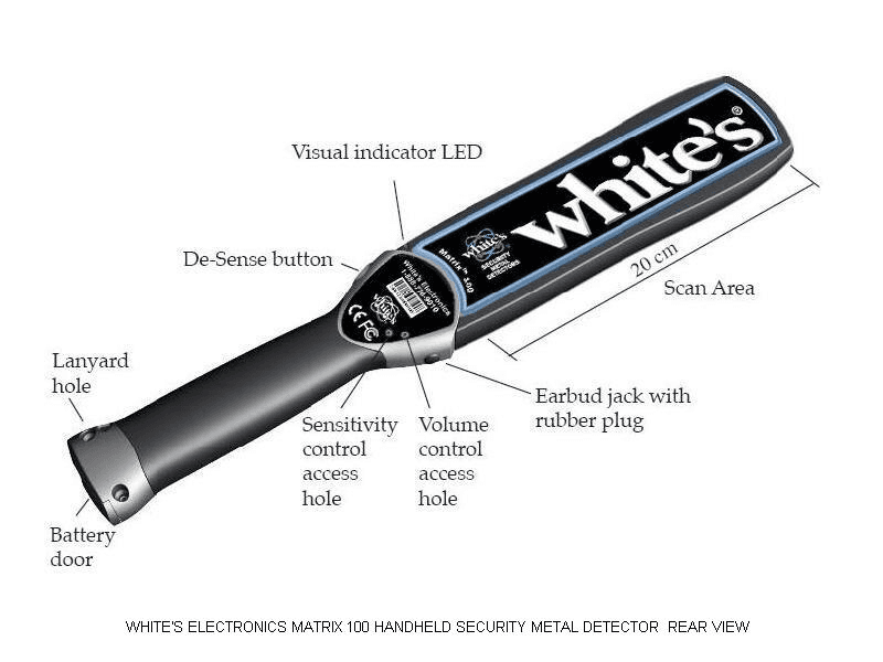
Click to zoom
Application Details
- Equipment Class
- DCD - Part 15 Low Power Transmitter Below 1705 kHz
- Date of Grant
- Feb 18, 2007
- Application Purpose
- Original Equipment
- Date of Application
- Feb 18, 2007
- Equipment Note
- Matrix 100
- Frequency Range
- 0.12200000 - 0.12200000
- Company
- White's Electronics Inc
- Country
- United States
Documents & Files
Document Text
Text extracted from the exhibit documents filed with the FCC. Open a document above to read the original.
Users Manual
3 888-778-9010www.whiteselectronics.com Introduction The Matrix 100 Handheld Metal Detector is a world class security scanner. It is designed to meet and exceed the needs and specifications of today’s security conscious world, and complies with all National Institute of Justice standards for indoor/outdoor operations. “Made in the U.S.A.” is a hallmark of White’s Electronics, the Matrix 100 utilizes the latest in electronic design technology that is both functional and attractive. The Matrix 100 Handheld Metal Detector is designed to detect metal and is primarily for security applications, however it is useful for a myriad of detection applications. Table of Contents Matrix 100 Features Front–View .....................................................................................................4 Back–View ......................................................................................................5 Top Edge .........................................................................................................6 Bottom Edge ...................................................................................................6 Mechanical Drawing-metric Dimensions ..................................................6 Battery Door ...................................................................................................7 ON/OFF Button .......................................................................................................8 Sensitivity Control ..................................................................................................9 Volume Control for Earbud .................................................................................10 Testing the Scanner ...............................................................................................10 Batteries ..................................................................................................................11 Battery Installation ...............................................................................................12 De-sense Button ....................................................................................................13 Earbud Jack ............................................................................................................14 Earbud Jack Rubber Plug .....................................................................................14 Lanyard ..................................................................................................................15 Scanning .................................................................................................................15 Three–year Warranty ............................................................................................19 Specifications .........................................................................................................20 Accessories .............................................................................................................21 Security Distributors ............................................................................................22 Contact Information .............................................................................Back Cover Features – Front view 4 888-778-9010www.whiteselectronics.com Features—Front View Features – Back view ON/OFF button Battery door De-sense button Visual indicator LED Audio speaker ON/OFF LED and Low battery indicator Lanyard hole 5 888-778-9010www.whiteselectronics.com Features—Back View Battery door De-sense button Visual indicator LED Scan area Sensitivity control access hole Volume control access hole Earbud jack with rubber plug Lanyard hole 20 cm 6 888-778-9010www.whiteselectronics.com Features—Top Edge Features—Bottom Edge Mechanical Drawing-metric Dimensions De-sense button Scan area Visual indicator LED Battery door Lanyard hole Scan area Battery door Earbud jack and rubber plug 20 cm 20 cm 7 888-778-9010www.whiteselectronics.com Features—Battery Door Battery door Stylus Battery polarization graphic 8 888-778-9010www.whiteselectronics.com There are three selections for the ON/OFF button: • ON Audio • ON Vibrate • OFF ON Audio—press the ON/OFF button once. This will be followed by a single, double, or triple beep to indicate the current sensitivity level setting. The green ON indicator LED will emit a single flash for low sensitivity, double flash for medium sensitivity or a triple flash for high sensitivity. ON Vibrate—press the ON/OFF button twice. This will be followed by a single vibration burst and the ON indicator LED will emit a single flash for low sensitivity, double flash for medium sensitivity, or a triple flash for high sensitivity. The audio alarm is deactivated when the vibrate alarm is activated. OFF—Turn the unit off by pressing the ON/OFF button once. The ON indicator LED will disappear. ON/OFF indicator LED ON/OFF button Speaker Earbud jack ON/OFF Button 9 888-778-9010www.whiteselectronics.com The unit is preset, at the factory, to medium sensitivity. The sensitivity level can be changed to the low, medium, or high level.* The Specifications List (see Page 20) shows the effect of the different sensitivity levels for detecting objects of various sizes. To change the sensitivity level, open the battery door and remove the stylus (see Page 7). Use the stylus to press the sensitivity control to cycle through the sensitivity levels,(low, medium, or high). The unit will beep or vibrate and will flash the red visual indicator LED to announce the new sensitivity level: One beep/vibration/flash = low sensitivity Two beeps/vibrations/flashes = medium sensitivity Three beeps/vibrations/flashes = high sensitivity When the unit is turned off or the battery is removed, the sensitivity level setting is retained in the memory. Earbud volume Stylus Sensitivity Visual indicator LED De-sense button * To be determined by administration policy and supervisor control. Sensitivity Control…
Text truncated - open the document above for the full version.
Cover Letter(s)
Northwest EMC TCB Compliance Opinion Rev. 9/15/03 WHIT0025 Information about the Applicant Company Name Whites Electronics, Inc. Grantee Thomas V. Scrivner Address 1011 Pleasant Valley Drive City, State, Zip Sweet Home, OR 97386 Job Number WHIT0025 Model Matrix 100 FCC ID KHS900-0001 Agent Northwest EMC Approval Type Original Equipment Class DCD Part 15, low power Tx below 1.705 MHz Rule Part 15C Industry Canada Information Model Matrix 100 Industry Canada ID 6943A-9000001 Rule Part RSS210 Overview White’s Matrix 100 Handheld Security Metal Detector, is a hand-held field-disturbance metal detector. The primary intended application of this product is in commercial or industrial security inspection of objects or persons for detection of concealed metallic objects. The detection field is produced by a planar rectangular coil of about 2 x 8 inch dimensions. The excitation signal is produced by an L-C oscillator having nominal frequency of about 125 KHz, and oscillator DC power input of about 3 mW. Detection range for large metallic objects is about six inches. Operation of the detection field is continuous, and the field is not modulated otherwise. Detection is obtained by measurement of field disturbance; there is not a separate receiver in this device. Detection is announced by visible and audible or vibratory signal. Audio alarm level is typically 85dB at 30 inches. An earphone can optionally be plugged into the package for unobtrusive use of audible annunciation. Operating power is obtained from a self-contained battery. Recommendation All items have been resolved and completed to my satisfaction; therefore I recommend this application for approval. Signature Dave Tolman, TCB Committee 2/18/2007 Northwest EMC TCB Compliance Opinion Rev. 9/15/03 WHIT0025 Findings Specification Finding 47 Cfr 15.19 Labeling Finding The required information was not provided. Resolution The client has provided a revised user manual with the required information.
Cover Letter(s)
Application for Equipment Certification by Northwest EMC TCB Committee TCB-412 Item 2: Cover Letter Describing the Product White’s Electronics Matrix 100 Security Handheld Metal Detector January 24, 2007 The subject device, White’s Matrix 100 Handheld Security Metal Detector, is a hand-held field-disturbance metal detector. The primary intended application of this product is in commercial or industrial security inspection of objects or persons for detection of concealed metallic objects. The detection field is produced by a planar rectangular coil of about 2 x 8 inch dimensions. The excitation signal is produced by an L-C oscillator having nominal frequency of about 125 KHz, and oscillator DC power input of about 3 mW. Detection range for large metallic objects is about six inches. Operation of the detection field is continuous, and the field is not modulated otherwise. Detection is obtained by measurement of field disturbance; there is not a separate receiver in this device. Detection is announced by visible and audible or vibratory signal. Audio alarm level is typically 85dB at 30 inches. An earphone can optionally be plugged into the package for unobtrusive use of audible annunciation. Operating power is obtained from a self-contained battery. The FCC ID is KHS900-0001. The Matrix 100 is a portable device. Approval is sought for this equipment as a 47 CFR Part 15 Unlicensed Radio Frequency Device. Review of Applicable FCC rules: Reference is made to FCC rules, 47 CFR Part 15: Radio Frequency Devices. Reviewing Subparts A, B, C, D, and E: Subpart A General This product matches relevant definitions of Subpart A for unlicensed operation. Subpart B Unintentional Radiators This product contains digital computing electronics, an unintentional radiator. This product is subject to Class B radiated emission limits in order to meet Justice department standards. Therefore, the product will be subject to the Class A radiated emission limits of Part 15, 15.109(a). Subpart C Intentional Radiators This product contains an intentional radiator operating at nom. 125 KHz (acceptance limits are 115/135 KHz min/max). Operating DC power input to the radiating circuit is typically 3 mW. This product matches definitions of 47 CFR Part 15.3 (l): Field disturbance sensor, and 15.3 (o) Intentional radiator. 15.203 Antenna requirement. The antenna is an internal feature of the product, and no provision is made to permit use of any antenna other than that furnished by the manufacturer. 15.205 Restricted bands of operation. A restricted band, 0.090 – 0.110 MHz, is in the vicinity of the operating frequency of this product. Design and production testing of assembled product ensures compliance with this restriction. 15.209 Radiated emission limits of (a) apply. Subpart D Unlicensed Personal Communications Service Devices does not apply. Subpart E Unlicensed National Information Infrastructure Devices does not apply. Contacts General: Tom Scrivner White’s Electronics, Inc. 1011 Pleasant Valley Road Sweet Home, OR 97386 Tel 541-367-6121 ext. 212 email [email protected] Technical: Mike Linse Alpha Omega Computer Systems, Inc. PO Box U Corvallis, OR 97339 Tel 541-754-1911 email [email protected]
Operational Description
White’s Electronics Matrix 100 TCB Certification Submittals for NW EMC TCB412 Jan 30, 2007 TCB412 ITEM 8 ANTENNA INFO (a) The antenna for this device complies with the requirements of 47 CFR 15.203. The antenna is an internal component without provision for change to a substitute antenna, within the meaning of 15.203. (b) Does not apply (c) Does not apply From cover letter: "The detection field is produced by a planar rectangular coil of about 2x8 inch dimensions. The excitation signal is produced by an L-C oscillator having a nominal frequency of about 125 kHz."
RF Exposure Info
White’s Electronics Matrix 100 TCB Certification Submittals for NW EMC TCB412 Jan 30, 2007 TCB412 ITEM 9 RF EXPOSURE LIMITS Applicability of regulations: First, Ref 47 CFR 15.103 Exempted Devices “The following devices are subject only to the general conditions of operation in 15.5 and 15.29 and are exempt from the specific technical standards and other requirements contained in this part.” This product matches the description in 15.103(c) of industrial, commercial, or medical test equipment. Next, Ref 47CFR 1.1310, Radio Frequency radiation exposure limits. This section does not regulate exposure levels at frequencies below 0.3 MHz. Next, Ref 47CFR 2.1093 Radiofrequency radiation exposure evaluation: portable devices. 2.1093(b) includes our device, but 2.1093(c) lists portable devices that are subject to routine environmental evaluation for RF exposure prior to equipment authorization or use. Our device is not among those listed here. “All other portable transmitting devices are categorically excluded from routine environmental evaluation for RF exposure prior to equipment authorization or use, except as specified in §§ 1.1307(c) and 1.1307(d) of this chapter.” Next, Ref. 47CFR 1.1307 (c) and (d) These are exception processes that do not apply to our device. The foregoing observations notwithstanding, it appears that our device is compliant with the exposure limits given in 2.1093 (d) (2), based upon estimated power and field distribution.
Test Report
Whites Electronics, Inc. Matrix 100 February 09, 2007 Report No. WHIT0025 Report Prepared By www.nwemc.com 1-888-EMI-CERT © 2007 Northwest EMC, Inc 22975 NW Evergreen Parkway Suite 400 Hillsboro, Oregon 97124 Certificate of Test Issue Date: February 09, 2007 Whites Electronics, Inc. Model: Matrix 100 Emissions Test Description Specification Test Method Pass Fail Radiated Emissions FCC 15.109:2006 ANSI C63.4:2003 Spurious Radiated Emissions FCC 15.209:2006 ANSI C63.4:2003 Field Strength of Fundamental FCC 15.209:2006 ANSI C63.4:2003 Occupied Bandwidth RSS-Gen, Issue 1:2005 RSS-212, Issue 1 (Provisional):1999 Modifications made to the product See the Modifications section of this report Test Facility The measurement facility used to collect the data is located at: Northwest EMC, Inc. 22975 NW Evergreen Parkway, Suite 400 Hillsboro, OR 97124 Phone: (503) 844-4066 Fax: 844-3826 This site has been fully described in a report filed with and accepted by the FCC (Federal Communications Commission) and Industry Canada. Approved By: Greg Kiemel, Director of Engineering This report must not be used to claim product certification, approval, or endorsement by NVLAP, NIST, or any agency of the federal government of the United States of America. Product compliance is the responsibility of the client, therefore the tests and equipment modes of operation represented in this report were agreed upon by the client, prior to testing. This Report may only be duplicated in its entirety. The results of this test pertain only to the sample(s) tested, the specific description is noted in each of the individual sections of the test report supporting this certificate of test. Northwest EMC Revision History Revision 05/05/03 Revision Number Description Date Page Number 00 None Northwest EMC Accreditations and Authorizations Revision 03/18/05 FCC: Accredited by NVLAP for performance of FCC radio, digital, and ISM device testing. Our Open Area Test Sites, certification chambers, and conducted measurement facilities have been fully described in reports filed with the FCC and accepted by the FCC in letters maintained in our files. Northwest EMC has been accredited by ANSI to ISO / IEC Guide 65 as a product certifier. We have been designated by the FCC as a Telecommunications Certification Body (TCB). This allows Northwest EMC to certify transmitters to FCC specifications in accordance with 47 CFR 2.960 and 2.962. NVLAP: Northwest EMC, Inc. is accredited under the United States Department of Commerce, National Institute of Standards and Technology, and National Voluntary Laboratory Accreditation Program for satisfactory compliance with the requirements of ISO/IEC 17025 for Testing Laboratories. The NVLAP accreditation encompasses Electromagnetic Compatibility Testing in accordance with the European Union EMC Directive 89/336/EEC, ANSI C63.4, MIL- STD 461E, DO-160D and SAE J1113. Additionally, Northwest EMC is accredited by NVLAP to perform radio testing in accordance with the European Union R&TTE Directive 1999/5/EEC, the requirements of FCC, and the RSS radio standards for Industry Canada. NVLAP LAB CODE 200629-0 NVLAP LAB CODE 200630-0 NVLAP LAB CODE 200676-0 Industry Canada: Accredited by NVLAP for performance of Industry Canada RSS and ICES testing. Our Open Area Test Sites and certification chambers comply with RSS 212, Issue 1 (Provisional) and have been filed with Industry Canada and accepted. Northwest EMC has been accredited by ANSI to ISO / IEC Guide 65 as a product certifier. We have been designated by NIST and recognized by Industry Canada as a Certification Body (CB) per the APEC Mutual Recognition Arrangement (MRA). This allows Northwest EMC to certify transmitters to Industry Canada technical requirements. CAB: Designated by NIST and validated by the European Commission as a Conformity Assessment Body (CAB) to conduct tests and approve products to the EMC directive and transmitters to the R&TTE directive, as described in the U.S. - EU Mutual Recognition Agreement. TÜV Product Service: Included in TUV Product Service Group's Listing of Recognized Laboratories. It qualifies in connection with the TUV Certification after Recognition of Agent's Testing Program for the product categories and/or standards shown in TUV's current Listing of CARAT Laboratories, available from TUV. A certificate was issued to represent that this laboratory continues to meet TUV's CARAT Program requirements. Certificate No. USA0604C. TÜV Rheinland: Authorized to carryout EMC tests by order and under supervision of TÜV Rheinland. This authorization is based on "Conditions for EMC-Subcontractors" of November 1992. Northwest EMC Accreditations and Authorizations Revision 03/18/05 NEMKO: Assessed and accredited by NEMKO (Norwegian testing and certification body) for European emissions and immunity testing. As a result of NEMKO's laboratory assessment, they will accept test results from Northwest EMC, Inc. for product certification (Authorization No. ELA 119). Australia/New Zealand: The National Association of Testing Authorities (NATA), Australia has been appointed by the ACA as an accreditation body to accredit test laboratories and competent bodies for EMC standards. Accredited test reports or assessments by competent bodies must carry the NATA logo. Test reports made by an overseas laboratory that has been accredited for the relevant standards by an overseas accreditation body that has a Mutual Recognition Agreement (MRA) with NATA are also accepted as technical grounds for product conformity. The report should be endorsed with the respective logo of the accreditation body (NVLAP). VCCI: Accepted as an Associate Member to the VCCI, Acceptance No. 564. Conducted and radiated measurement facilities have been registered in accordance with Regulations for Voluntary Control Measures, Article 8. (Registration Numbers. - Hillsboro: C-1071, R-1025, C- 2687, T-289, and R-2318, Irvine: C-2094 and R-1943, Sultan: R-871, C-1784, and T-294). BSMI:…
Text truncated - open the document above for the full version.
Test Setup Photos
NORTHWEST EMC FIELD STRENGTH OF FUNDAMENTAL PSA 2007.01.31 NORTHWEST EMC FIELD STRENGTH OF FUNDAMENTAL PSA 2007.01.31 NORTHWEST EMC Radiated Emissions PSA 2007.01.31 NORTHWEST EMC Radiated Emissions PSA 2007.01.31 NORTHWEST EMC OCCUPIED BANDWIDTH XMit 2006.11.13 NORTHWEST EMC Spurious Radiated Emissions PSA 2007.01.31 NORTHWEST EMC Spurious Radiated Emissions PSA 2007.01.31
Contact Information
Applicant
Steve Howard(Customer Service Manager)
Test Firm
Northwest EMC, Inc.Greg Kiemel
Technical Specifications
| # | Rule Parts | Frequency Range | Power Output |
|---|---|---|---|
| 1 | 15C | 0.122 MHz - 0.122 MHz | - |
Other Applications from White's Electronics Inc

KHS800-0353
Jan 20, 2020GMX Series
Equipment Class
DCD - Part 15 Low Power Transmitter Below 1705 kHz
KHS800-0347
Nov 30, 2015MXSport
Equipment Class
DCD - Part 15 Low Power Transmitter Below 1705 kHz
KHS800-0343
Jan 27, 2014Bullseye TRX
Equipment Class
DCD - Part 15 Low Power Transmitter Below 1705 kHzKHS624-0300
Feb 17, 1993Metal Detector
Equipment Class
DCD - Part 15 Low Power Transmitter Below 1705 kHz