KLN313Wireless weather sensor
Maximum Incorporated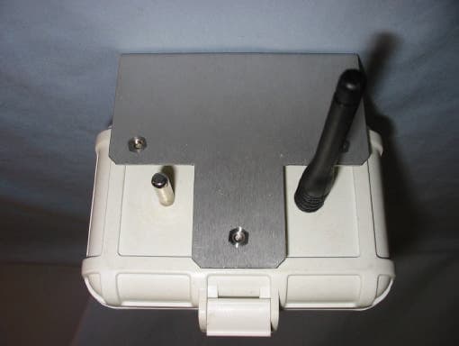
Click to zoom
Application Details
- Equipment Class
- DXX - Part 15 Low Power Communication Device Transmitter
- Date of Grant
- Oct 17, 2002
- Application Purpose
- Original Equipment
- Date of Application
- Oct 17, 2002
- Equipment Note
- Wireless weather sensor
- Frequency Range
- 916.50000000 - 916.50000000
- Company
- Maximum Incorporated
- Country
- United States
Documents & Files
Document Text
Text extracted from the exhibit documents filed with the FCC. Open a document above to read the original.
Users Manual
Maximum Wireless Installation Instructions Introduction Thank you for purchasing A Maximum Wireless Weather instrument. Maximum Wireless Instruments are designed with the customer in mind. It’s ease of installation and operation enables the Do It Yourself consumer to install the instrument. If you need assistance, consult a contractor, electrician, or television antenna installer. Components Receiver Wind Transmitter Temperature Transmitter Rain Transmitter Wiring Pre-Wiring and Test Locations It is important to pre-wire and test operation before final installation can begin. Receiver/Instrument Connect the AC power wires from the Receiver (Blue and Green wires) to the AC Power terminals of the Brass Instrument (DO NOT APPLY POWER). Connect the White wire from the Receiver to terminal #1 (Rx) of the Brass Instrument. Connect the Black wire from the Receiver to terminal #2 (GND) of the Brass Instrument. • If an additional instrument (except Rainwatch, or Cronus) is also being installed use the enclosed jumper wire for connection between instruments. • Connect one end of the WHITE wire to terminal #3 of the 1 st instrument (Tx), and BLACK wire to terminal #2 of the 1 st instrument (GND). • Connect other end of the WHITE wire to terminal #1 of the 2 nd Instrument (Rx), and BLACK wire to terminal #2 of the 2 nd instrument (GND). Receiver/Rainwatch Connect the Yellow wire from the receiver to terminal #4 of the Rainwatch. Connect the Brown wire from the receiver to terminal #5 of the Rainwatch. Maximum Wireless Installation Instructions Cont. Wind Transmitter Insert the two enclosed AA Ni-Cad batteries into the enclosed battery charger (be sure to observe Polarity) and charge batteries for 12 hours. (Do not attempt to charge any batteries other than NI-Cad batteries. This could cause the batteries to explode, possibly causing physical damage or fire). Connect the sensors to the Wind Transmitter wire. Feed the terminal lug end of the Yellow and Brown wires through one of the rubber boots and connect the lugs to the terminals on the bottom of the wind speed sensor using the brass nuts provided. The polarity does not matter. (DO NOT adjust the nuts that are already on the sensor). Feed the terminal lug ends of the wind direction sensor through the other rubber boot. Wire the wind direction sensor as follows: 1=White, 2=Orange, 3=Black, 4=Red, 5=Green Use the Hex nuts provided. (Do NOT adjust the nuts that are already on the wind direction sensor). Slide the stub mast through the rubber boots and insert the stub masts into the bottom of the sensors. Secure with the cotter pins. When connecting the Wind Direction sensor to the Z-mast, make certain that the #3 terminal is aligned with the Z-mast arm. If the sensor is not installed in this manner your wind direction readings will be incorrect. Remove the bottom half of the clamp on the back of the Wind transmitter by loosening the screws. Place the Transmitter on the Wind Direction mast with the antenna above the mast arm. Place bottom of the clamp in back of the mast and secure with the screws that were removed. Secure the sensors and stub masts to your antenna mast (not supplied) with the two hose clamps. Open the Wind Transmitter box by lifting the latches on the box. Place the Jumper to the Test position. (See Diagram) The test position will ensure that the receiver is polling each individual sensor. Temperature Transmitter The Temperature sensor operates on two AA Alkaline batteries (enclosed). Do not connect the batteries yet. Open the Temperature Transmitter box by lifting the latch on the box. Place the Jumper on the Test position. (See Diagram) Rainfall Transmitter The Rainfall sensor operates on two AA Alkaline batteries (enclosed). Do not connect the batteries yet. Remove the top of the Rain Collector by loosening the four Phillips head screws and rotating the top off. Remove the blue cover to access the circuit board. Place the jumper on the Test position. TESTING/SENSOR INSTALLATION Please follow directions in this order Instrument Display Move the Instrument Display near the location where they will be installed. (They may lie on a table or floor for testing). Connect the AC Power adaptor enclosed with the instrument to each specific instrument. If you have 2,3, or 4 instruments wire the AC adaptors to all of the instruments. Plug in all applicable AC Power Adaptors. Merlin you will see all lights light up then NS. Mystic you will see all lights light up then NS. Rainwatch you will See 00.00. Cronus you will see all lights light up then it will display the current time. Rain Transmitter (If Applicable) Install two AA Batteries into the Rain transmitter The Red Light on the Receiver box should light every 4 seconds. Manually tip the dipper on the Rain Collector Base to one side. The Rainwatch display should measure .01” of rain. Move the Collector to final installation location. The Red Light on the Receiver should continue to light every 4 seconds. Manually tip the dipper on the Rain Collector Base and the Rainwatch display should measure .02” of rain. If you loose the signal (Light does not blink), try alternate mounting locations for the Rain Collector. Once location is established remove the batteries, and the test jumper. (Leave Batteries disconnected). Temperature Transmitter (If applicable) Install two AA Batteries into the Temperature transmitter. The Red Light on the Receiver box should light every 4 seconds. Switch the Mystic to display temperature. The instrument should measure the ambient temperature. Move the temperature sensor to final mounting location. (A North exposure 6’ off the ground is recommended). The Red Light on the Receiver should continue to light every 4 seconds. If you loose the signal (Light does not blink), try alternate mounting locations for the temperature sensor. Once location is established remove the battery, and the test jumper. (Leave Battery disconnected). Wind Transmitter Remove the Ni-Cad Batter…
Text truncated - open the document above for the full version.
Cover Letter(s)
Maximum Inc., 30 Samuel Barnet Blvd., New Bedford, MA, 02745, Phone 508-995-2200 October 2, 2002 Federal Communications Commission 7435 Oakland Mills Road Columbia, MD 21046 Gentlemen: This letter is to comply with 47 CFR 0.457(d)(2) pertaining to confidential material. Maximum, Inc. requests that the following documents regarding this submission for FCC ID: KLN313 be kept confidential: 1. Schematic 2. Block Diagram 3. Circuit Description The material above contains technical data, which would customarily be guarded from competitors. Thank You, Paul Hutchinson Chief Engineer Maximum Inc. 30 Samuel Barnet Blvd. New Bedford, MA, 02745
External Photos
External Pictures Model: EA313 FCC ID: KLN313 Model: EA313 FCC ID: KLN313
ID Label/Location Info
(EXCEPT AS NOTED) DECIMAL FRACTIONAL ANGULAR NO. DATEBY REVISIONS TOLERANCES DRAWN BYSCALEMATERIAL DRAWING NO.DATE 30 Samuel Barnet Blvd. New Bedford, MA 02745 [email protected] (508) 995-2200 Inc. FCC ID: KLN313 This device complies with Part 15 of the FCC Rules. Operation is subject to the following two conditions: (1) this device may not cause harmful interference, and (2) this device must accept any interference received, including interference that may cause undesired operation. Temperature Transmitter Temperature Transmitter Labels P.H. 9/24/02 All dimensions in inches 2 2 1 1 See above Material - Polyester with permanent adhesive
Internal Photos
Internal Pictures Model: EA313 FCC ID: KLN313 Model: EA313 FCC ID: KLN313 Model: EA313 FCC ID: KLN313 Model: EA313 FCC ID: KLN313
Contact Information
Applicant
F Nathaniel Bishop(President)
Test Firm
Curtis-Straus LLCJonathan Stewart
Technical Specifications
| # | Rule Parts | Frequency Range | Power Output |
|---|---|---|---|
| 1 | 15C | 916.5 MHz - 916.5 MHz | - |
Other Applications from Maximum Incorporated
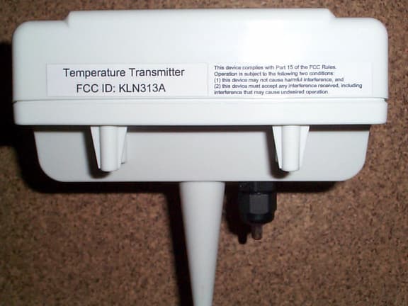
KLN313A
Apr 27, 2006Low Power Communications Transmitter
Equipment Class
DXX - Part 15 Low Power Communication Device Transmitter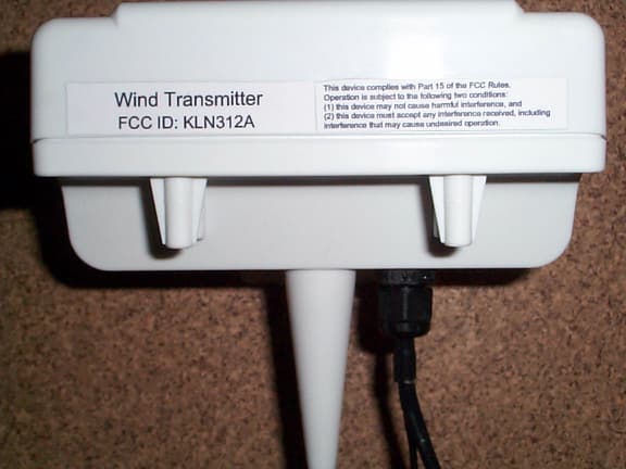
KLN312A
Apr 26, 2006Low Power Communications Transmitter
Equipment Class
DXX - Part 15 Low Power Communication Device Transmitter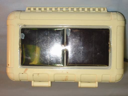
KLN312
Oct 17, 2002Wireless weather sensor
Equipment Class
DXX - Part 15 Low Power Communication Device Transmitter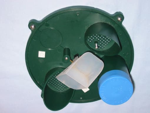
KLN314
Oct 17, 2002Wireless weather sensor
Equipment Class
DXX - Part 15 Low Power Communication Device Transmitter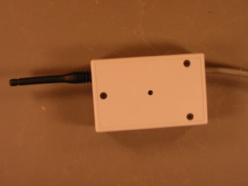
KLN311
Oct 17, 2002Wireless weather instrument
Equipment Class
DXX - Part 15 Low Power Communication Device Transmitter