KLU02597OVC3A On-Van Computer
Mobiltex Data Ltd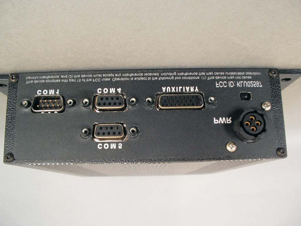
Click to zoom
Application Details
- Equipment Class
- DXX - Part 15 Low Power Communication Device Transmitter
- Date of Grant
- Jun 27, 2002
- Application Purpose
- Original Equipment
- Date of Application
- Jun 27, 2002
- Equipment Note
- OVC3A On-Van Computer
- Frequency Range
- 902.00000000 - 928.00000000
- Company
- Mobiltex Data Ltd
- Country
- Canada
Documents & Files
Document Text
Text extracted from the exhibit documents filed with the FCC. Open a document above to read the original.
Users Manual
CONFIDENTIAL MATERIAL This manual is preliminary information and is subject to change without notice. MOBILTEX DATA LTD.TITLE: Mobiltex OVC3 Hardware User Manual Calgary, AlbertaDOCUMENT NO.: OVC3-MAN-001 SHEET: 1 of 7 REV: 001 Mobiltex OVC3 Hardware User Manual CONFIDENTIAL MATERIAL CONFIDENTIAL MATERIAL This manual is preliminary information and is subject to change without notice. MOBILTEX DATA LTD.TITLE: Mobiltex OVC3 Hardware User Manual Calgary, AlbertaDOCUMENT NO.: OVC3-MAN-001 SHEET: 2 of 7 REV: 001 RESTRICTED PROPRIETARY INFORMATION This information disclosed herein is the exclusive property of Mobiltex Data Ltd. and is not to be disclosed without the written consent of Mobiltex Data Ltd. No part of this publication may be reproduced or transmitted in any form or by any means including electronic storage, reproduction, execution or transmission without the prior written consent of Mobiltex Data Ltd. The recipient of this document by its retention and use, agrees to respect the security status of the information contained herein. This document is intended for limited circulation. The information contained in this document is subject to change without notice and should not be construed as a commitment by Mobiltex Data Ltd. unless such commitment is expressly given in a covering document. © Copyright Mobiltex Data Ltd. 2002 Microsoft, Windows, and Windows CE Logo are either registered trademarks or trademarks of Microsoft Corporation in the United States and/or other countries. All copyrighted, registered, and trademarked material remains the property of their respective owners. REVISION HISTORY RevStart Date Approval Date DescriptionPrepared By 00113 June 2002Preliminary manual released for FCC certification.Scot Kornak CONFIDENTIAL MATERIAL This manual is preliminary information and is subject to change without notice. MOBILTEX DATA LTD.TITLE: Mobiltex OVC3 Hardware User Manual Calgary, AlbertaDOCUMENT NO.: OVC3-MAN-001 SHEET: 3 of 7 REV: 001 Contents 1.Introduction.............................................................................................................................................................................4 2.Front Panel Buttons................................................................................................................................................................4 2.1A – Test Button..............................................................................................................................................................4 2.2B –Reset Button.............................................................................................................................................................4 2.3C – Aux Button...............................................................................................................................................................4 3.Front Panel Indicators............................................................................................................................................................5 3.1LED1 - PWR / Status....................................................................................................................................................5 3.2LED2 – Short Range Wireless.....................................................................................................................................5 3.3LED3 – COM4 Activity................................................................................................................................................5 3.4LED4 – COM5 Activity................................................................................................................................................5 3.5LED5 – General Purpose..............................................................................................................................................5 3.6LED6 – General Purpose..............................................................................................................................................5 3.7LED7 – General Purpose..............................................................................................................................................5 4.Rear Panel Connectors...........................................................................................................................................................6 4.1Power Connector............................................................................................................................................................6 4.2COM1 Serial Port...........................................................................................................................................................6 4.3COM4 Serial Port...........................................................................................................................................................6 4.4COM5 Serial Port...........................................................................................................................................................6 4.5Auxiliary Connector......................................................................................................................................................6 5.Internal Connectors................................................................................................................................................................6 5.1COM3 Serial Port...........................................................................................................................................................6 5.2COM7 Wireless..............................................................................................................................................................6 6.Installation..................................................................................................................................…
Text truncated - open the document above for the full version.
Cover Letter(s)
3640 26 th Street NE Calgary, Alberta T1Y 4T7 Canada Tel: (403) 291-2770, Fax: (403) 250-6795 Web: www.mobiltex.com June 21, 2002 Federal Communications Commission Authorization and Evaluation Division Confidentiality Request regarding application for certification of FCC ID: KLU02597. Pursuant to Sections 0.457 and 0.459 of the Commission’s Rules, we hereby request confidential treatment of information accompanying this application as outlined below: • Mobiltex OVC3A Operational Description • Mobiltex OVC3A Block Diagrams • Mobiltex OVC3A Schematics The above materials contain trade secrets and proprietary information not customarily released to the public. The public disclosure of these materials may be harmful to the applicant and provide unjustified benefits to its competitors. The applicant understands that pursuant to Section 0.457 of the Rules, disclosure of this application and all accompanying documentation will not be made before the date of the Grant for this application. Sincerely, Dale J. Poloway President & General Manager
Test Report
1 TEMPEST INC. 112 Elden Street Herndon, Virginia 20170 (703) “TEMPEST” (836-7378) FAX: 709-9565 e-mail: [email protected] http://www.tempest-inc.com *** Our 17th Year in Business: 1985 - 2002 *** Report of Electromagnetic Interference Testing Performed in Accordance with the Rules of the Federal Communications Commission: Title 47, Part 15 of the Code of Federal Regulations on the Model OVC3A Transceiver made by Mobiltex Data Ltd. 3640 26th Street Northeast, Calgary Alberta, Canada T1Y 4T7 by Louis T. Gnecco, M.S.E.E., President Certified Electromagnetic Compatibility Engineer: Cert.# EMC-000544-NE June 5, 2002 COPYRIGHT 2002 BY TEMPEST INC.: This document may be transmitted electronically to Mobiltex Data Ltd., Timco Engineering, Inc., and to the United States Federal Communications Commission. This document may not be further disseminated, reproduced, recorded electronically, or transmitted electronically, in whole or in part, without the written consent of TEMPEST INC. 2 Abstract 1. As requested by Purchase Order Number 1754 issued by Mobiltex Data Ltd., on June 5, 2002 TEMPEST INC. performed the Electromagnetic Compatibility Tests required by the United States Code Of Federal Regulations, Title 47, Part 15: FCC Rules, Paragraph 15.249: "Operation within the bands 902-928 MHz, 2400-2483.5 MHz, 5725-5875 MHz, and 24.0-24.25 GHz." on the following device made by Mobiltex Data Ltd., hereafter called the Equipment Under Test (EUT): EUT 1: Model OVC3A Transceiver s/n P 0000 9 CSA ID # P 0000 9 FCC ID KLU02597 The Equipment Under Test intentionally radiates signals in the 902-926 MHz band. 2. The Equipment Under Test passed all tests by wide margins of 20 dB or more. 3. The Equipment Under Test was tested in its highest power mode, at the highest, middle and lowest transmitting frequencies. At each frequency, each device was tested in both the "Mark" and "Space" modes.. 3 Table of Contents Section Title Page Cover page 1 Abstract 2 Table of Contents 3 List Of Illustrations 4 List of Tables 4 Reference Documents 4 1.0 Introduction. 5 1.1 Purpose. 5 1.2 Test Location. 5 1.3 Cognizant Personnel. 5 2.0 Description of the Equipment Under Test. 6 3.0 Test Procedures. 7 3.1 Test Equipment. 7 3.2 Calibration Check 7 3.3 Dynamic Range and Detection System Sensitivity Tests. 7 3.4 Local Interference Test. 7 3.5 Measurements. 8 4.0 Results. 9 5.0 Conclusions and Recommendations. 9 Appendix A: Illustrations 10 Appendix B: Tables 11 4 List of Illustrations The following illustrations are submitted electronically as Microsoft Word document: FCC6.doc and the following .jpg files: File Name TITLE Fig-1.jpg Equipment Under Test Fig-2.jpg Equipment Under Test, cover removed. Fig-3.jpg Test Setup: Radiated Emissions List of Tables Table Title Page 1 Instrumentation 11 1A Ancillary Equipment 11 2 Test Data 12 Reference Documents: (a) United States Code Of Federal Regulations, Title 47, Part 15: FCC Rules, Paragraph 15.249: "Operation within the bands 902-928 MHz, 2400-2483.5 MHz, 5725-5875 MHz, and 24.0-24.25 GHz." (b) ANSI C63.4: “American National Standard for Methods of Measurement of Radio-Noise Emissions of Low-Voltage Electrical and Electronic Equipment in the Range of 9 kHz to 40 GHz” IEEE 5 1.0 Introduction. As requested by Purchase Order Number 1754 issued by Mobiltex Data Ltd., on June 5, 2002 TEMPEST INC. performed Electromagnetic Compatibility tests in accordance with References (a) and (b) on the following device, hereafter called the Equipment Under Test: Model OVC3A Transceiver serial number P 0000 9 made by Mobiltex Data Ltd. of Calgary, Alberta 1.1 Purpose. The purpose of this test was to determine if the Equipment Under Test complies with the requirements of Reference (a.). 1.2 Test Location. Testing was performed in the Electromagnetic Compatibility Laboratory and the FCC-listed Open Area Test Site of TEMPEST INC. 1.3 Cognizant Personnel. The following personnel conducted, witnessed, or are cognizant of the test: Mr. Alex Holland Mobiltex Data Ltd. 3640 26th Street Northeast Calgary, Alberta Canada T1Y 4T7 (403) 291-2770 [email protected] : Mr. Jerry Chilibecki, Hardware Engineer, Mobiltex Data Ltd. (403) 291-2770 [email protected] Mr. Louis T. Gnecco, President, TEMPEST INC. 112 Elden St. Herndon, Virginia 20170-4809 (703) 836-7378 e-mail: [email protected] 6 2.0 Description of the Equipment Under Test. The Equipment Under Test consists of a Model OVC3A Transceiver, a vehicle mounted mobile access point device that allows computers in vehicles to communicate using frequency modulation. Each center frequency is varied by + 32 kHz to send a “Mark” and - 32 kHz to send a space. Its maximum output power is + 5 dBm. Its lowest center frequency (mode 1) is 903.018 MHz. Its middle center frequency (mode 2) is 914.998 MHz, and its highest center frequency (mode 3) is 927.1214 MHz. The Equipment Under Test draws 12 Volts of d.c. power, which was supplied by a linear power supply for this test. It is controlled by a laptop computer, which can be disconnected and removed once the desired operating frequency and mode is selected. More information about the Equipment Under Test can be found at the following internet web site: http://www.mobiltex.com 7 3.0 Test Procedures. As described below, final testing was performed in accordance with references (a) and (b.) Radiated emissions were measured. 3.1 Test Equipment. Table 1 is a list of the Instrumentation. Table 1A describes the power supply and laptop computer used as ancillary equipment. A log periodic antenna, and a Hewlett-Packard spectrum analyzer were used in an Open area Test Site (OATS) to detect radiated emissions. 3.2 Calibration Check. Using its internal calibration source, the calibration of the spectrum analyzers was verified both immediately before and immediately after the test. 3.3 Dynamic Range and Detection System Sensitivity Tests. Before testing, the dynamic range of the instrumentation was determined to be 80 dB, an…
Text truncated - open the document above for the full version.
Contact Information
Applicant
Jerry P Chilibecki(Product Engineer)
Test Firm
Tempest Inc.Louis Gnecco
Technical Specifications
| # | Rule Parts | Frequency Range | Power Output |
|---|---|---|---|
| 1 | 15C | 902 MHz - 928 MHz | - |
Other Applications from Mobiltex Data Ltd
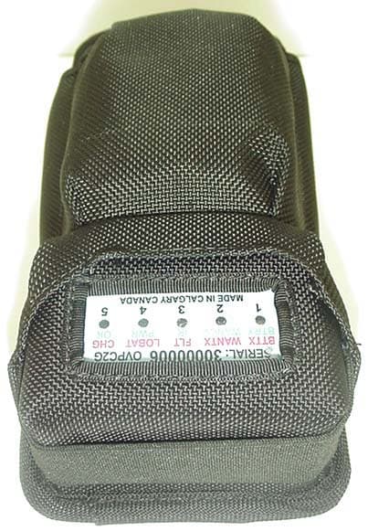
KLU03579
Nov 09, 2003Body-worn Data Transmitter w/Dual-Band GPRS Modem
Equipment Class
PCT - PCS Licensed Transmitter worn on body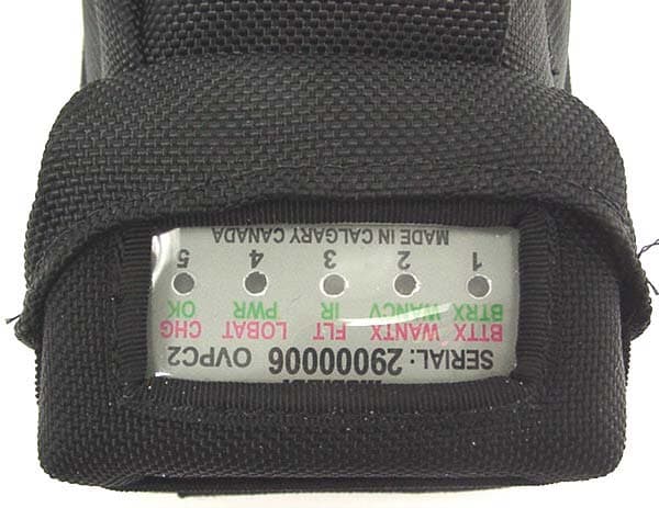
KLU03472
Oct 08, 2003Body-worn Data Transmitter with Internal RF Modem
Equipment Class
TNT - Licensed Non-Broadcast Transmitter Worn on Body