KQGRMIINTERFACE FOR MACHINE TOOLS
Renishaw plcApplication Details
- Equipment Class
- DSS - Part 15 Spread Spectrum Transmitter
- Date of Grant
- Dec 03, 2003
- Application Purpose
- Original Equipment
- Date of Application
- Oct 16, 2003
- Equipment Note
- INTERFACE FOR MACHINE TOOLS
- Frequency Range
- 2400.00000000 - 2483.50000000
- Company
- Renishaw plc
- Country
- United Kingdom
Documents & Files
Select a file to view
Users Manual
Block Diagram
Cover Letter(s)
External Photos
ID Label/Location Info
Internal Photos
Operational Description
Parts List/Tune Up Info
Test Report
Document Text
Text extracted from the exhibit documents filed with the FCC. Open a document above to read the original.
Block Diagram
1 abcdefg COMPANY CONFIDENTIAL PAGE 1 OF 4 Document No: PD- 4113 – 9058Issue: draft ADate: 25 September 2003 Document Title: RMP60 system description and functional block diagrams. Summary/Scope: This document provides a description and block diagram as required by FCC regulations. Reason for Issue/Nature of change: Distribution: Author:Job Title:Signed:Date: M Woollett Radio Group Leader Reviewed by:Job Title:Signed:Date: S Cresson Design Engineer Ren Sa Reviewed by:Job Title:Signed:Date: Approved by:Job Title:Signed:Date: Form No: QA401Issue: 1Date: 10 Aug 93 2 Summary of RMP60 system RMP60 is a point to point touch trigger probe radio transmission system for use on CNC (computer numerically controlled) machine tools. It consists of two components, the RMP (Radio Module Probe) and RMI (Radio Machine Interface) which are the two radio stations. Radio details RMP60 uses FHSS (frequency hopping spread spectrum) transmission in the frequency band from 2402 to 2480 MHz. There are 79 * 1 MHz wide channels. The maximum ERP (emitted radio power) is 1mw (0dBm) and the transmission range is up to 15m. The radio link is bi-directional with half duplex transmission. Both RMP and RMI use a PB31301 Ericsson radio modem. This is a transceiver circuit. When transmitting the modem uses a synthesiser to generate the desired carrier from the 13MHz clock. The modem then modulates this carrier using the input serial data and then amplifies it for transmission to the antenna via a filter. When receiving the signal from the antenna is fed via the filter to a low noise amplifier and then to the built in heterodyne receiver. The synthesiser makes a local oscillator 3MHz below the carrier signal. Following a mixer the signal is demodulated and the resulting serial received data is output . RMP (see Fig 1) The RMP is 63mm diameter, and 76mm long, and has a standard mounting face for fitment to a machine tool shank on one end and a M4 stylus mount on the other. The RMP contains a touch trigger probe similar to the Renishaw MP7 probe module. The RMP is battery powered by 2* AA batteries, the total voltage of which must be between 2V and 7.2V. The RMP contains the electronic circuitry needed to process the probe signals and convert them into radio transmissions. The RMP is controlled by a microprocessor. The microprocessor encodes and decodes the radio messages that are sent or received via the FPGA to or from the radio modem. The FPGA contains a correlator which is used to recognise messages addressed to the RMP. The FPGA contains the timing logic required for the radio modem. The microprocessor and the FPGA use the 4Mhz clock. There is a radio standby mode of operation during which most of the circuitry is switched off and only the microprocessor runs continuously using the 32768Hz clock. RMI (see Fig 2) The RMI dimensions are 94*97*44mm (L*W*H), with a cable exit gland which can be fitted to its side or rear faces. The RMI is intended to be connected to the machine tool controller using a multicore screened cable supplied with the RMI. The RMI is powered from the machine tool by 10-30V DC. The RMI contains the electronic circuitry needed to process the radio transmissions to and from the RMP, and the inputs and outputs to and from the machine tools CNC controller. The RMI is controlled by a microprocessor. The microprocessor encodes and decodes the radio messages that are sent or received via the FPGA to or from the radio modem. The FPGA contains a correlator which is used to recognise messages addressed to the RMI. The FPGA contains the timing logic required for the radio modem. The microprocessor and the FPGA use the 40Mhz clock. The RMI outputs to the machine tool include 3 * solid state relay outputs (probe status/ skip, low battery and error) and 1 driven output (for probe status/ skip). The RMI has an input for an M code start for the system. 3 Fig 1 RMP60 Functional Block Diagram Radio Modem Baseband Processor/ PIC Shank Switch Connections & Interface Antenna Probe Sensor & Interface FPGA Buffer, Correlator & Timing Logic 13 MHz Clock Power Supply (switch mode) Batteries 2.0V – 7.2V DC 4 MHz Clock32768Hz Clock Spin Switch Sensor & Interface Status Led (3 off Red/ Green/ Blue) 4 Fig 2 RMI Functional block diagram Radio ModemBaseband Processor/ PIC Start input AntennaElectrical outputs, SSRs & driven. FPGA Buffer, Correlator & Timing Logic 13 MHz Clock Power Supply (switch mode) Power input 10-30V DC 40 MHz Clock User indicator leds, signal str, error, probe status & low batt
Contact Information
Applicant
Richard Warren(Product Compliance & Quality Analyst)
Technical Contact
RENISHAWSERGE CRESSON
[email protected]33 1 60 07 88 88
15, RUE ALBERT EINSTEIN · MARNE LA VALLEE · France
Test Firm
EMITECH AngersOliver Roy
Technical Specifications
| # | Rule Parts | Frequency Range | Power Output |
|---|---|---|---|
| 1 | 15C | 2.40 GHz - 2.48 GHz | 10.00 mW |
Other Applications from Renishaw plc
KQGRUP60QE
Mar 25, 2026The RUP60 is a radio probe capable of ultrasonic thickness measurement of parallel-sided metal components where access is restricted to a single side.
Equipment Class
DTS - Digital Transmission SystemKQGRMP400SQE
Mar 13, 2026The Renishaw RMP400S is a radio transmission probe capable of both touch trigger and scanning measurement.
Equipment Class
DSS - Part 15 Spread Spectrum Transmitter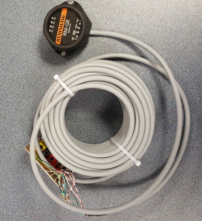
KQGRMI-QE
Mar 23, 2021RMI-QE Radio Machine Interface
Equipment Class
DSS - Part 15 Spread Spectrum Transmitter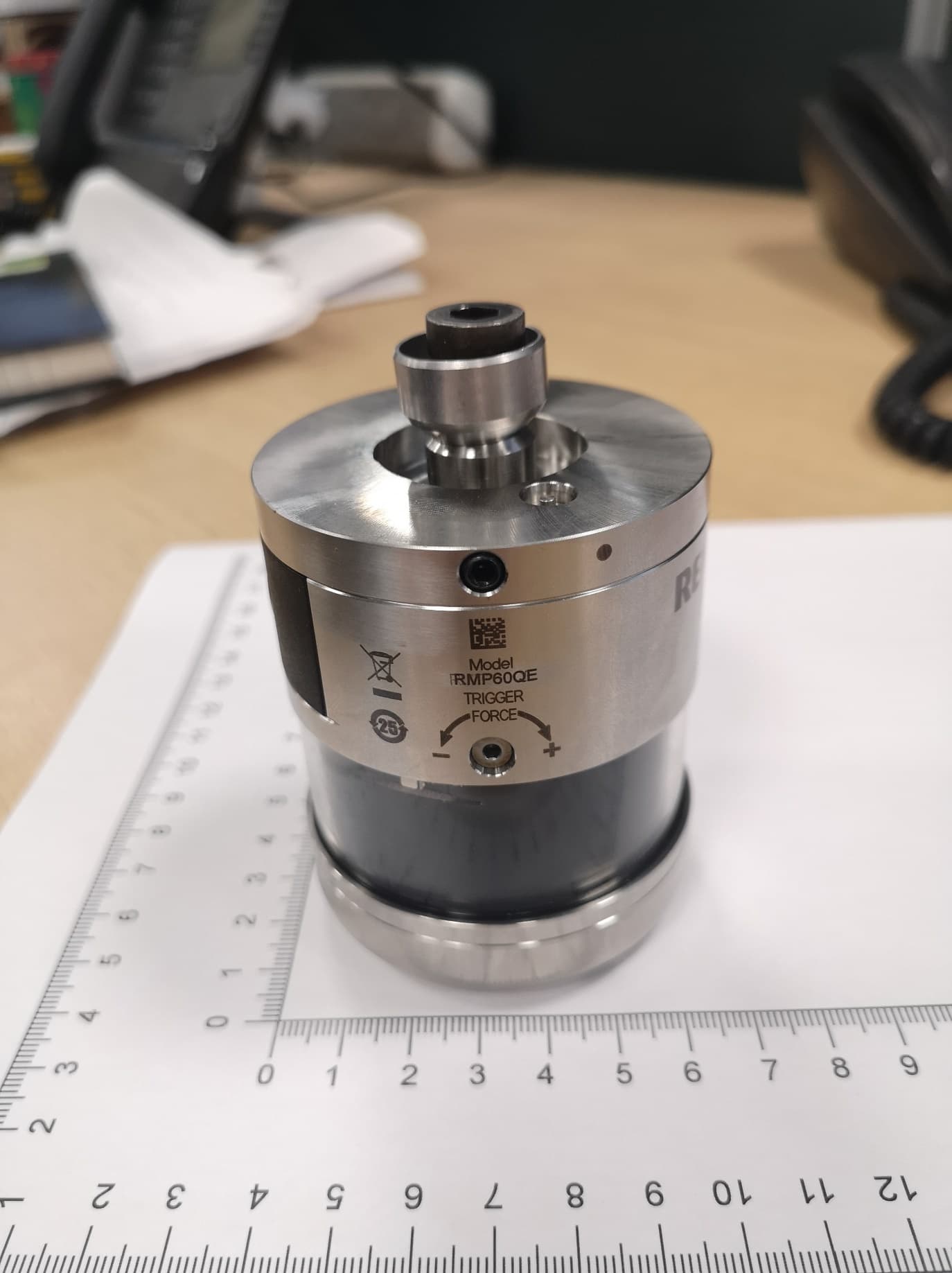
KQGRMP60QE
Apr 07, 2020Radio Machine Probe
Equipment Class
DSS - Part 15 Spread Spectrum Transmitter
KQGRTSQE
Apr 07, 2020Radio Tool Setter
Equipment Class
DSS - Part 15 Spread Spectrum Transmitter