KQGRMI-QRMI-Q Radio Machine Probe
Renishaw plc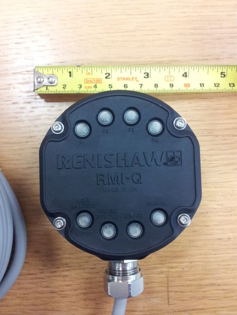
Click to zoom
Application Details
- Equipment Class
- DSS - Part 15 Spread Spectrum Transmitter
- Date of Grant
- Sep 27, 2012
- Application Purpose
- Original Equipment
- Date of Application
- Sep 27, 2012
- Equipment Note
- RMI-Q Radio Machine Probe
- Frequency Range
- 2403.00000000 - 2481.00000000
- Company
- Renishaw plc
- Country
- United Kingdom
Documents & Files
Document Text
Text extracted from the exhibit documents filed with the FCC. Open a document above to read the original.
Users Manual
RMI-Q radio machine interface Installation guide H-5687-8504-01-A (BETA SITE ONLY) Renishaw part no: H-5687-8504-01-A First issued: BETA SITE ONLY © 2012 Renishaw plc. All rights reserved. This document may not be copied or reproduced in whole or in part, or transferred to any other media or language, by any means, without the prior written permission of Renishaw plc. The publication of material within this document does not imply freedom from the patent rights of Renishaw plc. i Contents Contents Before you begin ....................................................................................................1.1 Before you begin ............................................................1.1 Disclaimer ..............................................................1.1 Trademarks .............................................................1.1 Warranty ................................................................1.1 Changes to equipment .....................................................1.1 CNC machines ...........................................................1.1 Care of the RMI-Q ........................................................1.1 RMP probe family .........................................................1.2 Patents .................................................................1.2 EC declaration of conformity ...................................................1.3 WEEE directive .............................................................1.3 FCC information to the user (USA only) ..........................................1.3 Radio approval .............................................................1.4 Radio equipment - Canadian warning statements ................................1.4 Radio approvals ..........................................................1.4 Safety ....................................................................1.5 RMI-Q basics ...........................................................................................................2.1 Introduction ................................................................2.1 Power supply ...............................................................2.1 Input voltage ripple ........................................................2.1 RMI-Q visual diagnostics ......................................................2.2 P1, P2, P3, P4 SYSTEM STATUS LEDs .......................................2.3 LOW BATTERY / START LED ...............................................2.3 PROBE STATUS LED .....................................................2.3 ERROR LED ............................................................2.3 SIGNAL LED ............................................................2.3 RMI-Q installation guide ii Contents RMI-Q inputs ...............................................................2.4 RMI-Q output waveforms ......................................................2.6 RMI-Q seated start option .....................................................2.7 Switches SW1 and SW2 ......................................................2.8 Switch SW1 output configuration .............................................2.8 Switch SW2 output configuration .............................................2.9 Remote external audible output ...............................................2.11 RMI-Q dimensions ..........................................................2.12 RMI-Q specification .........................................................2.13 System installation .................................................................................................3.1 Mounting bracket (optional) ....................................................3.1 Wiring diagram (with output groupings shown) .....................................3.2 RMP - RMI-Q partnership .....................................................3.3 To partner the RMP with the RMI-Q ...........................................3.3 To partner up to four RMPs with the RMI-Q without ReniKey .......................3.4 Partnering RMPs using ReniKey (Recommended) ...............................3.5 Removing the RMP from the RMI-Q ..........................................3.5 Changing RMP position ...................................................3.5 RMI-Q cable ...............................................................3.6 Cable sealing ............................................................3.6 Fitting flexible conduit ......................................................3.6 Screw torque values .........................................................3.7 Maintenance ............................................................................................................4.1 RMI-Q cover ...............................................................4.1 Removing the RMI-Q cover .................................................4.1 Replacing the RMI-Q cover .................................................4.2 Side exit to rear exit cable conversion ............................................4.2 Fault finding ............................................................................................................6.1 Parts list ..................................................................................................................7.1 1.1 Before you begin Disclaimer RENISHAW HAS MADE CONSIDERABLE EFFORTS TO ENSURE THE CONTENT OF THIS DOCUMENT IS CORRECT AT THE DATE OF PUBLICATION BUT MAKES NO WARRANTIES OR REPRESENTATIONS REGARDING THE CONTENT. RENISHAW EXCLUDES LIABILITY, HOWSOEVER ARISING, FOR ANY INACCURACIES IN THIS DOCUMENT. Trademarks RENISHAW and the probe symbol used in the RENISHAW logo are registered trade marks of Renishaw plc in the United Kingdom and other countries. apply innovation and names and designations of other Renishaw products and technologies are trade marks of Renishaw plc or its subsidiaries. All other brand names and product names used in this document are trade names, service marks, trademarks, or registered trademar…
Text truncated - open the document above for the full version.
Users Manual
Specification Territory EU, USA, Japan, China, Canada, Switzerland, Norway and others pending. Transmission type Frequency hopping spread spectrum radio (FHSS). Radio frequency 2400 MHz – 2483.5 MHz Operating voltage 12 Vdc to 30 Vdc Operating range Up to 15 m (49.2 ft) Weight In box including 15 m (49.2 ft) of cable 2065 g (72.84 oz) 1625 g (57.32 oz) Cable 15 m (49.2 ft) of cable standard length. Optional 30 m (98.4 ft) and 50 m (164 ft) cable assemblies are also available. Screened 16 core (each core 18 x 0.1 mm). Configuration Can be configured between side and rear exit. Probe status outputs 1. SSR (N.O/N.C, pulsed/level). 2. Driven at power supply voltage (trigger high/trigger low, pulsed/level). 3. Driven output for Fanuc high speed skip. Configurable M-code input Pulsed or level. Compatible probes RMP40/RMP40M/RLP40/RTS/RMP60 and RMP600. Probe communication Up to four probes non-simutaneously. Probe turn on Optional 0.5s. Mounting Mounting bracket to allow directional setting. Sealing IPX8 (EN/IEC60529) Storage temperature -25 °C to +70 °C (-13 °F to +158 °F) Operating temperature +5 °C to +55 °C (+41 °F to +131 °F) For the best possible application and performance support please contact Renishaw. Data sheet RMI-Q RMI-Q data sheet www.renishaw.com/rmi-q Draft 2 07/09/11 Spare parts and accessories A full range of spare parts and accessories are available. Please contact Renishaw for a full list. 75° 60° 45° 30° 15° 0° 15° 30° 45° 60° 75° 90° 75° 60° 45° 30° 15° 0° 15° 45° 60° 75° 75° 60° 45° 30° 30° 45° 60° 75° 10 (33) 15 (49) 5 (16) 5 (16) 10 (33) 15 (49) 15° 0° 15° 30° 5 (16) 10 (33) 15 (49) OPERATING AND SWITCH ON/OFF Range metres (feet) RMPRMI-Q Performance envelope Dimensions Renishaw plc New Mills, Wotton-under-Edge, Gloucestershire, GL12 8JR United Kingdom T +44 (0)1453 524524 F +44 (0)1453 524901 E [email protected] www.renishaw.com For worldwide contact details, please visit our main web site at www.renishaw.com/contact *H-5687-8200-01* RENISHAW HAS MADE CONSIDERABLE EFFORTS TO ENSURE THE CONTENT OF THIS DOCUMENT IS CORRECT AT THE DATE OF PUBLICATION BUT MAKES NO WARRANTIES OR REPRESENTATIONS REGARDING THE CONTENT. RENISHAW EXCLUDES LIABILITY, HOWSOEVER ARISING, FOR ANY INACCURACIES IN THIS DOCUMENT. © 2011 Renishaw plc. All rights reserved.Part no. H-5687-8200-01-A Issued 09.11 46 (1.81) 97 (3.82) 46 (1.81) 45 (1.77) 44 (1.73) 50 (1.97) 74 (2.91) 17.5 (0.69) dimensions mm (in) 45° 4 holes M5 x 13 deep on 80 p.c.d. When using rear exit cable, provide a Ø25 (1.0) hole in mounting for clearance Blanking plug with sealing ring. The plug and seal fit either side or rear exit cable positions. Groove for rear exit O ring seal Slot to suit M6 bolts supplied (two places) Draft 2 07/09/11
Attestation Statements
Registered office Registered number New Mills, Wotton-under-Edge, 1106260, England Gloucestershire GL12 8JR 23 August 2012 DECLARATION Frequency Hopping Pattern Derivation The RMP60 derives its hopping pattern from its own unique header. Each RMP60 is assigned a unique 32-bit ID at the time of manufacture which is used during all radio communications. This ID is also used to derive two different hopping patterns. Hopping Pattern One (used with an RMI Interface) Next Channel Number = (Current Channel Number + (Unique ID Bits 14:8) + 7) MOD 79 This provides a potential of 64 different hopping patterns. Hopping Pattern Two (used with an RMI-Q Interface) A hopping pattern derivation is used that ensures all RMP60 probes operate with a unique hopping pattern. This is achieved by dividing the 79 available channels into 3 distinct groups, and then using each bit of the unique header to swap individual hops within the groups. This is repeated in excess of 250 times. This method ensures that each unique header that is used has a corresponding unique hopping sequence (within the population). Signed by John Styles CEng MIET Principal Design Engineer
Contact Information
Applicant
Richard Warren(Product Compliance & Quality Analyst)
Test Firm
Element Materials Technology Warwick LtdStewart Barrowclough
Technical Specifications
| # | Rule Parts | Frequency Range | Power Output |
|---|---|---|---|
| 2 | 15C | 2.40 GHz - 2.48 GHz | 1.30 mW |
Other Applications from Renishaw plc
KQGRUP60QE
Mar 25, 2026The RUP60 is a radio probe capable of ultrasonic thickness measurement of parallel-sided metal components where access is restricted to a single side.
Equipment Class
DTS - Digital Transmission SystemKQGRMP400SQE
Mar 13, 2026The Renishaw RMP400S is a radio transmission probe capable of both touch trigger and scanning measurement.
Equipment Class
DSS - Part 15 Spread Spectrum Transmitter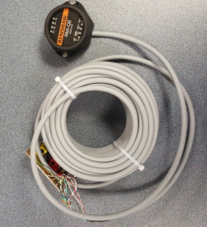
KQGRMI-QE
Mar 23, 2021RMI-QE Radio Machine Interface
Equipment Class
DSS - Part 15 Spread Spectrum Transmitter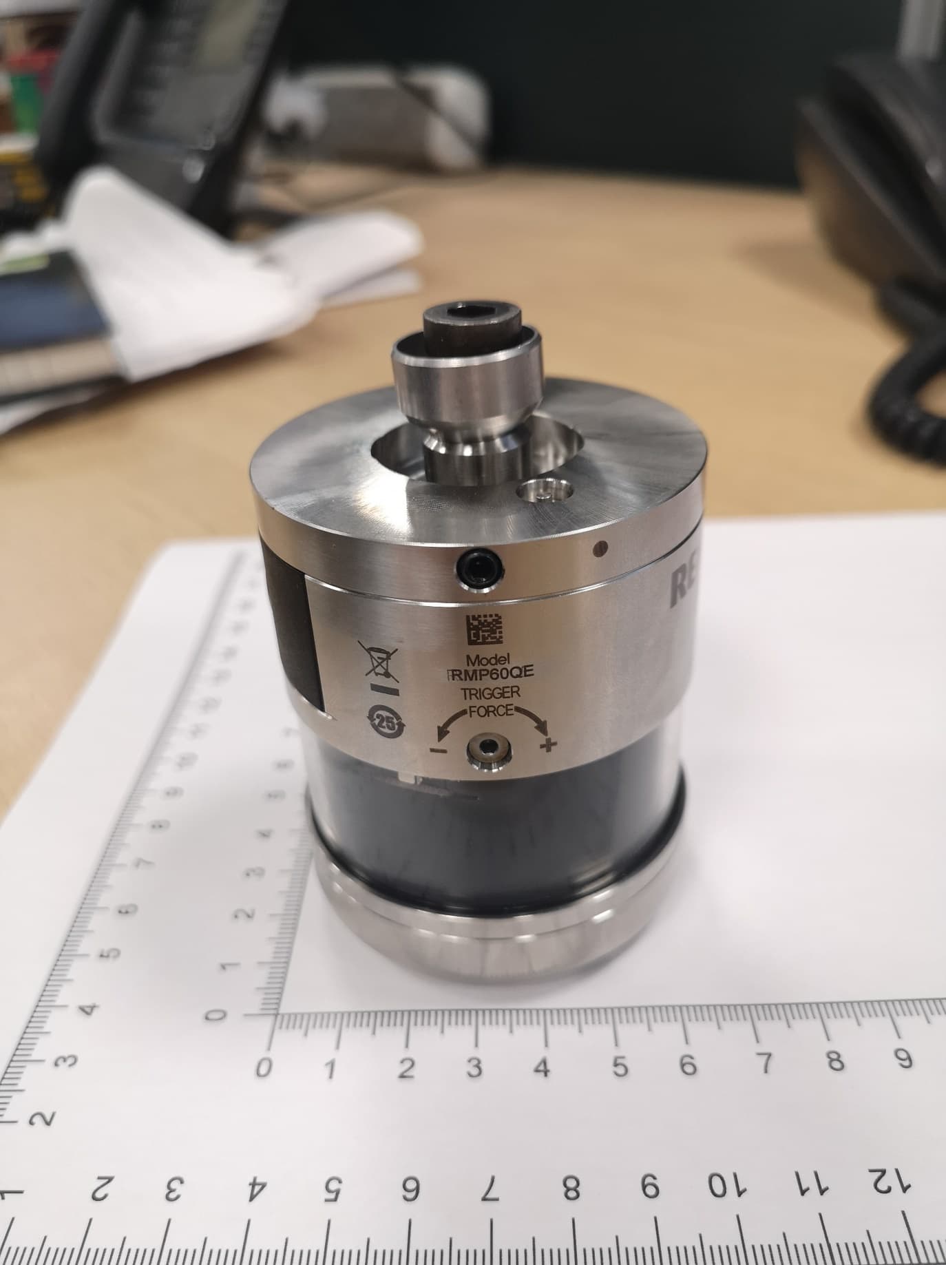
KQGRMP60QE
Apr 07, 2020Radio Machine Probe
Equipment Class
DSS - Part 15 Spread Spectrum Transmitter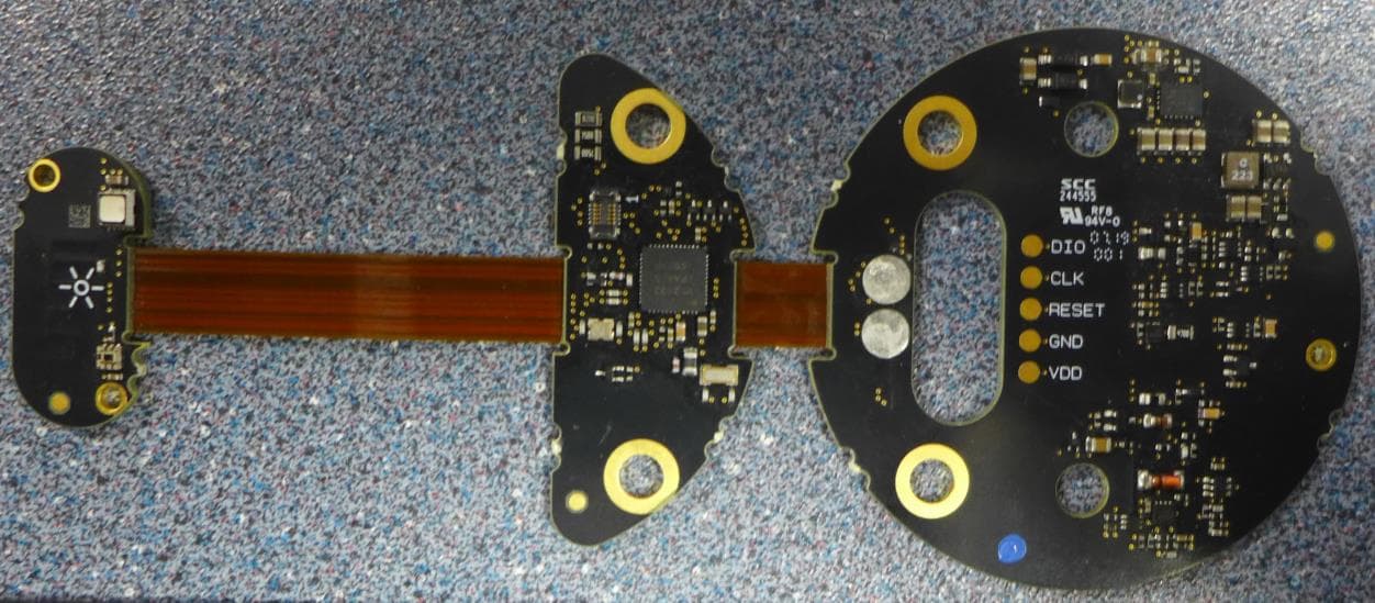
KQGRTSQE
Apr 07, 2020Radio Tool Setter
Equipment Class
DSS - Part 15 Spread Spectrum Transmitter