KQGRMP60probe for machine tools
Renishaw plc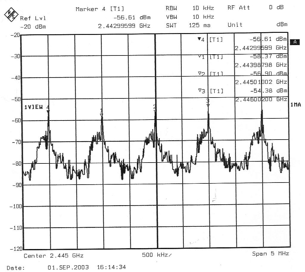
Click to zoom
Application Details
- Equipment Class
- DSS - Part 15 Spread Spectrum Transmitter
- Date of Grant
- Dec 15, 2003
- Application Purpose
- Original Equipment
- Date of Application
- Oct 16, 2003
- Equipment Note
- probe for machine tools
- Frequency Range
- 2402.00000000 - 2481.00000000
- Company
- Renishaw plc
- Country
- United Kingdom
Documents & Files
Document Text
Text extracted from the exhibit documents filed with the FCC. Open a document above to read the original.
Users Manual
Installation and user’s guideH-2000-5219-01-A RMP60 - radio probe © 2003 Renishaw. All rights reserved.Renishaw® is a registered trademarkof Renishaw plc.This document may not be copiedor reproduced in whole or in part,or transferred to any other media orlanguage, by any means, without theprior written permission of Renishaw.The publication of material within thisdocument does not imply freedomfrom the patent rights of Renishaw plc. Renishaw Part no: H-2000-5219-01-AIssued: 08.2003 DisclaimerConsiderable effort has been made to ensurethat the contents of this document are free frominaccuracies and omissions. However, Renishawmakes no warranties with respect to thecontents of this document and specificallydisclaims any implied warranties. Renishawreserves the right to make changes to thisdocument and to the product described hereinwithout obligation to notify any person of suchchanges.TrademarksAll brand names and product names used in thisdocument are trade names, service marks,trademarks, or registered trademarks of theirrespective owners. 1 EC DECLARATION OF CONFORMITY Renishaw plc declare that the product: -Name: RMP60 Description: Radio machine probe has been manufactured in conformity with the following standard: -BS EN 61326:1998/ Electrical equipment for measurement, control and laboratory use - EMC requirements.Immunity to annex A - industrial locations.Emissions to class A (non-domestic) limits. and that it complies with the requirements of directive (as amended): -89/336/EEC - Electromagnetic compatibility The above information is summarised from the full EC declaration ofconformity. A copy is available from Renishaw on request. 2WarrantyEquipment requiring attention under warrantymust be returned to your supplier. No claimswill be considered where Renishaw equipmenthas been misused, or repairs or adjustmentshave been attempted by unauthorised persons.Changes to equipmentRenishaw reserves the right to changespecifications without notice.CNC machineCNC machine tools must always be operatedby competent persons in accordance withmanufacturers instructions.Installation and user’s guide Care of the probeKeep system components clean and treat theprobe as a precision tool.Patent noticeFeatures of products shown in this guide,and of related products, are the subject of thefollowing patents and/or patent applications:EP 0652413 US 4599524 US 5,279,042 JP 3,126,797 WO 02/063235WO 03/021182 Installation and user’s guide 3 Contents Typical probe system with radiotransmission .................................................... 4 System performance ...................................... 5 Operating envelope ........ ................................. 6 RMP60 features .............................................. 7 RMP60 specification ....................................... 8 Probe status LED ............................................ 9 Weak link stem ................................................ 9 Modes of operation ....................................... 10 Reviewing current probe settings ................ 12 Configuration using trigger logic ................... 13 System setup/establishingRMP60/RMI partnership ............................... 15 RMP60 batteries ........................................... 17 Battery life expectancy ................................. 19 RMP60/shank mounting ............................... 21 Stylus on-centre adjustment ......................... 22 Stylus trigger force adjustment ..................... 23Probe moves ................................................. 24Software requirements .................................. 26 Typical probe cycles ..................................... 27 Diaphr agm replacement ................................ 29 Fault finding .................................................... 31 Appendix 1 RMI ........................................... 36 Parts list ......................................................... 38 Contents 4Typical probe system with radio transmission A workpiece set-up and inspection probeis in effect another tool in the system.A probing cycle may be included at anystage of the machining process. Typical probe system with radio transmission CNC machining centre spindle Typical tool setting probe C N C machine control Optional - PSU3 power supply unit RMI mounting bracket Interface unit Cable Optional - PSU3 power supply unit Workpiece RMI Interface Probe data signals are transmitted via radio linkto the RMI and on to the machine control. TheRMI converts probe signals into an acceptableform for the machine control. RMP60 inspection probe Stylus Probe status LEDs 5 Operating envelopeSurfaces within the machine may increase thesignal transmission range.Coolant and swarf residue accumulating on theRMP60 and RMI may have a detrimental effecton transmission performance. Wipe clean asoften as is necessary to maintain unrestrictedtransmission.When operating, do not touch with your hand,either the RMI cover or the probe glass window,as this will change the performance.Operation in extremes of temperature will resultin some reduction in range.RMI positionTo assist finding the optimum position of the RMIduring system installation, a signal strengthindication LED is available on the RMI interface.RMI signal strength is displayed on an RMImulti-coloured LED.System performance System performance Environment RMP60 RMI PSU3 Storage Normal operating Temperature -10 °C to 70 °C (14 °F to 158 °F) 5 °C to 50 °C (41 F° to 122 °F) Probe repeatabilityMaximum 2 Sigma (2 V ) Value Repeatability of 1,0 μm (40 μ in) is valid fortest velocity of 480 mm/min (1.57 ft/min) atstylus tip, using stylus 50 mm (1.97 in) long. 6 Operating envelope Operating envelope RMP60 probe + RMIRMP60 and RMI must be within each othersoperating envelope shown. Range metres (feet) OPERATING AND SWITCH ON/OFF 90° 75° 60° 45° 30° 15° 0° 15° 30° 45° 60° 75° 90° 75° 60° 45° 30° 15° 0° 15° 45° 60° 75° 75° 60° 45° 30° 30° 45° 60° 75° 10 (33) 15 (49) 5 (16) 5 (16) …
Text truncated - open the document above for the full version.
Block Diagram
1 abcdefg COMPANY CONFIDENTIAL PAGE 1 OF 4 Document No: PD- 4113 – 9058Issue: draft ADate: 25 September 2003 Document Title: RMP60 system description and functional block diagrams. Summary/Scope: This document provides a description and block diagram as required by FCC regulations. Reason for Issue/Nature of change: Distribution: Author:Job Title:Signed:Date: M Woollett Radio Group Leader Reviewed by:Job Title:Signed:Date: S Cresson Design Engineer Ren Sa Reviewed by:Job Title:Signed:Date: Approved by:Job Title:Signed:Date: Form No: QA401Issue: 1Date: 10 Aug 93 2 Summary of RMP60 system RMP60 is a point to point touch trigger probe radio transmission system for use on CNC (computer numerically controlled) machine tools. It consists of two components, the RMP (Radio Module Probe) and RMI (Radio Machine Interface) which are the two radio stations. Radio details RMP60 uses FHSS (frequency hopping spread spectrum) transmission in the frequency band from 2402 to 2480 MHz. There are 79 * 1 MHz wide channels. The maximum ERP (emitted radio power) is 1mw (0dBm) and the transmission range is up to 15m. The radio link is bi-directional with half duplex transmission. Both RMP and RMI use a PB31301 Ericsson radio modem. This is a transceiver circuit. When transmitting the modem uses a synthesiser to generate the desired carrier from the 13MHz clock. The modem then modulates this carrier using the input serial data and then amplifies it for transmission to the antenna via a filter. When receiving the signal from the antenna is fed via the filter to a low noise amplifier and then to the built in heterodyne receiver. The synthesiser makes a local oscillator 3MHz below the carrier signal. Following a mixer the signal is demodulated and the resulting serial received data is output . RMP (see Fig 1) The RMP is 63mm diameter, and 76mm long, and has a standard mounting face for fitment to a machine tool shank on one end and a M4 stylus mount on the other. The RMP contains a touch trigger probe similar to the Renishaw MP7 probe module. The RMP is battery powered by 2* AA batteries, the total voltage of which must be between 2V and 7.2V. The RMP contains the electronic circuitry needed to process the probe signals and convert them into radio transmissions. The RMP is controlled by a microprocessor. The microprocessor encodes and decodes the radio messages that are sent or received via the FPGA to or from the radio modem. The FPGA contains a correlator which is used to recognise messages addressed to the RMP. The FPGA contains the timing logic required for the radio modem. The microprocessor and the FPGA use the 4Mhz clock. There is a radio standby mode of operation during which most of the circuitry is switched off and only the microprocessor runs continuously using the 32768Hz clock. RMI (see Fig 2) The RMI dimensions are 94*97*44mm (L*W*H), with a cable exit gland which can be fitted to its side or rear faces. The RMI is intended to be connected to the machine tool controller using a multicore screened cable supplied with the RMI. The RMI is powered from the machine tool by 10-30V DC. The RMI contains the electronic circuitry needed to process the radio transmissions to and from the RMP, and the inputs and outputs to and from the machine tools CNC controller. The RMI is controlled by a microprocessor. The microprocessor encodes and decodes the radio messages that are sent or received via the FPGA to or from the radio modem. The FPGA contains a correlator which is used to recognise messages addressed to the RMI. The FPGA contains the timing logic required for the radio modem. The microprocessor and the FPGA use the 40Mhz clock. The RMI outputs to the machine tool include 3 * solid state relay outputs (probe status/ skip, low battery and error) and 1 driven output (for probe status/ skip). The RMI has an input for an M code start for the system. 3 Fig 1 RMP60 Functional Block Diagram Radio Modem Baseband Processor/ PIC Shank Switch Connections & Interface Antenna Probe Sensor & Interface FPGA Buffer, Correlator & Timing Logic 13 MHz Clock Power Supply (switch mode) Batteries 2.0V – 7.2V DC 4 MHz Clock32768Hz Clock Spin Switch Sensor & Interface Status Led (3 off Red/ Green/ Blue) 4 Fig 2 RMI Functional block diagram Radio ModemBaseband Processor/ PIC Start input AntennaElectrical outputs, SSRs & driven. FPGA Buffer, Correlator & Timing Logic 13 MHz Clock Power Supply (switch mode) Power input 10-30V DC 40 MHz Clock User indicator leds, signal str, error, probe status & low batt
External Photos
EMITECH ATLANTIQUE 15, rue de la Claie Z.I. Angers-Beaucouzé 49070 BEAUCOUZÉ Tél. 02 41 73 26 27 Fax 02 41 73 26 40 e-mail : [email protected] R.C.S. ANGERS 95 B 543 SIRET 344 545 645 00055 SIEGE SOCIAL : EMITECH S.A. 3, rue des Coudriers – Z.A. de l’Observatoire – 78180 MONTIGNY-LE-BRETONNEUX – Tél. 01 30 57 55 55 – Fax 01 30 43 74 48 S.A. AU CAPITAL DE 480 000 € - R.C. VERSAILLES B 344 545 645 – SIRET 344 545 645 000 22 – CODE APE 742 C RA-03-24216/A/ST FCC CERTIFICATION E.M.C. Measurement Technical Report standard to apply: FCC Part 15 Equipment under test: PROBE FOR MACHINE TOOLS RMP60 FCC ID: KQGRMP60 Company: RENISHAW SA TRANSMIT TO: Mr CRESSON Company: RENISHAW SA Number of pages: 11 + 4 appendixes Verification Ed. Date ModifiedEditing Approval pages Name Visa Name Visa 0 29-Sep-03 Creation D. GRATON Duplication of this test report is only permitted for an integral photographic facsimile. It includes the number of pages referenced here above. This document is the result of testing a specimen or a sample of the product submitted. It does not imply an assessment of the conformity of the whole manufactured products of the tested sample. EMITECH ATLANTIQUE RA-03-24216 DATE: 29-Sep-03 PAGE: 2 / 11 RIA-03-24216-A PRODUCT: PROBE FOR MACHINE TOOLS Reference / model : RMP60 Serial number: Y68723 MANUFACTURER: RENISHAW PLC New Mills, Wotten Under Edge GLOUCESTERSHIRE GL12 8JR UNITED KINGDOM COMPANY SUBMITTING THE PRODUCT: Company : RENISHAW SA Address: 15, rue Albert Einstein 77437 MARNE LA VALLEE CEDEX 2 FRANCE Responsible : Mr CRESSON DATE(S) OF TEST: 01 and 02 September 2003 TESTING LOCATION: EMITECH ATLANTIQUE laboratory at ANGERS (49) FRANCE EMITECH ATLANTIQUE open area test site in LA POUEZE (49) FRANCE EMITECH laboratory at MONTIGNY LE BRETONNEUX (78) FRANCE Registration Number by FCC: 101696/FRN: 0006 6490 08 Registration Number by Industry Canada: IC4379 TESTED BY: D. GRATON P. BONNENFANT EMITECH ATLANTIQUE RA-03-24216 DATE: 29-Sep-03 PAGE: 3 / 11 RIA-03-24216-A CONTENTS TITLE PAGE 1. INTRODUCTION.......................................................................................................................... 4 2. PRODUCT DESCRIPTION .........................................................................................................4 3. NORMATIVE REFERENCE....................................................................................................... 4 4. TEST METHODOLOGY .............................................................................................................5 5. RELATED SUBMITTAL GRANT .............................................................................................. 5 6. ADD ATTACHMENTS FILES .................................................................................................... 5 7. TESTS AND CONCLUSIONS ..................................................................................................... 6 8. PEAK OUTPUT POWER............................................................................................................. 7 9. RADIATED EMISSION PORTABLE ........................................................................................ 9 10. APPENDIXES ............................................................................................................................ 11 APPENDIX 1: SCHANNEL SEPARATIONT........................................................................... 11 APPENDIX 2: S TIMING HOPPING AND TIMING CHANNELT......................................... 11 APPENDIX 3: SPHOTOGRAPHIES OF THE EQUIPEMENT UNDER TESTT.................... 11 APPENDIX 4: SPHOTOGRAPHY OPEN AREA TEST SITET............................................... 11 EMITECH ATLANTIQUE RA-03-24216 DATE: 29-Sep-03 PAGE: 4 / 11 RIA-03-24216-A 1.INTRODUCTION This document presents the result of E.M.C. test carried out on the following equipment: PROBE FOR MACHINE TOOLS RMP60 in accordance with normative reference. 2.PRODUCT DESCRIPTION ITU Emission code: 1M00F7D Classe: A (paragraph FCC part 15.3) Utilization: radio probe for machine tools. Antenna type: incorporated antenna Operating frequency range: from 2400 MHz to 2483.5 MHz Number of channels: 80 Channel spacing: 1 MHz Frequency generation: | SAW Resonator | Crystal ~ Synthetiser Modulation: Frequency Hopping Spread Spectrum | Amplitude | Digital ~ Frequency | Phase Power source: batteries power (2 x 1.5 VAA alcaline type) or (2 x 3.6 VAA lithium type) Power level, frequency range and channels characteristics are not user adjustable. The details pictures of the product, the circuit boards and antennas are joined with this file. 3.NORMATIVE REFERENCE FCC Part 15 (2003) Code of Federal Regulations Title 47 - Telecommunication Chapter 1 - Federal Communications Commission Part 15 - Radio frequency devices Subpart C - Intentional Radiators RSS 210 Low Power Licence - Exempt Radiocommunication Devices (All Frequency Bands) EMITECH ATLANTIQUE RA-03-24216 DATE: 29-Sep-03 PAGE: 5 / 11 RIA-03-24216-A 4.TEST METHODOLOGY Radio performance tests procedures given in part 15: Paragraph 33: frequency range of radiated measurements Paragraph 35: measurement detector functions and bandwidths Paragraph 207: conducted limits Paragraph 205: restricted bands of operation Paragraph 209: radiated emission limits; general requirements Paragraph 247: operation within the band 2400 – 2483.5 MHz 5.RELATED SUBMITTAL GRANT This equipment operates with an radio interface for machine tools, RMI: KQGRMI. 6.ADD ATTACHMENTS FILES SSynopticS SBlock diagramS SExternal photos and Product labelingS SAssembly of componentsS SInternal photosS SLayout pcbS SBil of materialsS SSchematicsS SProduct descriptionS SUser guideS EMITECH ATLANTIQUE RA-03-24216 DATE: 29-Sep-03 PAGE: 6 / 11 RIA-03-24216-A 7.TESTS AND CONCLUSIONS Test Description of test Criteria respected ? Comment procedure Yes No NAp NAs FCC Part 15.205 RESTRICTED BANDS OF OPERATION X FCC Part 15.207 CONDUCTED LIMITS X Note 4 FCC Part 15.2…
Text truncated - open the document above for the full version.
Operational Description
1 abcdefg COMPANY CONFIDENTIAL PAGE 1 OF 4 Document No: PD- 4113 – 9058Issue: draft ADate: 25 September 2003 Document Title: RMP60 system description and functional block diagrams. Summary/Scope: This document provides a description and block diagram as required by FCC regulations. Reason for Issue/Nature of change: Distribution: Author:Job Title:Signed:Date: M Woollett Radio Group Leader Reviewed by:Job Title:Signed:Date: S Cresson Design Engineer Ren Sa Reviewed by:Job Title:Signed:Date: Approved by:Job Title:Signed:Date: Form No: QA401Issue: 1Date: 10 Aug 93 2 Summary of RMP60 system RMP60 is a point to point touch trigger probe radio transmission system for use on CNC (computer numerically controlled) machine tools. It consists of two components, the RMP (Radio Module Probe) and RMI (Radio Machine Interface) which are the two radio stations. Radio details RMP60 uses FHSS (frequency hopping spread spectrum) transmission in the frequency band from 2402 to 2480 MHz. There are 79 * 1 MHz wide channels. The maximum ERP (emitted radio power) is 1mw (0dBm) and the transmission range is up to 15m. The radio link is bi-directional with half duplex transmission. Both RMP and RMI use a PB31301 Ericsson radio modem. This is a transceiver circuit. When transmitting the modem uses a synthesiser to generate the desired carrier from the 13MHz clock. The modem then modulates this carrier using the input serial data and then amplifies it for transmission to the antenna via a filter. When receiving the signal from the antenna is fed via the filter to a low noise amplifier and then to the built in heterodyne receiver. The synthesiser makes a local oscillator 3MHz below the carrier signal. Following a mixer the signal is demodulated and the resulting serial received data is output . RMP (see Fig 1) The RMP is 63mm diameter, and 76mm long, and has a standard mounting face for fitment to a machine tool shank on one end and a M4 stylus mount on the other. The RMP contains a touch trigger probe similar to the Renishaw MP7 probe module. The RMP is battery powered by 2* AA batteries, the total voltage of which must be between 2V and 7.2V. The RMP contains the electronic circuitry needed to process the probe signals and convert them into radio transmissions. The RMP is controlled by a microprocessor. The microprocessor encodes and decodes the radio messages that are sent or received via the FPGA to or from the radio modem. The FPGA contains a correlator which is used to recognise messages addressed to the RMP. The FPGA contains the timing logic required for the radio modem. The microprocessor and the FPGA use the 4Mhz clock. There is a radio standby mode of operation during which most of the circuitry is switched off and only the microprocessor runs continuously using the 32768Hz clock. RMI (see Fig 2) The RMI dimensions are 94*97*44mm (L*W*H), with a cable exit gland which can be fitted to its side or rear faces. The RMI is intended to be connected to the machine tool controller using a multicore screened cable supplied with the RMI. The RMI is powered from the machine tool by 10-30V DC. The RMI contains the electronic circuitry needed to process the radio transmissions to and from the RMP, and the inputs and outputs to and from the machine tools CNC controller. The RMI is controlled by a microprocessor. The microprocessor encodes and decodes the radio messages that are sent or received via the FPGA to or from the radio modem. The FPGA contains a correlator which is used to recognise messages addressed to the RMI. The FPGA contains the timing logic required for the radio modem. The microprocessor and the FPGA use the 40Mhz clock. The RMI outputs to the machine tool include 3 * solid state relay outputs (probe status/ skip, low battery and error) and 1 driven output (for probe status/ skip). The RMI has an input for an M code start for the system. 3 Fig 1 RMP60 Functional Block Diagram Radio Modem Baseband Processor/ PIC Shank Switch Connections & Interface Antenna Probe Sensor & Interface FPGA Buffer, Correlator & Timing Logic 13 MHz Clock Power Supply (switch mode) Batteries 2.0V – 7.2V DC 4 MHz Clock32768Hz Clock Spin Switch Sensor & Interface Status Led (3 off Red/ Green/ Blue) 4 Fig 2 RMI Functional block diagram Radio ModemBaseband Processor/ PIC Start input AntennaElectrical outputs, SSRs & driven. FPGA Buffer, Correlator & Timing Logic 13 MHz Clock Power Supply (switch mode) Power input 10-30V DC 40 MHz Clock User indicator leds, signal str, error, probe status & low batt
Parts List/Tune Up Info
FRAME PARTS LIST A-4113-0500-04-A TITLE: RMP60 FLEXI Compiled By: dh1015 Date: 24-Jun-2003 Issue Number: FIN 919 Serial Number: NO Sheet Number: 1 of 2 Item Part Number Part Description Qty Reference 1 M-4113-0501-06 RMP60 FLEXI 1 2 3 4 5 6 7 8 A-4113-0950-01 SM EX256 PQ100 8K FPGA 1 IC2 9 M-4038-0550-01 G-FORCE SWITCH 1 SW1 10 P-CP14-33P1 SM CAP 33pF 0603 5% NPO 50V 5 C2,C3,C4, C5,C14 11 P-CP16-1M00 SM CAP 1u A 10% TANT 16V 1 C29 12 P-CP16-22M0 SM CAP 22u D 10% TANT 20V 1 C32 13 P-CP16-2M22 SM CAP 22u B 20% TANT 16V 5 C31,C33,C34, C35,C36 14 P-CP22-18P0 SM CAP COG 18pF 50V +/-5% 1 C13 15 P-CP22-22N0 SM CAP 22N 0603 X7R 10% 13 C1,C6,C12, C15,C16,C17, C18,C19,C20, C21,C22,C23, C25 16 P-CP22-N101 SM CAP 100P 0603 COG 5% 3 C26,C27,C28 17 P-CT04-0010 SM CRYSTAL CERAMIC 13.00MHz 1 XT3 18 P-CT04-0011 SMD WATCH CRYSTAL 32.768KHz 1 XT1 19 P-CT04-0012 SM XTAL 4.0MHz 50ppm 32SMX 1 XT2 20 P-DD08-0003 SM DIODE SCHOTTY 40V 1.0A 3 D1,D2,D3 21 P-FT03-0005 SM Trans Supp 14V 40A 1206 4 VDR1,VDR2,VDR3, VDR4 22 P-LX02-0019 SM INDUCTOR FIX 22uH 0.45A 3 L1,L2,L3 23 P-MB01-0001 SM 2.4GHz RF TRANSCEIVER 1 IC8 24 P-MC05-0001 DUAL INPUT AND GATE 1 IC4 25 P-ML04-0923 SM MAX923 COMP DUAL ULP 1 IC1 26 P-MP10-0027 SM LP 8BIT 4-10MHz PIC16LF877 1 IC3 27 P-MR01-0005 SM XC62FP VOLT REG +2.8V 0.25A 1 VR4 28 P-MR01-0006 SM XC62H VOLT REG +2.5V 0.165A 1 VR3 29 P-MR05-0005 SM XC6366 SWIT REG+ADJ 1A 1 VR5 30 P-MR05-0006 SM XC6368 SWIT REG+ADJ 0.2A 2 VR1,VR2 31 P-MR09-0001 SM XC61C V DETECT 3.3V 0.7uA 1 IC5 32 P-MR09-0002 SM XC61F V DETECT 2.5V 1.0uA 1 IC6 33 P-RF35-010K SMRES 10K 0603 1% 100ppm 50V 5 R1,R5,R22, R27,R34 34 P-RF35-01K5 SMRES 1K5 0603 1% 100ppm 50V 1 R30 35 P-RF35-01M0 SMRES 1M0 0603 1% 100ppm 50V 16 R4,R16,R17, R18,R20,R21, R23,R24,R26, R29,R35,R41, R46,R47,R48, R49 36 P-RF35-02M2 SMRES 2M2 0603 1% 100ppm 50V 1 R36 37 P-RF35-03K3 SMRES 3K3 0603 1% 100ppm 50V 3 R8,R11,R14 FRAME PARTS LIST A-4113-0500-04-A TITLE: RMP60 FLEXI Compiled By: dh1015 Date: 24-Jun-2003 Issue Number: FIN 919 Serial Number: NO Sheet Number: 2 of 2 Item Part Number Part Description Qty Reference 38 P-RF35-03K6 SMRES 3K6 0603 1% 100ppm 50V 3 R7,R10,R13 39 P-RF35-047K SMRES 47K 0603 1% 100ppm 50V 2 R31,R37 40 P-RF35-04K7 SMRES 4K7 0603 1% 100ppm 50V 1 R28 41 P-RF35-06K8 SMRES 6K8 0603 1% 100ppm 50V 3 R9,R12,R15 42 P-RF35-100K SMRES 100K 0603 1% 100ppm 50V 2 R25,R42 43 P-RF35-470K SMRES 470K 0603 1% 100ppm 50V 1 R43 44 P-RF35-510K SMRES 510K 0603 1% 100ppm 50V 1 R44 45 P-RF35-560K SMRES 560K 0603 1% 100ppm 50V 1 R33 46 P-RF35-820K SMRES 820K 0603 1% 100ppm 50V 1 R45 47 P-RF38-10R0 SMRES 10R mMELF 1% 50ppm 200V 1 R19 48 P-TR03-0005 SM P-FET FDN358P -30V -1.5A 4 TR1,TR2,TR3, TR15 49 P-TR03-335N SM N-FET FDN335N 20V 1.7A 11 TR4,TR5,TR6, TR7,TR8,TR9, TR10,TR11,TR12, TR13,TR14 50 P-VT01-0003 SM LED RED/GRN/BLUE 20mA 120 D 3 D4,D5,D6 51 C-4113-0500-04 CIRCUIT DIAGRAM REF 52 D-4113-0508-05 TEST POINT DRAWING REF 53 T80264-04 PASTE TOOL REF 54 4113-050004a GENCAD REF
Test Report
EMITECH ATLANTIQUE 15, rue de la Claie Z.I. Angers-Beaucouzé 49070 BEAUCOUZÉ Tél. 02 41 73 26 27 Fax 02 41 73 26 40 e-mail : [email protected] R.C.S. ANGERS 95 B 543 SIRET 344 545 645 00055 SIEGE SOCIAL : EMITECH S.A. 3, rue des Coudriers – Z.A. de l’Observatoire – 78180 MONTIGNY-LE-BRETONNEUX – Tél. 01 30 57 55 55 – Fax 01 30 43 74 48 S.A. AU CAPITAL DE 480 000 € - R.C. VERSAILLES B 344 545 645 – SIRET 344 545 645 000 22 – CODE APE 742 C RA-03-24216/A/ST FCC CERTIFICATION E.M.C. Measurement Technical Report standard to apply: FCC Part 15 Equipment under test: PROBE FOR MACHINE TOOLS RMP60 FCC ID: KQGRMP60 Company: RENISHAW SA TRANSMIT TO: Mr CRESSON Company: RENISHAW SA Number of pages: 11 + 4 appendixes Verification Ed. Date ModifiedEditing Approval pages Name Visa Name Visa 0 29-Sep-03 Creation D. GRATON Duplication of this test report is only permitted for an integral photographic facsimile. It includes the number of pages referenced here above. This document is the result of testing a specimen or a sample of the product submitted. It does not imply an assessment of the conformity of the whole manufactured products of the tested sample. EMITECH ATLANTIQUE RA-03-24216 DATE: 29-Sep-03 PAGE: 2 / 11 RIA-03-24216-A PRODUCT: PROBE FOR MACHINE TOOLS Reference / model : RMP60 Serial number: Y68723 MANUFACTURER: RENISHAW PLC New Mills, Wotten Under Edge GLOUCESTERSHIRE GL12 8JR UNITED KINGDOM COMPANY SUBMITTING THE PRODUCT: Company : RENISHAW SA Address: 15, rue Albert Einstein 77437 MARNE LA VALLEE CEDEX 2 FRANCE Responsible : Mr CRESSON DATE(S) OF TEST: 01 and 02 September 2003 TESTING LOCATION: EMITECH ATLANTIQUE laboratory at ANGERS (49) FRANCE EMITECH ATLANTIQUE open area test site in LA POUEZE (49) FRANCE EMITECH laboratory at MONTIGNY LE BRETONNEUX (78) FRANCE Registration Number by FCC: 101696/FRN: 0006 6490 08 Registration Number by Industry Canada: IC4379 TESTED BY: D. GRATON P. BONNENFANT EMITECH ATLANTIQUE RA-03-24216 DATE: 29-Sep-03 PAGE: 3 / 11 RIA-03-24216-A CONTENTS TITLE PAGE 1. INTRODUCTION.......................................................................................................................... 4 2. PRODUCT DESCRIPTION .........................................................................................................4 3. NORMATIVE REFERENCE....................................................................................................... 4 4. TEST METHODOLOGY .............................................................................................................5 5. RELATED SUBMITTAL GRANT .............................................................................................. 5 6. ADD ATTACHMENTS FILES .................................................................................................... 5 7. TESTS AND CONCLUSIONS ..................................................................................................... 6 8. PEAK OUTPUT POWER............................................................................................................. 7 9. RADIATED EMISSION PORTABLE ........................................................................................ 9 10. APPENDIXES ............................................................................................................................ 11 APPENDIX 1: SCHANNEL SEPARATIONT........................................................................... 11 APPENDIX 2: S TIMING HOPPING AND TIMING CHANNELT......................................... 11 APPENDIX 3: SPHOTOGRAPHIES OF THE EQUIPEMENT UNDER TESTT.................... 11 APPENDIX 4: SPHOTOGRAPHY OPEN AREA TEST SITET............................................... 11 EMITECH ATLANTIQUE RA-03-24216 DATE: 29-Sep-03 PAGE: 4 / 11 RIA-03-24216-A 1.INTRODUCTION This document presents the result of E.M.C. test carried out on the following equipment: PROBE FOR MACHINE TOOLS RMP60 in accordance with normative reference. 2.PRODUCT DESCRIPTION ITU Emission code: 1M00F7D Classe: A (paragraph FCC part 15.3) Utilization: radio probe for machine tools. Antenna type: incorporated antenna Operating frequency range: from 2400 MHz to 2483.5 MHz Number of channels: 80 Channel spacing: 1 MHz Frequency generation: | SAW Resonator | Crystal ~ Synthetiser Modulation: Frequency Hopping Spread Spectrum | Amplitude | Digital ~ Frequency | Phase Power source: batteries power (2 x 1.5 VAA alcaline type) or (2 x 3.6 VAA lithium type) Power level, frequency range and channels characteristics are not user adjustable. The details pictures of the product, the circuit boards and antennas are joined with this file. 3.NORMATIVE REFERENCE FCC Part 15 (2003) Code of Federal Regulations Title 47 - Telecommunication Chapter 1 - Federal Communications Commission Part 15 - Radio frequency devices Subpart C - Intentional Radiators RSS 210 Low Power Licence - Exempt Radiocommunication Devices (All Frequency Bands) EMITECH ATLANTIQUE RA-03-24216 DATE: 29-Sep-03 PAGE: 5 / 11 RIA-03-24216-A 4.TEST METHODOLOGY Radio performance tests procedures given in part 15: Paragraph 33: frequency range of radiated measurements Paragraph 35: measurement detector functions and bandwidths Paragraph 207: conducted limits Paragraph 205: restricted bands of operation Paragraph 209: radiated emission limits; general requirements Paragraph 247: operation within the band 2400 – 2483.5 MHz 5.RELATED SUBMITTAL GRANT This equipment operates with an radio interface for machine tools, RMI: KQGRMI. 6.ADD ATTACHMENTS FILES SSynopticS SBlock diagramS SExternal photos and Product labelingS SAssembly of componentsS SInternal photosS SLayout pcbS SBil of materialsS SSchematicsS SProduct descriptionS SUser guideS EMITECH ATLANTIQUE RA-03-24216 DATE: 29-Sep-03 PAGE: 6 / 11 RIA-03-24216-A 7.TESTS AND CONCLUSIONS Test Description of test Criteria respected ? Comment procedure Yes No NAp NAs FCC Part 15.205 RESTRICTED BANDS OF OPERATION X FCC Part 15.207 …
Text truncated - open the document above for the full version.
Contact Information
Applicant
Richard Warren(Product Compliance & Quality Analyst)
Technical Contact
RENISHAWSERGE CRESSON
[email protected]33 1 64 61 84 84
15, RUE ALBERT EINSTEIN · MARNE LA VALLEE · France
Test Firm
EMITECH AngersOliver Roy
Technical Specifications
| # | Rule Parts | Frequency Range | Power Output |
|---|---|---|---|
| 1 | 15C | 2.40 GHz - 2.48 GHz | 1.50 mW |
Other Applications from Renishaw plc
KQGRUP60QE
Mar 25, 2026The RUP60 is a radio probe capable of ultrasonic thickness measurement of parallel-sided metal components where access is restricted to a single side.
Equipment Class
DTS - Digital Transmission SystemKQGRMP400SQE
Mar 13, 2026The Renishaw RMP400S is a radio transmission probe capable of both touch trigger and scanning measurement.
Equipment Class
DSS - Part 15 Spread Spectrum Transmitter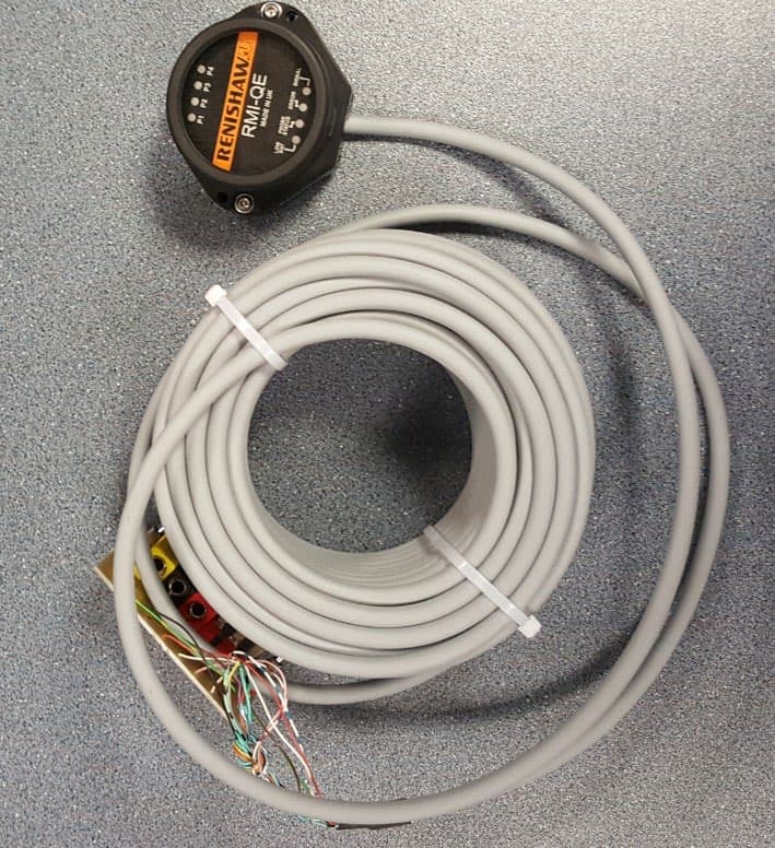
KQGRMI-QE
Mar 23, 2021RMI-QE Radio Machine Interface
Equipment Class
DSS - Part 15 Spread Spectrum Transmitter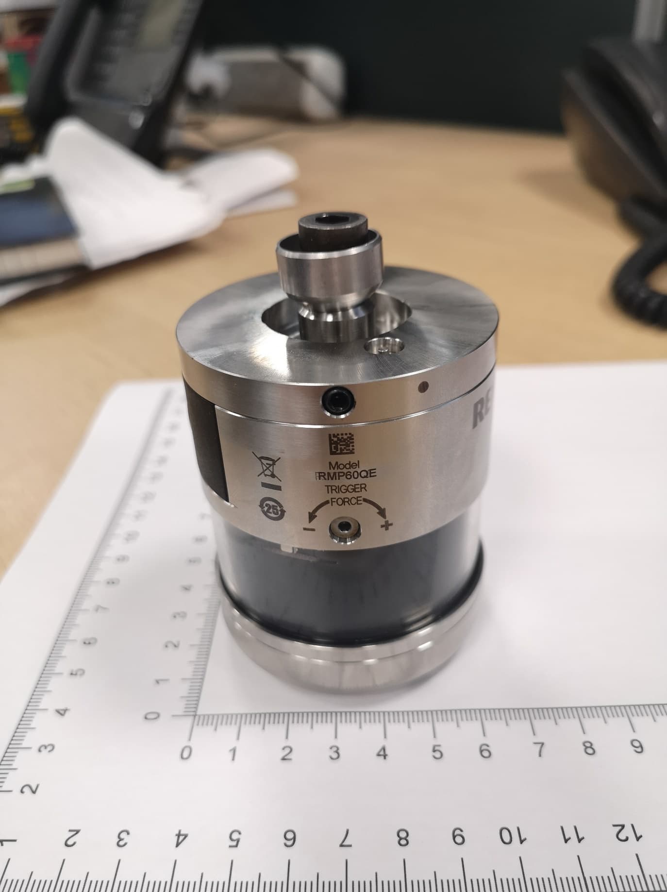
KQGRMP60QE
Apr 07, 2020Radio Machine Probe
Equipment Class
DSS - Part 15 Spread Spectrum Transmitter
KQGRTSQE
Apr 07, 2020Radio Tool Setter
Equipment Class
DSS - Part 15 Spread Spectrum Transmitter