KQGRMP60QRMP60 Radio Machine Probe
Renishaw plc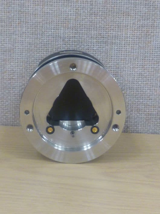
Click to zoom
Application Details
- Equipment Class
- DSS - Part 15 Spread Spectrum Transmitter
- Date of Grant
- Sep 09, 2012
- Application Purpose
- Original Equipment
- Date of Application
- Sep 09, 2012
- Equipment Note
- RMP60 Radio Machine Probe
- Frequency Range
- 2403.00000000 - 2481.00000000
- Company
- Renishaw plc
- Country
- United Kingdom
Documents & Files
Document Text
Text extracted from the exhibit documents filed with the FCC. Open a document above to read the original.
Users Manual
RMP60 - radio machine probe Installation guide H-5742-8504-01-A (Beta Site only) Draft copy 09/07/12 Renishaw part no: H-5742-8504-01-A (Beta Site only) First issued: July 2012 © 2012 Renishaw plc. All rights reserved. This document may not be copied or reproduced in whole or in part, or transferred to any other media or language, by any means, without the prior written permission of Renishaw plc. The publication of material within this document does not imply freedom from the patent rights of Renishaw plc. Draft copy 09/07/12 i Contents Contents Before you begin . . . . . . . . . . . . . . . . . . . . . . . . . . . . . . . . . . . . . . . . . . . . . . . . . .1 .1 Before you begin . . . . . . . . . . . . . . . . . . . . . . . . . . . . . . . . . . . . . . . . . . . . . . . . . . . . . . . . . . . .1 .1 Disclaimer . . . . . . . . . . . . . . . . . . . . . . . . . . . . . . . . . . . . . . . . . . . . . . . . . . . . . . . . . . . . . .1 .1 Trademarks . . . . . . . . . . . . . . . . . . . . . . . . . . . . . . . . . . . . . . . . . . . . . . . . . . . . . . . . . . . . .1 .1 Warranty . . . . . . . . . . . . . . . . . . . . . . . . . . . . . . . . . . . . . . . . . . . . . . . . . . . . . . . . . . . . . . . .1 .1 Changes to equipment . . . . . . . . . . . . . . . . . . . . . . . . . . . . . . . . . . . . . . . . . . . . . . . . . . . . .1 .1 CNC machines . . . . . . . . . . . . . . . . . . . . . . . . . . . . . . . . . . . . . . . . . . . . . . . . . . . . . . . . . . .1 .1 Care of the probe . . . . . . . . . . . . . . . . . . . . . . . . . . . . . . . . . . . . . . . . . . . . . . . . . . . . . . . . .1 .1 Patents . . . . . . . . . . . . . . . . . . . . . . . . . . . . . . . . . . . . . . . . . . . . . . . . . . . . . . . . . . . . . . . . .1 .2 EC declaration of conformity . . . . . . . . . . . . . . . . . . . . . . . . . . . . . . . . . . . . . . . . . . . . . . . . . . .1 .3 WEEE directive . . . . . . . . . . . . . . . . . . . . . . . . . . . . . . . . . . . . . . . . . . . . . . . . . . . . . . . . . . . . .1 .3 FCC information to the user (USA only) . . . . . . . . . . . . . . . . . . . . . . . . . . . . . . . . . . . . . . . . . .1 .3 Radio approval . . . . . . . . . . . . . . . . . . . . . . . . . . . . . . . . . . . . . . . . . . . . . . . . . . . . . . . . . . . . .1 .4 Safety . . . . . . . . . . . . . . . . . . . . . . . . . . . . . . . . . . . . . . . . . . . . . . . . . . . . . . . . . . . . . . . . . . . .1 .5 RMP60 basics . . . . . . . . . . . . . . . . . . . . . . . . . . . . . . . . . . . . . . . . . . . . . . . . . . . .2 .1 Introduction . . . . . . . . . . . . . . . . . . . . . . . . . . . . . . . . . . . . . . . . . . . . . . . . . . . . . . . . . . . . . . . .2 .1 Getting started . . . . . . . . . . . . . . . . . . . . . . . . . . . . . . . . . . . . . . . . . . . . . . . . . . . . . . . . . . .2 .1 System interface . . . . . . . . . . . . . . . . . . . . . . . . . . . . . . . . . . . . . . . . . . . . . . . . . . . . . . . . . .2 .1 2nd generation RMP60 . . . . . . . . . . . . . . . . . . . . . . . . . . . . . . . . . . . . . . . . . . . . . . . . . . . .2 .2 Trigger Logic™ . . . . . . . . . . . . . . . . . . . . . . . . . . . . . . . . . . . . . . . . . . . . . . . . . . . . . . . . . . .2 .2 Modes of operation . . . . . . . . . . . . . . . . . . . . . . . . . . . . . . . . . . . . . . . . . . . . . . . . . . . . . . .2 .2 Configurable settings . . . . . . . . . . . . . . . . . . . . . . . . . . . . . . . . . . . . . . . . . . . . . . . . . . . . . .2 .2 Enhanced trigger filter . . . . . . . . . . . . . . . . . . . . . . . . . . . . . . . . . . . . . . . . . . . . . . . . . . . . .2 .4 Hibernation mode . . . . . . . . . . . . . . . . . . . . . . . . . . . . . . . . . . . . . . . . . . . . . . . . . . . . . . . . .2 .4 Multiple probe mode . . . . . . . . . . . . . . . . . . . . . . . . . . . . . . . . . . . . . . . . . . . . . . . . . . . . . . .2 .4 Acquisition mode . . . . . . . . . . . . . . . . . . . . . . . . . . . . . . . . . . . . . . . . . . . . . . . . . . . . . . . . .2 .5 RMP60 dimensions . . . . . . . . . . . . . . . . . . . . . . . . . . . . . . . . . . . . . . . . . . . . . . . . . . . . . . . . . .2 .6 Draft copy 09/07/12 RMP60 installation guide ii Contents RMP60 specification . . . . . . . . . . . . . . . . . . . . . . . . . . . . . . . . . . . . . . . . . . . . . . . . . . . . . . . . .2 .7 System installation . . . . . . . . . . . . . . . . . . . . . . . . . . . . . . . . . . . . . . . . . . . . . . . .3 .1 Installing the RMP60 with an RMI or RMI-Q . . . . . . . . . . . . . . . . . . . . . . . . . . . . . . . . . . . . . . .3 .1 Operating envelope . . . . . . . . . . . . . . . . . . . . . . . . . . . . . . . . . . . . . . . . . . . . . . . . . . . . . . .3 .1 Performance envelope when using the RMP60 with the RMI or RMI-Q . . . . . . . . . . . . . . .3 .2 Preparing the RMP60 for use . . . . . . . . . . . . . . . . . . . . . . . . . . . . . . . . . . . . . . . . . . . . . . . . . .3 .3 Fitting the stylus . . . . . . . . . . . . . . . . . . . . . . . . . . . . . . . . . . . . . . . . . . . . . . . . . . . . . . . . . .3 .3 Installing the batteries . . . . . . . . . . . . . . . . . . . . . . . . . . . . . . . . . . . . . . . . . . . . . . . . . . . . .3 .5 Mounting the probe on a shank (or machine table) . . . . . . . . . . . . . . . . . . . . . . . . . . . . . . .3 .6 Stylus on-centre adjustment . . . . . . . . . . . . . . . . . . . . . . . . . . . . . . . . . . . . . . . . . . . . . . . . .3 .7 Stylus trigger force and adjustment . . . . . . . . . . . . . . . . . . . . . . . . . . . . . . . . . . . . . . . . . . . . . .3 .8 Calibrating the RMP60 . . . . . . . . . . . . . . . . . . . . . . . . . . . . . . . . . . . . . . . . . . . . . . . . . . . . . . .3 .9 Why calibrate a probe? . . . . . . . . . . . . . . . . . . . . . . . . . . . . . . . . . . . . . . . . . . . . . . . . . . . .3 .9 Calibrating in a bored hole or on a turned diameter . . . . . . …
Text truncated - open the document above for the full version.
Users Manual
7.1 SymptomCauseAction Probe fails to power up (no LEDs illuminated or fails to indicate current probe settings). Exhausted batteries.Change batteries. Unsuitable batteries.Change batteries. Batteries inserted incorrectly.Check battery insertion. Batteries removed for too short a time and probe has not reset. Remove batteries for a minimum of 5 seconds. Probe fails to switch on. Exhausted batteries.Change batteries. Batteries inserted incorrectly.Check battery insertion. Probe out of range.Check position of RMI or RMI-Q, see operating envelope. No RMI or RMI-Q 'start/stop' signal (radio on mode only). Check RMI or RMI-Q for green start LED. Incorrect spin speed (spin switch on only). Check spin speed and duration. Malfunctioning shank switch (shank switch mode only). Check switch operation. Incorrect switch on method configured. Check configuration and alter as required. Incorrect multiple probe mode setting configured. Check configuration and alter as required. RMP60 in hibernation mode (radio on mode only). Ensure probe is in range and wait up to 30 seconds, then resend switch on signal. Check position of RMI or RMI-Q, see operating envelope. Fault finding Draft copy 09/07/12 RMP60 installation guide 7.2 Fault-finding SymptomCauseAction Machine stops unexpectedly during a probing cycle. Radio link failure/RMP60 out of range. Check interface/receiver and remove obstruction. RMI or RMI-Q receiver/machine fault. Refer to receiver/machine user’s guide. Exhausted batteries.Change batteries. Probe unable to find target surface. Check that part is correctly positioned and that stylus has not broken. Stylus not given sufficient time to settle from a rapid deceleration. Add a short dwell before the probing move (length of dwell will depend on stylus length and rate of deceleration). False probe trigger.Enable enhanced trigger filter. Selection error for RMI-Q.Review interface error indication and correct. Probe crashes. Workpiece obstructing probe path.Review probing software. Probe length offset missingReview probing software. Draft copy 09/07/12 7.3 Fault-finding SymptomCauseAction Poor probe repeatability and/or accuracy. Debris on part or stylus.Clean part and stylus. Poor tool change repeatability.Redatum probe after each tool change. Loose probe mounting on shank or loose stylus. Check and tighten as appropriate. Calibration out of date and/or incorrect offsets. Review probing software. Calibration and probing speeds not the same. Review probing software. Calibration feature has moved.Correct position. Measurement occurs as stylus leaves surface. Review probing software. Measurement occurs within the machine’s acceleration and deceleration zone. Review probing software and probe filter settings. Probing speed too high or too slow. Perform simple repeatability trials at various speeds. Temperature variation causes machine and workpiece movement. Minimise temperature changes. Machine tool faulty.Perform health checks on machine tool. RMP60 status LEDs do not correspond to RMI or RMI-Q status LEDs. Radio link failure – RMP60 out of RMI or RMI-Q range. Check position of RMI or RMI-Q, see operating envelope. RMP60 has been enclosed/ shielded by metal. Change batteries. RMP60 and RMI or RMI-Q are not partnered. Partner RMP60 and RMI or RMI-Q. Draft copy 09/07/12 RMP60 installation guide 7.4 Fault-finding SymptomCauseAction RMI or RMI-Q error LED lit during probing cycle. Probe not switched on or probe timed out. Change setting. Review turn off method. Probe out of range.Check position of RMI or RMI-Q see operating envelope. RMI or RMI-Q low battery LED lit. Low batteries.Change batteries soon. Reduced range. Local radio interference.Identify and remove. Probe fails to switch off. Incorrect switch off method configured. Check configuration and alter as required. No RMI or RMI-Q 'start/stop' signal (radio on mode only). Check RMI or RMI-Q for green start LED. Probe in timeout mode and placed in tool magazine and is being triggered by movement. Use shorter timeout setting or use different switch off mode. Malfunctioning shank switch (shank switch mode only). Check switch operation. Incorrect spin speed (spin switch on only). Check spin speed. Level start used for M code on/off when the probe is set to radio on/ timeout off. Change to a pulsed M code or change the probe to radio on/off. Probe goes into Trigger Logic™ configuration mode and cannot be reset. Probe was triggered when batteries were inserted. Do not touch the stylus or stylus mounting face during battery insertion. Draft copy 09/07/12 8.1 TypePart numberDescription RMP60A-5742-0001RMP60 probe with batteries, tool kit and quick-start guide (factory set to radio on/radio off). RMP60M moduleA-5742-1003RMP60M module with batteries, tool kit and quick-start guide (factory set to radio on/radio off). BatteryP-BT03-0005AA battery – alkaline type – supplied as standard with probe (two required). BatteryP-BT03-0008AA battery – Lithium Thionyl Chloride (two required). StylusA-5000-3709 PS3-1C ceramic stylus 50 mm long with Ø6 mm ball. Weak link kitA-2085-0068Weak link (Part no. M-2085-0069 x 2) and 5 mm AF spanner. Tool kitA-4038-0304Probe tool kit comprising Ø1.98 mm stylus tool, 2.0 mm AF hexagon key, 2.5 mm AF hexagon key (x 2), 4.0 mm AF hexagon key (x 2) and shank grub screw (x 2). Battery cassetteA-4038-0300RMP60 battery cassette assembly. Cassette sealA-4038-0301Battery cassette housing seal. Diaphragm kitA-5312-0302RMP60 diaphragm kit. Bobbin kitA-4038-0303Bobbin for shank switch (supplied with shank). RMIA-4113-0050 RMI – side exit – with 15 m (49.2 ft) cable, tool kit and user's guide. RMI-QA-5687-0050 RMI-Q – side exit – with 15 m (49.2 ft) cable, tool kit and user's guide. Mounting bracketA-2033-0830Mounting bracket with fixing screws, washers and nuts. Styli toolM-5000-3707Tool for tightening/releasing styli. LP2A-2063-6098LP2 probe complete with two C spanners and TK1 tool kit. Extension L100A-4038-1010RMP60M extension - 100 mm lon…
Text truncated - open the document above for the full version.
Cover Letter(s)
Registered office Registered number New Mills, Wotton-under-Edge, 1106260, England Gloucestershire GL12 8JR 23 August 2012 DECLARATION Frequency Hopping Pattern Derivation The RMP60 derives its hopping pattern from its own unique header. Each RMP60 is assigned a unique 32-bit ID at the time of manufacture which is used during all radio communications. This ID is also used to derive two different hopping patterns. Hopping Pattern One (used with an RMI Interface) Next Channel Number = (Current Channel Number + (Unique ID Bits 14:8) + 7) MOD 79 This provides a potential of 64 different hopping patterns. Hopping Pattern Two (used with an RMI-Q Interface) A hopping pattern derivation is used that ensures all RMP60 probes operate with a unique hopping pattern. This is achieved by dividing the 79 available channels into 3 distinct groups, and then using each bit of the unique header to swap individual hops within the groups. This is repeated in excess of 250 times. This method ensures that each unique header that is used has a corresponding unique hopping sequence (within the population). Signed by John Styles CEng MIET Principal Design Engineer
Test Report
Radio Test Report for Renishaw Plc on RMP60 & RMP60M Document No: TRA-0087868-W-US-1 Total number of pages: 80 TRaC Wireless Test Report : TRA-008786-W-US-1 Applicant : Renishaw Plc Apparatus : RMP60 & RMP60M Specification(s) : CFR47 Part 15.247 FCCID : KQGRMP60Q Purpose of Test : Certification Authorised by : (Radio Products Manager) Issue Date :21 st August 2012 Authorised Copy Number : PDF TRaC Global Test Report: TRA-008786-W-US-1 Contents Section 1: Introduction 4 1.1 General 4 1.2 Tests Requested By 5 1.3 Manufacturer 5 1.4 Apparatus Assessed 5 1.5 Test Result Summary 6 1.6 Notes relating to the assessment 7 1.7 Deviations from Test Standards 7 Section 2: Measurement Uncertainty 8 2.1 Measurement Uncertainty Values 8 Section 3: Modifications 10 3.1 Modifications Performed During Assessment 10 Appendix A: Formal Emission Test Results 11 A1 Transmitter Peak Output Power 12 A2 Conducted Spurious Emissions 13 A3 Radiated Emissions – RMP60 15 A4 Radiated Emissions – RMP60M 20 A5 20dB Bandwidth and Channel Separation 25 A6 Hopping frequencies 26 A7 Channel Occupancy 27 A8 Antenna Gain 28 A9 Unintentional Radiated Emissions – RMP60 29 A10 Unintentional Radiated Emissions – RMP60M 30 Appendix B: Supporting Graphical Data 31 Appendix C: Additional Test and Sample Details 67 C1 Test sample s 68 C2 EUT operating mode during testing 69 C3 EUT Configuration Information 70 C4 List of EUT Ports 71 C5 Details of Equipment Used 72 Appendix D: Additional Information 73 Appendix E: Calculation of the duty cycle correction factor 74 Appendix F: Photographs and Figures 75 3 TRaC Global Test Report: TRA-008786-W-US-1 Section 1: Introduction 1.1 General This report contains an assessment of an apparatus against Electromagnetic Compatibility Standards based upon tests carried out on samples submitted to the Laboratory. Test performed by: TRaC Global [ ] Unit E South Orbital Trading Park Hedon Road Hull, HU9 1NJ. United Kingdom. Telephone: +44 (0) 1482 801801 Fax: +44 (0) 1482 801806 TRaC Global [X] Unit 1 Pendle Place Skelmersdale West Lancashire, WN8 9PN United Kingdom Telephone: +44 (0) 1695 556666 Fax: +44 (0) 1695 577077 Email: [email protected] Web site: http://www.tracglobal.com Tests performed by: Daniel Winstanley, Sandeep Bharat Author(s): Daniel Winstanley, Sandeep Bharat This report must not be reproduced except in full without prior written permission from TRaC Global Ltd. 4 TRaC Global Test Report: TRA-008786-W-US-1 1.2 Tests Requested By All testing in this report was requested by: Renishaw Plc New Mills Wotton Under Edge Gloucestershire GL12 8JR 1.3 Manufacturer Same as above 1.4 Apparatus Assessed The followin g products were assessed between 30 th July and 10 th August 2012: RMP60: This device consists of a GFSK transceiver employing FHSS operating in the 2400MHz to 2483.5MHz ISM band. The settings are changed by deflected a stylus inserted at the bottom of the device. RMP60M: This device consists of a GFSK transceiver employing FHSS operating in the 2400MHz to 2483.5MHz ISM band. The settings are changed by shorting two metal notches at the bottom of the device. 5 TRaC Global Test Report: TRA-008786-W-US-1 1.5 Test Result Summary Full details of test results are contained within Appendix A. The following table summarises the results of the assessment. The statements relating to compliance with the standards below apply ONLY as qualified in the notes and deviations stated in sections 1.6 to 1.7 of this test report. Full details of test results are contained within Appendix A. The following table summarises the results of the assessment. Test Type Regulation Measurement standard Result Radiated spurious emissions (Restricted bands) Title 47 of the CFR: Part 15 Subpart (c) 15.247 ANSI C63.10:2009 Pass Conducted spurious emissions (Non-restricted bands) Title 47 of the CFR: Part 15 Subpart (c) 15.247 ANSI C63.10:2009 Pass AC Power conducted emissions Title 47 of the CFR: Part 15 Subpart (c) 15.207 ANSI C63.10:2009 N/A Note 1 20dB Bandwidth and Channel Spacing Title 47 of the CFR : Part 15 Subpart (c) 15.247(a)(1)(i) ANSI C63.10:2009 Pass Conducted Carrier Power Title 47 of the CFR : Part 15 Subpart (c) 15.247(b)(2) ANSI C63.10:2009 Pass Hopping Frequencies Title 47 of the CFR : Part 15 Subpart (c) 15.247(a)(1) ANSI C63.10:2009 Pass Channel Occupancy Title 47 of the CFR : Part 15 Subpart (c) 15.247(a)(1)(i) ANSI C63.10:2009 Pass Unintentional Radiated Spurious Emissions Title 47 of the CFR: Part 15 Subpart (b) 15.109 ANSI C63.10:2009 Pass Note 1: The RMP60 and RMP60M are both battery power devices. Abbreviations used in the above table: ANSI C 63.10:2009 is outside the scope of the laboratories UKAS accreditation. Mod : Modification CFR : Code of Federal Regulations ANSI : American National Standards Institution REFE : Radiated Electric Field Emissions PLCE : Power Line Conducted Emissions 6 TRaC Global Test Report: TRA-008786-W-US-1 1.6 Notes relating to the assessment With regard to this assessment, the following points should be noted: The results contained in this report relate only to the items tested and were obtained in the period between the date of initial receipt of samples and the date of issue of the report. The apparatus was set up and exercised using the configurations, modes of operation and arrangements defined in this report only. Particular operating modes, apparatus monitoring methods and performance criteria required by the standards tested to have been performed except where identified in Section 1.7 of this test report (Deviations from Test Standards). For emissions testing, throughout this test report, “Pass” indicates that the results for the sample as tested were below the specified limit (refer also to Section 2, Measurement Uncertainty). Where relevant, the apparatus was only assessed using the monitoring methods and susceptibility criteria defined in this report. All testing with the exception of testing at the Open Area Test Site was performed under the followin…
Text truncated - open the document above for the full version.
Contact Information
Applicant
Richard Warren(Product Compliance & Quality Analyst)
Test Firm
Element Materials Technology Warwick LtdStewart Barrowclough
Technical Specifications
| # | Rule Parts | Frequency Range | Power Output |
|---|---|---|---|
| 1 | 15C | 2.40 GHz - 2.48 GHz | 1.50 mW |
Other Applications from Renishaw plc
KQGRUP60QE
Mar 25, 2026The RUP60 is a radio probe capable of ultrasonic thickness measurement of parallel-sided metal components where access is restricted to a single side.
Equipment Class
DTS - Digital Transmission SystemKQGRMP400SQE
Mar 13, 2026The Renishaw RMP400S is a radio transmission probe capable of both touch trigger and scanning measurement.
Equipment Class
DSS - Part 15 Spread Spectrum Transmitter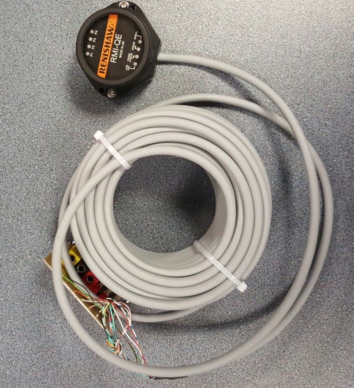
KQGRMI-QE
Mar 23, 2021RMI-QE Radio Machine Interface
Equipment Class
DSS - Part 15 Spread Spectrum Transmitter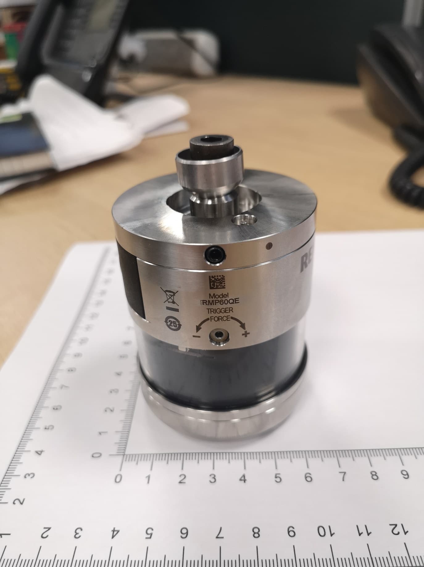
KQGRMP60QE
Apr 07, 2020Radio Machine Probe
Equipment Class
DSS - Part 15 Spread Spectrum Transmitter
KQGRTSQE
Apr 07, 2020Radio Tool Setter
Equipment Class
DSS - Part 15 Spread Spectrum Transmitter