KQP07Energy Saving Lamps
Chuan Shih Industrial Co Ltd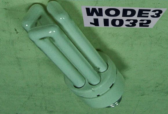
Click to zoom
Application Details
- Equipment Class
- 8CC - Part 18 Consumer Device
- Date of Grant
- Dec 05, 2001
- Application Purpose
- Original Equipment
- Date of Application
- Dec 05, 2001
- Equipment Note
- Energy Saving Lamps
- Frequency Range
- 0.04800000 - 0.06800000
- Company
- Chuan Shih Industrial Co Ltd
- Country
- Taiwan
Documents & Files
Document Text
Text extracted from the exhibit documents filed with the FCC. Open a document above to read the original.
Users Manual
Operation and Servicing instructions CAUTION: Use indoors and do not use in wet location or room (bathroom shower room etc.). This device is not intended for use with emergency exit fixtures or emergency exit lights. To prevent risk of fire or product damage, do not use this adapter on dimming circuits, electronic timers or photo cells. Added weight of fitting may cause instability of free-standing portable lamps. Use only with portable lamp in which the distance from the bottom of the base to the top of the lamp holder does not exceed three (3) times the base width. Use only with portable lamps which are provided with lamp shades. Use only on 120V 60 hertz circuits. May not start at temperatures below 32 (0). Fluorescent lamp lumens decline during their longer life. There are no serviceable parts inside this product. Do not open the sealed portion of the bulb or adapter. To do so could create a safety hazard. This product may cause interference to radio equipment and should not be installed near maritime safety communications equipment or other critical navigation or communication equipment operating between 0.45-30 MHz. *BASED ON BURNING 4 HOURS DAILY 9000 HOURS RATED LIFE
External Photos
PHOTOS OF TESTING A. EUT front side view (Mode 1) B. EUT back side view PHOTOS OF TESTING C. EUT front side view (Mode 2) D. EUT back side view PHOTOS OF TESTING E. EUT front side view (Mode 3) F. EUT back side view
ID Label/Location Info
FCC LABLE Sample of FCC ID Label Made in Taiwan FCCID:KQP07 FCC LABLE Sample of FCC ID Label Made in Taiwan FCCID:KQP07 Sample of FCC ID Label Made in Taiwan FCCID:KQP07
Internal Photos
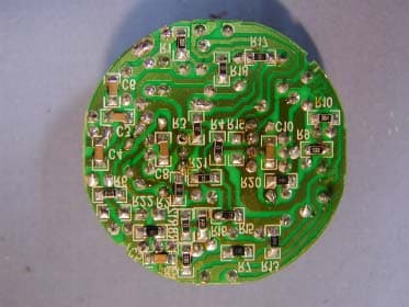
PHOTOS OF TESTING A. EUT inside whole view (Mode 1) PHOTOS OF TESTING B. Main board component side (Mode 1) C. Main board solder side PHOTOS OF TESTING D. EUT inside whole view (Mode 2) PHOTOS OF TESTING E. Main board component side (Mode 2) F. Main board solder side PHOTOS OF TESTING G. EUT inside whole view (Mode 3) PHOTOS OF TESTING H. Main board component side (Mode 3) I. Main board solder side
Test Report
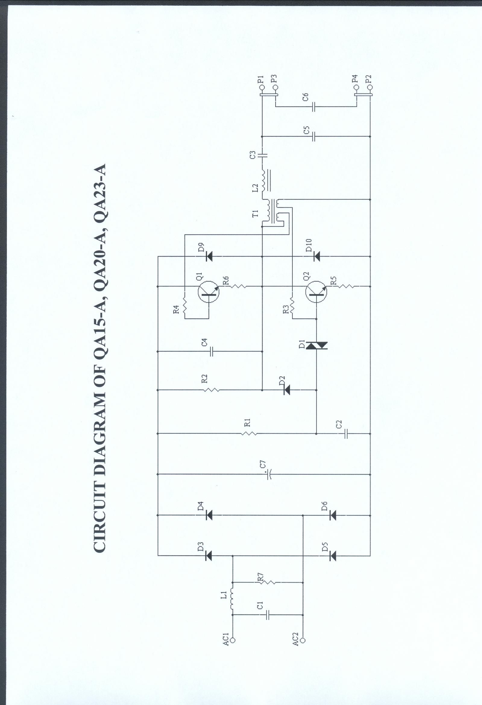
Class B Certification Application Under Part 18, Subpart B EUT ENERGY SAVING LAMPS MODEL QA15-A, QA20-A, QA23-A FCC ID KQP07 SRT REPORT # FID1I035 PREPARED FOR CHUAN SHIH INDUSTRIAL CORPORATION LTD. NO. 59, SHING-KONG 4TH RD., TA-SHING INDUSTRIAL DISTRICT, TIEN-CHUNG, CHANG-HUA, TAIWAN, R.O.C. Spectrum Research & Testing Lab. FCC ID KQP07 Report # FID1I035 PAGE 2 OF 22 Spectrum Research & Testing Lab. FCC ID KQP07 Report # FID1I035 PAGE 3 OF 22 EMI TESTING REPORT EUT : ENERGY SAVING LAMPS MODEL : QA15-A, QA20-A, QA23-A FCC ID : KQP07 PREPARED FOR CHUAN SHIH INDUSTRIAL CORPORATION LTD. NO. 59, SHING-KONG 4TH RD., TA-SHING INDUSTRIAL DISTRICT, TIEN-CHUNG, CHANG-HUA, TAIWAN, R.O.C PREPARED BY SPECTRUM RESEARCH & TESTING LABORATORY INC. NO. 101-10 , LING 8 , SHAN-TONG LI CHUNG – LI CITY , TAOYUAN, TAIWAN , R. O. C. TEL (03) 4987684 FAX (03) 4986528 Spectrum Research & Testing Lab. FCC ID KQP07 Report # FID1I035 PAGE 4 OF 22 TABLE OF CONTENTS 1. TEST REPORT CERTIFIICATION................................................................ 5 2. TEST STATEMENT 2 . 1 TEST STATEMENT.............................................................................. 6 2 . 2 DEPARTURE FROM DOCUMENT POLICIES, PROCEDURE OR SPECIFICATIONS, TEST STATEMENT....................... 6 3. EUT MODIFICATIONS................................................................................. 7-8 4. CONDUCTED POWER LINE TEST 4 . 1 TEST EQUIPMENT.............................................................................. 9 4 . 2 TEST PROCEDURE.............................................................................. 9 4 . 3 TEST SETUP....................................................................................... 10 4 . 4 CONFIGURATION OF THE EUT......................................................... 11 4 . 5 EUT OPERATING CONDITION............................................................. 12 4 . 6 EMISSION LIMITS............................................................................... 12 4 . 7 CONDUCTED EMISSION TEST RESULTS............................................. 13-15 5. RADIATED EMISSION TEST 5 . 1 TEST EQUIPMENT.............................................................................. 16 5 . 2 TEST PROCEDURE............................................................................. 17 5 . 3 TEST SETUP...................................................................................... 17-18 5 . 4 CONFIGURATION OF THE EUT......................................................... 19 5 . 5 EUT OPERATING CONDITION............................................................. 19 5 . 6 EMISSION LIMITS............................................................................... 19 5 . 7 RADIATED EMISSION TEST RESULTS................................................ 20-22 Spectrum Research & Testing Lab. FCC ID KQP07 Report # FID1I035 PAGE 5 OF 22 1. TEST REPORT CERTIFICATION APPLICANT CHUAN SHIH INDUSTRIAL CORPORATION LTD. ADDRESS NO. 59, SHING-KONG 4TH RD., TA-SHING INDUSTRIAL DISTRICT, TIEN-CHUNG, CHANG-HUA, TAIWAN, R.O.C. EUT DESCRIPTION ENERGY SAVING LAMPS (A) POWER SUPPLY 110V/60Hz (B) MODEL QA15-A, QA20-A, QA23-A (C) FCC ID KQP07 FINAL TEST DATE 10/09/2001 MEASUREMENT PROCEDURE USED * PART 15 SUBPART C OF FCC RULES AND REGULATIONS ( 47 CFR PART 15) * ANSI C63.4 - 1992, FCC/OET MP - 5 1986 * TEST PROCEDURE AND DATA ARE TRACEABLE TO NATIONAL OR INTERNATIONAL STANDARDS. We hereby certify that The measurements contained in this report were made in accordance with the procedures indicated, and the energy emitted by the equipment was found to be within the limits applicable. TESTING ENGINEER DATE 10/09/2001 Moore Weng SUPERVISOR DATE 10/09/2001 Sunyou Chen APPROVED BY DATE 10/09/2001 Johnson Ho Spectrum Research & Testing Lab. FCC ID KQP07 Report # FID1I035 PAGE 6 OF 22 2. TEST STATEMENT 2 . 1 TEST STATEMENT 1. This statement is to explain the test condition of this project. The EUT was the test condition of each test item. 2. The data was shown in this report reflects the worst – case data for the condition as the summary of test result. 3. EUT conditions. Mode Model Working frequency(KHz) Length(mm) Wattage(W) Mode 1 QA15-A 48 142 15 Mode 2 QA20-A 48 160 20 Mode 3 QA23-A 48 173 23 4. NVLAP logo is to be approved by management (it is according to NVLAP requirement if it need) before use. 2 . 2 DEPARTURE FROM DOCUMENT POLICIES, PROCEDURE OR SPECIFICATIONS , THE STATEMNT 1. Did have Any departure from document policies & procedures or from specifications. Yes , No . If yes , the description as below. 2. .The certificate and report shall not be reproduced except in full , without the written approval of SRT laboratory. 3. .The report must not be used by the client to claim product endorsement by NVLAP or any agency the government. 4. This product is a test sample that was shown as the photos of this test report only. 5. The effect that the results relate only to the items tested. Spectrum Research & Testing Lab. FCC ID KQP07 Report # FID1I035 PAGE 7 OF 22 3. EUT MODIFICATIONS No modification by SRT lab. Spectrum Research & Testing Lab. FCC ID KQP07 Report # FID1I035 PAGE 8 OF 22 Spectrum Research & Testing Lab. FCC ID KQP07 Report # FID1I035 PAGE 9 OF 22 4. CONDUCTED POWER LINE TEST 4 . 1 TEST EQUIPMENT The following test equipment were used during the conducted power line test EQUIPMENT/ FACILITIES SPECIFICATIONS MANUFACTURER MODEL#/ SERIAL# DATE OF CAL. & CAL. CENTER DUE DATE FINAL TEST EMI TEST RECEIVER 9 KHz TO 30 MHz ROHDE & SCHWARZ ESHS30/ 826003/008 MARCH 2001 R & S 1Y EMI TEST RECEIVER 9 KHz TO 2750 MHz ROHDE & SCHWARZ ESCS30/ 830245/012 JULY 2001 ETC 1Y √ LISN 5 uH, 50 ohm FCC FCC-LISN-5-50-1/ 2021 MARCH 2001 ETC 1Y √ SIGNAL GENERATOR 9 KHz TO 1080 MHz ROHDE & SCHWARZ SMY01/ 841104/019 MARCH 2001 ETC 1Y √ POWER CONVERTER 50 TO 300 VAC 47 TO 63/50/60Hz AFC AFC-2KBB/ F100030030 APRIL 2001 SRT 1Y √ 4 . 2 TEST PROCEDURE The EUT was tested according to ANSI C63.4 – 1992, FCC/OET MP - 5 198…
Text truncated - open the document above for the full version.
Test Setup Photos
PHOTOS OF TESTING A. Conducted test front view (Mode 1) B. Conducted test back view PHOTOS OF TESTING C. Conducted test front view (Mode 2) D. Conducted test back view PHOTOS OF TESTING E. Conducted test front view (Mode 3) F. Conducted test back view PHOTOS OF TESTING G. Open site test front view (Mode 1) H. Open site test back view PHOTOS OF TESTING I. Open site test front view (Mode 2) J. Open site test back view PHOTOS OF TESTING K. Open site test front view (Mode 3) L. Open site test back view
Contact Information
Applicant
Lu Lian Fu(Engineering Manager)
Test Firm
Spectrum Research & Testing Lab.Linda Chiang
Technical Specifications
| # | Rule Parts | Frequency Range | Power Output |
|---|---|---|---|
| 1 | 18 | 0.048 MHz - 0.068 MHz | - |
Other Applications from Chuan Shih Industrial Co Ltd
KQP09
Oct 05, 2003ENERGY SAVING LAMP
Equipment Class
8CC - Part 18 Consumer Device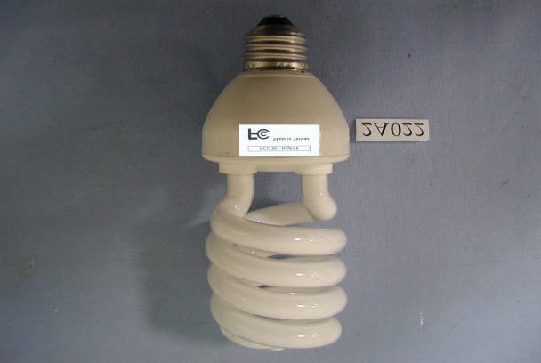
KQP08
Feb 05, 2002Energy Saving Lamps
Equipment Class
8CC - Part 18 Consumer Device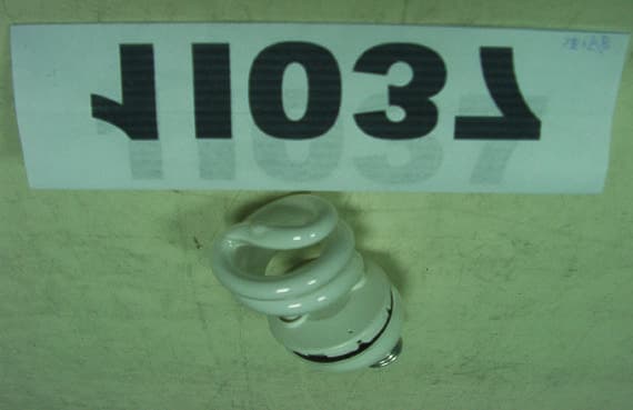
KQP05
Dec 05, 2001Energy Saving Lamps
Equipment Class
8CC - Part 18 Consumer Device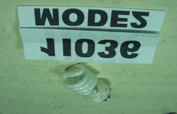
KQP06
Dec 05, 2001Energy Saving Lamp
Equipment Class
8CC - Part 18 Consumer Device
KQP04
Apr 20, 2000Energy saving lamps
Equipment Class
8CC - Part 18 Consumer Device