KSF-R1001PAR100-1-PA Aperio Reader
Securitron Magnalock Corp
Click to zoom
Application Details
- Equipment Class
- DTS - Digital Transmission System
- Date of Grant
- Mar 19, 2014
- Application Purpose
- Original Equipment
- Date of Application
- Mar 19, 2014
- Equipment Note
- R100-1-PA Aperio Reader
- Frequency Range
- 2405.00000000 - 2475.00000000
- Company
- Securitron Magnalock Corp
- Country
- United States
Documents & Files
Document Text
Text extracted from the exhibit documents filed with the FCC. Open a document above to read the original.
Users Manual
Part Number 500-24045, Rev. A ©2013, Securitron, Inc. 1 R100 Reader Installation Instructions Package Contents Recommended Tools Approved Credential: i.e., iCLASS or Prox ID card Level Pencil, wax pencil Optional Dress Cover: R100-DCA Optional Clamping device Product Specifications Wireless Frequency: 2.4 GHz, IEEE 802.15.4, using AES 128bit encryption Lock Battery Type: CR2, providing 35,000 Cycles FCC Part 15, Class B Compliant, Industry Canada, CE Compliant Reader Operating Temperature: -40F (-40C) to 122 F (+50C) Credentials Supported: 125kHz Proximity or 13.56MHz iCLASS credentials are supported depending on reader model. For technical support please call 1-800-810-9473 System Overview The R100 wireless reader installs in locations where wiring may be difficult or undesired for aesthetic reasons. The R100 wireless reader connects to an access control system through an Aperio communication hub. The communication hub connects to the access control system with wiegand or RS-485 wiring. When a credential card is presented to the reader the request for access is sent wirelessly to the communication hub. The communication hub then communicates to the access control system where the decision is made to grant or deny access. When access is granted the access control system unlocks the locking device seperately. Glue Reader Screws CR2 Battery Hex Wrench Securitron Magnalock Corp. Phoenix, AZ 800.624.5625 www.securitron.com Part Number 500-24045, Rev. A ©2013, Securitron, Inc. 2 1. Preparing the R100 Use a level to mark the position. Hold the reader body on the outside of the window and position it where you would like it to be mounted. 2. Insert Battery Install the battery, ensure correct orientation. The reader will self test and beep once. 3. Mounting the Unit The R100 can be mounted using glue or wood screws based on your needs. 3a. Apply Glue It is recommended that a thin thread of glue is applied to three sides of the back-plate as shown. This allows oxygen to enter and aid in the curing process. Do not use tissue or a brush to spread the adhesive. Quickly affix to the pre-marked area and hold or clamp until the adhesive has bonded (at least five seconds) The seal becomes functional within a short time and permanent after 24- 72 hours. Note the rate of cure depends on the ambient relative humidity. The best results are achieved when the relative humidity in the working environment is 40-60% at 22 ̊C. Lower humidity leads to a slower cure. High humidity accelerates it, but may impair the final strength of the bond. Glue line Position mark Battery Pull the cover up while pressing on the LED Use a pencil to mark this point on the window Part Number 500-24045, Rev. A ©2013, Securitron, Inc. 3 3b. Mounting with wood screws This is an alternate method for mounting the R100 to your door. Separate the components by gripping the electronic module at the noted side areas. Rock up, pull down, and lift out. Pre-drill through the mounting plate at the four corners and insert wood screws. Reattach electronic module by sliding the top under the mounting plate’s raised edges and pressing down firmly until it clicks. 4. Test Reader Reattach cover and insert screw with the included hex wrench. Use a credential known to the access control system to confirm it will read as desired. A green LED indicates access is granted. Refer to the LED reference card for any other codes. 5. Optional: Attach Dress Cover A separately purchased dress cover (R100-DCA) can be installed on the inside of a glass mounting surface. Peel the backing from the adhesive on the cover and affix to the window. Cover Screw Dress Cover R100 (rear view) Mounting Plate Side grip areas Wood screws Part Number 500-24045, Rev. A ©2013, Securitron, Inc. 4 WARNING FCC Statement This equipment has been tested and found to comply with the limits for a class B digital device, pursuant to part 15 of the FCC Rules. These limits are designed to provide reasonable protection against harmful interference in a residential installation. This equipment generates, uses, and can radiate radio frequency energy and if not installed and used in accordance with the instructions, may cause harmful interference to radio communications. However, there is no guarantee that interference will not occur in a particular installation. If this equipment does cause harmful interference to radio or television reception, which can be determined by turning the equipment off and on, the user is encouraged to try to correct the interference by one or more of the following measures: Reorient or relocate the receiving antenna. Increase the separation between the equipment and receiver. Connect the equipment into an outlet on a circuit different from that to which the receiver is connected. Consult the dealer or an experienced radio/TV technician for help. Operation with non-approved equipment is likely to result in interference to radio and TV reception. The user is cautioned that changes and modifications made to the equipment without the approval of manufacturer could void the user’s authority to operate this equipment. IC Statement This device complies with Industry Canada license-exempt RSS standards(s). Operation is subject to the following two conditions: (1) this device may not cause interference, and (2) this device must accept any interference, including interference that may cause undesired operation. Conformité aux normes FCC Cet équipement a été testé et trouvé conforme aux limites pour un dispositif numérique de classe B, conformément à la Partie 15 des règlements de la FCC. Ces limites sont conçues pour fournir une protection raisonnable contre les interférences nuisibles dans une installation résidentielle. Cet équipement génère, utilise et peut émettre des fréquences radio et, s'il n'est pas installé et utilisé conformément ment aux instructions du fabricant, peut causer des interferences nuisibles aux communications radio. Rien ne garantit cependant que …
Text truncated - open the document above for the full version.
Attestation Statements
Assa Abloy EMS&OEM 10027 S. 51st Street, Ste 102 Phoenix, AZ 85044 Tel +1 623-582-4626 February 11, 2014 To whom it may concern, ASSA ABLOY is the largest global supplier of intelligent locks and security solutions. Its products account for more than one in ten of all lock and security installations worldwide. Assa Abloy was formed in 1994 when ASSA AB was detached from Swedish security firm Securitas AB. Shortly thereafter, the Finnish high-security lock manufacturer Abloy Oy (a subsidiary of the Finnish company Wärtsilä) was acquired. The company was introduced to the Stockholm stock exchange later the same year. Assa Abloy has since made over 150 acquisitions. Securitron Magnalock Corporation is one of the leading manufacturers of magnetic locks and electromechanical exit devices in the US.Securitron was purchased and consolidated by Assa Abloy in 1998. In 1999, Hanchett Entry Systems was acquired by Assa Abloy throught the purchase of effeff, their owners at the time. Hanchett Entry Systems is committed to being the leading provider of innovative electromechanical locking solutions and support, creating safety, security and peace of mind for our customers, while providing an environment that enables employees to contribute and fulfill their potential. Sincerely, Andrew Wilding EM Product Development Engineer ASSA ABLOY AEHG 225 Episcopal Rd Berlin, CT 06037 P: 860.828.7291
External Photos
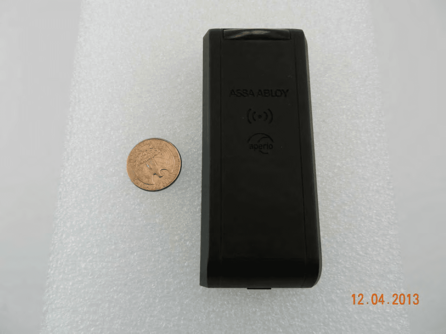
Securitron Magnalock Corp. 10027 S. 51st Street, Ste 102 Phoenix, AZ 85044 Tel +1 623-582-4626 R100-1-PA Photos Exterior Photos Placed next to a quarter for scale Side view Orthoganal view
ID Label/Location Info
2.00 1.00 4X R.09 0 8X .13 1.01 1.86 0 .06 .33 .42 .56 .635 .787 .86 A 6 7 .24 .21 DETAIL A SCALE 4 : 1 SIZE RELATIONSHIP SHALL BE MAINTAINED REVISIONS ZONEREV.CR#DESCRIPTIONREV BYAPPROVEDDATE X01410-13CR 410-1311/21/2013 4 3 2 1 4 3 2 1 F E D C B A F E D C B A NOTES: UNLESS OTHERWISE SPECIFIED. COMPONENTS AND OR PARTS TO COMPLY WITH1. EU DIRECTIVE 2002/95/EC (RoHS). MATERIAL: COATED PAPER WITH PERMANENT LATEX2. ADHESIVE. USE LABEL P/N: 3000021.006 OR HES APPROVED EQUIVALENT. WHITE LABEL WITH BLACK LETTERING.3. FINISH: PRINTED IN DENSE BLACK INK. TEXT SHALL4. BE SHARP AND LEGIBLE. FONT: ARIAL5. FONT HEIGHT: 4 POINT MINIMUM ALIGNMENT: LEFT JUSTIFIED SECURITRON LOGO DEFINED BY DRAWING 49-00052.6. APERIO LOGO DEFINED BY DRAWING 4000505.002.7. PARTS SHALL BE CLEAN AND FREE OF FOREIGN8. MATERIAL. PARTS SHALL BE PACKAGED TO PREVENT DAMAGE9. RESULTING FROM SHIPPING, STORAGE, AND HANDLING. TITLE UNRELEASED XDJ MFG ENGR LABEL: FCC, APERIO, R100, PROX DWG. NO. ssullivan LAST SAVED BY: 11/21/2013 PRINT DATE: SHEET 1 OF 1 SCALE: 2:1 X01B 5080021.011 RC JP SPS X X 09/25/13 3RD ANGLE PROJECTION HANCHETT ENTRY SYSTEMS, INC. 10027 S. 51st Street, Suite 102 - Phoenix AZ 85044 P (623)582-4626 - F (623)582-4641 THIS DOCUMENT IS THE CONFIDENTIAL PROPERTY OF HES, INC. AND IS LOANED SUBJECT TO RETURN UPON DEMAND. TITLE TO THIS DOCUMENT IS NEVER TO BE SOLD OR TRANSFERRED FOR ANY REASON. THIS DOCUMENT IS TO BE USED ONLY PURSUANT TO WRITTEN LICENSE OR WRITTEN INSTRUCTIONS OF HES, INC. ALL RIGHTS TO DESIGN AND INVENTIONS ARE RESERVED BY HES, INC. POSSESSION OF THE DOCUMENT IS ACCEPTED SUBJECT TO THE FOREGOING. © HES, INC. 2013 STATUS: R&D QA DRAWN BY DATENAME UNLESS OTHERWISE SPECIFIED DIMENSIONS ARE IN INCHES TOLERANCES ARE: FRACTIONAL 1/32 ANGLES 1 .XX .01 .XXX .005 DO NOT SCALE DRAWING INTERPRET PER ASME Y14.5M-2009 REV. SIZE FAMILY NAME:
Internal Photos
Interior Photos Antenna board Antenna board mounted on main board Side view All boards with PCB tub and light guide Assembled unit Top view Top view next to cover Side view (distance between antenna and cover = 1.5mm)
Test Report
FCC : Accredited IC recognized # 3462B-1 CETECOM Inc. 411 Dixon Landing Road Milpitas, CA 95035 U.S.A. Phone: + 1 (408) 586 6200 Fax: + 1 (408) 586 6299 E-mail: [email protected] http://www.cetecom.com CETECOM Inc. is a Delaware Corporation with Corporation number: 2905571 V3.0 2010-10-30 © Copyright by CETECOM FCC/IC Partial Scope Test Report FOR Manufacturer: Securitron Magnalock Corp. Model Number: R100-1-PA Product Description: Aperio Wall Mounted Reader FCC ID: KSF-R1001PA IC Certification Number: 11564A-R1001PA FCC CFR 47 Part 15.247 for DTS IC RSS-210 Issue 8, Annex 8 TEST REPORT #: EMC_HANC1-001-13501_R100LF_DTS-R DATE: March 11, 2014 Test Report #: EMC_HANC1-001-13501_R100LF_DTS-R FCC ID: KSF-R1001PA Date of Report : March 11, 2014 IC Cert. No.: 11564A-R1001PA TABLE OF CONTENTS 1 Assessment ......................................................................................................................................... 3 2 Administrative Data .......................................................................................................................... 4 2.1 Identification of the Testing Laboratory Issuing the Test Report ............................................................. 4 2.2 Identification of the Client ........................................................................................................................ 4 2.3 Identification of the Manufacturer ............................................................................................................ 4 3 Equipment under Test (EUT) .......................................................................................................... 5 3.1 Specification of the Equipment under Test ............................................................................................... 5 3.2 Identification of the Equipment Under Test (EUT) .................................................................................. 6 3.3 Identification of Accessory Equipment ..................................................................................................... 6 3.4 Other EUT Notes ...................................................................................................................................... 6 4 Summary of Measurement Results ................................................................................................. 7 5 Measurement Information ............................................................................................................... 8 5.1 Dates of Testing ....................................................................................................................................... 8 5.2 Measurement Uncertainty ......................................................................................................................... 8 5.3 Nominal EUT Conditions During Test ..................................................................................................... 8 5.4 Nominal Environmental Conditions During Test ..................................................................................... 8 5.5 Measurement Method ............................................................................................................................... 8 5.6 Radiated Measurement Procedure ............................................................................................................. 8 5.6.1 Sample Calculations for Radiated Measurements .............................................................................. 11 5.7 Associated Test Reports .......................................................................................................................... 11 5.8 Other Testing Notes ................................................................................................................................ 11 6 Measurement Results ...................................................................................................................... 12 6.1 Antenna Gain / EIRP ............................................................................................................................ 12 6.1.1 References ........................................................................................................................................... 12 6.1.2 Testing Notes ...................................................................................................................................... 12 6.1.3 Test Result ........................................................................................................................................... 12 6.1.4 Measurement Verdict .......................................................................................................................... 12 6.2 Unwanted Emissions at the Band Edges – Radiated ............................................................................... 13 6.2.1 References ........................................................................................................................................... 13 6.2.2 Spectrum Analyzer Settings ................................................................................................................ 13 6.2.3 Testing Notes ...................................................................................................................................... 13 6.2.4 Measurement Verdict .......................................................................................................................... 13 6.2.5 Test Plots ............................................................................................................................................ 14 6.3 Unwanted Emissions into Restricted Frequency Bands - Radiated ........................................................ 18 6.3.1 References .......................................................................................................................................…
Text truncated - open the document above for the full version.
Test Setup Photos
Project #: EMC_HANC1-001-13501_R100LF FCC ID: KSF-R1001PA IC Cert. No.: 11564A-R1001PA Page 1 of 4 Test Setup Photographs Model Number: R100-1-PA Product Description: Aperio Wall Mounted Reader Manufacturer: Securitron Magnalock Corp. FCC ID: KSF-R1001PA IC Certification Number: 11564A-R1001PA Test Site Information: CETECOM Inc. Milpitas, CA USA Project #: EMC_HANC1-001-13501_R100LF FCC ID: KSF-R1001PA IC Cert. No.: 11564A-R1001PA Page 2 of 4 RF Antenna Port Conducted Test Setup: Project #: EMC_HANC1-001-13501_R100LF FCC ID: KSF-R1001PA IC Cert. No.: 11564A-R1001PA Page 3 of 4 Radiated Emissions Test Setup: <30 MHz Measurement setup: 30MHz -1 GHz Measurement setup: Project #: EMC_HANC1-001-13501_R100LF FCC ID: KSF-R1001PA IC Cert. No.: 11564A-R1001PA Page 4 of 4 >1 GHz Measurement setup: >18 GHz Measurement setup:
Contact Information
Test Firm
CETECOM Inc.Meinolf Glunz
[email protected]408-586-6301
Technical Specifications
| # | Rule Parts | Frequency Range | Power Output |
|---|---|---|---|
| 1 | 15C | 2.40 GHz - 2.48 GHz | 20.00 µW |
Other Applications from Securitron Magnalock Corp
KSF-R1001SE
Mar 18, 2014R100-1-SE Aperio Reader
Equipment Class
DXX - Part 15 Low Power Communication Device Transmitter