KSME1008500Remote Control Transmitter for Bed
Raven Industries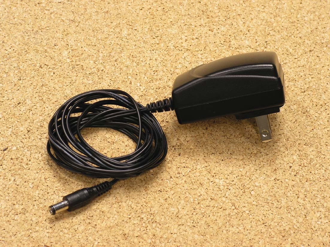
Click to zoom
Application Details
- Equipment Class
- DXX - Part 15 Low Power Communication Device Transmitter
- Date of Grant
- Apr 15, 2010
- Application Purpose
- Original Equipment
- Date of Application
- Apr 14, 2010
- Equipment Note
- Remote Control Transmitter for Bed
- Frequency Range
- 2405.00000000 - 2480.00000000
- Company
- Raven Industries
- Country
- United States
Documents & Files
Document Text
Text extracted from the exhibit documents filed with the FCC. Open a document above to read the original.
Users Manual
Wi-Fi Bridge Setup / Operation Guide www.adjustablesbyleggett.com 993011XX EDR11XXX 10/09 iPhone™ and iPod™ touch functionality only. Copyright © 2009 Leggett & Platt, Inc. Table of Contents Before Beginning ........................................................................ 4 Prodigy™ Wi-Fi Bridge Receiver Installation .............................. 5 Prodigy™ Bridge Application Setup ........................................... 7 Prodigy™ Position Screen .......................................................... 11 Prodigy™ Massage Screen ........................................................ 12 Prodigy™ Presets Screen ........................................................... 13 Prodigy™ Sleep Timer Screen ................................................... 14 Prodigy™ More Screen .............................................................. 15 Prodigy™ Gentle Wake Alarm Screen ....................................... 16 Prodigy™ Diagnostics Screen .................................................... 17 FCC DISCLAIMER Changes or modifications not expressively approved by the party responsible for compliance could void the user’s authority to operate the equipment. 4 Prodigy™ Wi-Fi Bridge Setup / Operation Guide 993011XX STEP 1 Before beginning Prodigy™ Wi-Fi Bridge setup, be sure you have uploaded the Prodigy Bridge App. to your iPhone™ or iPod™ touch (FIGuRE 1). Go to . . . FIGuRE 1: Home screen with Prodigy™ Bridge App. Before Beginning Prodigy™ Wi-Fi Bridge Setup / Operation Guide 993011XX 5 Prodigy™ Wi-Fi Bridge Receiver Installation STEP 2 Locate the Prodigy™ Wi-Fi Bridge receiver and electrical power cord (FIGuRE 2). FIGuRE 2: Prodigy™ Wi-Fi Bridge receiver and electrical power cord. ACTIvATE BuTTOn TRAnSMISSIOn LIGhT ELECTRICAL POWER CORD WI-FI BRIDGE RECEIvER 6 Prodigy™ Wi-Fi Bridge Setup / Operation Guide 993011XX Prodigy™ Wi-Fi Bridge Receiver Installation STEP 3 Insert the power cord into the Prodigy™ Wi-Fi Bridge receiver, then plug into electrical power source (electrical surge protection device recommended, not included) (FIGuRE 3). LEARn BuTTOn TRAnSMISSIOn LIGhT POWER DOWn BOx ACTIvATE BuTTOn TRAnSMISSIOn LIGhT ELECTRICAL POWER CORD WI-FI BRIDGE RECEIvER FIGuRE 3: Prodigy™ Wi-Fi Bridge receiver power cord installation and activation button location. FIGuRE 4: Power down box learn button location. STEP 4 Press the activate button on the Prodigy™ Wi-Fi Bridge receiver for (1) second, then press the learn button on the Prodigy™ adjustable base power down box for (1) second (FIGuRES 3 and 4). The transmission light on both receiver boxes will flash on-and-off in succession indicating communication. NOTE: The Prodigy™ Wi-Fi Bridge receiver must be in the same general location as the power down box. Prodigy™ Wi-Fi Bridge Setup / Operation Guide 993011XX 7 STEP 5 Access the Settings screen from the home screen (FIGuRE 5). Select Wi-Fi Prodigyxxxxxxxx (number is particular to your device). Prodigy™ Bridge Application Setup FIGuRE 5: Settings screen. 8 Prodigy™ Wi-Fi Bridge Setup / Operation Guide 993011XX STEP 6 The Wi-Fi networks screen appears. Make sure Wi-Fi function is set to On. Select √ProdigyXXXXXXXX (FIGuRE 6). Prodigy™ Bridge Application Setup FIGuRE 6: Wi-Fi Networks screen. Prodigy™ Wi-Fi Bridge Setup / Operation Guide 993011XX 9 STEP 7 Select the Prodigy™ Bridge App. from the home screen (FIGuRE 1). FIGuRE 1: Home screen with Prodigy™ Bridge App. Prodigy™ Bridge Application Setup 10 Prodigy™ Wi-Fi Bridge Setup / Operation Guide 993011XX STEP 8 A screen will appear indicating device is updating (FIGuRE 7). Let device complete updating (this may take a few moments). Prodigy™ Bridge Application Setup FIGuRE 7: Updating screen. Prodigy™ Wi-Fi Bridge Setup / Operation Guide 993011XX 11 Prodigy™ Position Screen STEP 9 The Position screen will appear indicating Prodigy™ Wi-Fi Bridge setup was successful (FIGuRE 8). Touch desired position button to activate adjustable base with your iPhone™ or iPod™ touch. FIGuRE 8: Position screen. (Active screen is highlighted.) 12 Prodigy™ Wi-Fi Bridge Setup / Operation Guide 993011XX Prodigy™ Massage Screen STEP 10 Touch the Massage icon to access massage function. The Massage screen will appear. Adjust the massage by touching the appropriate button (FIGuRE 9). FIGuRE 9: Massage screen. Prodigy™ Wi-Fi Bridge Setup / Operation Guide 993011XX 13 Prodigy™ Presets Screen STEP 11 Touch the Presets icon to access preset function. The Presets screen will appear. Touch a Presets button to return the bed to a factory preset position (FIGuRE 10). FIGuRE 10: Presets screen. To reprogram a preset position: 1. Adjust the bed to the desired position. 2. On the Presets screen, touch the edit button. 3. Select the preset number to save as the new position. 4. The new position is now programmed. 14 Prodigy™ Wi-Fi Bridge Setup / Operation Guide 993011XX Prodigy™ Sleep Timer Screen STEP 12 Touch the Sleep Timer icon to access sleep timer function. The Sleep Timer screen will appear. Set the sleep timer by touching the appropriate button (FIGuRE 11). FIGuRE 11: Sleep Timer screen. Prodigy™ Wi-Fi Bridge Setup / Operation Guide 993011XX 15 Prodigy™ More Screen STEP 13 Touch the More icon to access extra functions. The More screen will appear. Touch the appropriate button to access the Gentle Wake Alarm and Diagnostics screens (FIGuRE 12). FIGuRE 12: More screen. 16 Prodigy™ Wi-Fi Bridge Setup / Operation Guide 993011XX Prodigy™ Gentle Wake Alarm Screen STEP 14 After selecting the Alarm button from the More screen, the Gentle Wake Alarm screen will appear. Make sure Gentle Wake Alarm is set to On. Scroll to find the appropriate time and then touch the Set button (FIGuRE 13). FIGuRE 13: Gentle Wake Alarm screen. Prodigy™ Wi-Fi Bridge Setup / Operation Guide 993011XX 17 Prodigy™ Diagnostics Screen STEP 15 After selecting the Diagnostics button from the More screen, the Diagnostics screen will appear. A number will appear in the Fault Code field if ther…
Text truncated - open the document above for the full version.
Cover Letter(s)
March 28, 2010 Federal Communications Commission Equipment Approval Services P.O. Box 358315 Pittsburgh, PA 15251-5315 Re: Certification for Raven Transceiver Model/PN(s): KSME1008500 FCC ID: KSME1008500 IC: 2004A-E1008500 Please find enclosed application materials for certification of Raven Transceiver. We tested it and found it to comply with FCC Part 15. If there are any questions regarding the application or testing performed, please contact me at the above address or call 734-483-4211, fax 734-647-2106, or e-mail [email protected]. Sincerely, Valdis V. Liepa Research Scientist
Cover Letter(s)
Re: Certification for Raven Transceiver FCC ID: KSME1008500 IC: 2004A-E1008500 REQUEST FOR CONFIDENTIALITY Pursuant to FCC 47 CRF 0.457(d) and 0.459 and IC RSP-100, Section 10, Raven requests that a part of the subject application be held confidential. Raven has spent substantial effort in developing this product and it is one of the first of its kind in industry. Having the subject information easily available to "competition" would negate the advantage they have achieved by developing this product. Not protecting the details of the design will result in financial hardship. Type of Confidentiality Requested Exhibit Short Term Permanent (1) ID Label & Location Short Term Permanent (3) External Photos Short Term Permanent 1 (4) Block Diagram Short Term Permanent (5) Schematics Short Term Permanent (7) Test Setup Photos Short Term Permanent (8) User’s Manual Short Term Permanent (9) Internal Photos Short Term Permanent (10) Parts List & Placement Short Term Permanent (11) RF Exposure Short Term Permanent (12) Description of Operation 1. Block Diagram includes internal oscillator frequency information that the manufacturer considers to be proprietary. Permanent Confidentiality: Raven requests the exhibits listed above as permanently confidential be permanently withheld from public review. Short-Term Confidentiality (FCC Only): Raven requests the exhibits selected above as short term confidential be withheld from public view for a period of 45 days from the date of the Grant of Equipment Authorization and prior to marketing. If there are any questions regarding this request, please contact me at the above address or call 734-483-4211, fax 734-647-2106 or e-mail [email protected]. Sincerely, Valdis V. Liepa, Research Scientist University of Michigan
Cover Letter(s)
April 15, 2010 RE: ATCB008868 – Original Equipment & Single Certification Applications (model KSME1008500) FCC ID: KSME1008500 & IC: 2004A-E1008500 for Raven Industries The following is in response to the comments made on the above referenced application. 1. Please confirm that this frequency hopping transmitter had the hopping function stopped for the radiated emission test results shown in Tables 6.1(a) and 6.1(b) of the submitted test report. I could not find this information in the submitted test report. Yes, hopping was not employed for the test results depicted in Tables 6.1(a) and 6.1(b). 2. The submitted user manual is missing a statement warning the installer and/or the user of this device that a 20 cm separation distance must be maintained between this transmitter and any nearby person during operation. Please provide an amended user manual with this information. The user’s manual exhibit as been updated. 3. Please provide an Annex C of RSS-102 Issue 4 dated March 2010. The Annex B provided is from the old version of RSS-102 and IC has made statements that the new Annex C must be provided starting on March 29, 2010. Please note that ATCB has amended all our IC filing forms and documents accordingly. I intend to use the submitted RF exposure exhibit as the RF exposure technical brief required by Section 2.5 of the new RSS-102. This section states that the RF exposure technical brief may be limited to how the transmitter output power was derived. This annex has now been provided. 4. For Your Information – I will be changing the emission designator for this device to 2M43FXD since IC has decided that all frequency hopping spread spectrum transmitters may be described using the FXD designator. There is no need to provide an amended IC application form unless IC requests an amended one when I list this device on the REL in Canada.
RF Exposure Info
RF Exposure Statement Requirement: According to CFR 15 §1.1307 (b)(1), systems operating under the provisions of this section shall be operated in a manner that ensure that the public is not exposed to radio frequency energy level in excess of the Commission’s guideline. SAR Testing: This is a controlled device mounted underneath of a motorized bed, greater than 20 cm from the occupant. Worst case peak radiated power of the 802.15.4 radio is 95.2 dBuV/m @ 3m, or equivalently an EIRP of 1 mW. Worst case peak EIRP of the onboard WLAN module is 16.87 dBm, or 48.64 mW. Worst case coherent power addition would result in a EIRP of 49.64 mW. Health Hazard: The following table summarizes the power density at a distance of 20 cm from the device as calculated from FCC OET Bulletin 65. Table 6.3 Potential Health Hazard Radiation Level – Coherent Power Addtion WLAN EIRP (mW) S (mW/cm 2 ) PCB 49.64 0.00988 The following equations were used in calculating the power density (S). 10 )( 10)()( dBGain mWPomWEIRP and 2 2 )(4 )( )/( cmR mWEIRP cmmWS , R = 20 cm
Test Report
University of Michigan Radiation Laboratory FCC Part 15, IC RSS-210/Gen - Test Report No. 417124-563 Page 1 of 13 The University of Michigan Radiation Laboratory 3228 EECS Building Ann Arbor, MI 48109-2122 Tel: (734) 764-0500 Fax: (734) 647-2106 Measured Radio Frequency Emissions From Raven Industries Transceiver FCC ID: KSME1008500 IC: 2004A-E1008500 Test Report No. 417124-563 March 28, 2010 Copyright © 2010 For: Raven Industries 4372 Green Ash Drive Earth City, MO 63045 Contact: Nicholas Tsigolaroff [email protected] Phone: 314-291-2712 Fax: 314-291-0773 Testing supervised by: Measurements made by: Valdis V. Liepa Report Approved by:__________________________ Valdis V. Liepa Test report written by: Joseph D. Brunett Research Scientist Summary Tests for compliance with FCC Regulations, CFR 47, Part 15 and with Industry Canada RSS-210/Gen, were performed on a Raven, Model/FCC ID: KSME1008500, IC: 2004A-E1008500. This device under test (DUT) is subject to the rules and regulations as a Transceiver. In testing completed on March 25, 2010, the DUT tested met the allowed specifications for radiated emissions by more than 7.9 dB. AC Mains conducted emissions meet the allowed specifications by more than 5.0 dB. University of Michigan Radiation Laboratory FCC Part 15, IC RSS-210/Gen - Test Report No. 417124-563 Page 2 of 13 Table of Contents 1. Introduction ...................................................................................................................................... 3 2. Equipment Used ............................................................................................................................... 3 3. Device Under Test ........................................................................................................................... 4 3.1 Description & Block Diagram .............................................................................................. 4 3.2 Variants ................................................................................................................................. 4 3.3 Modes of Operation .............................................................................................................. 4 3.4 Exemptions ........................................................................................................................... 4 3.5 EMC Relevant Modifications ............................................................................................... 4 4. Emissions Limits .............................................................................................................................. 5 4.1 Radiated Emissions Limits .................................................................................................... 5 5. Measurement Procedures ................................................................................................................. 6 5.1 Semi-Anechoic Chamber Radiated Emissions ...................................................................... 6 5.2 Outdoor Radiated Emissions ................................................................................................. 6 5.3 Radiated Field Computations ................................................................................................ 6 5.4 Indoor Power Line Conducted Emissions ............................................................................. 6 5.5 Supply Voltage Variation ...................................................................................................... 7 6. Test Results ...................................................................................................................................... 7 6.1 Radiated Emissions ............................................................................................................... 7 6.1.1 Peak to Quasi-peak and Average Ratio ............................................................................. 7 6.1.2 Emission Spectrum ........................................................................................................... 7 6.1.3 Emission Bandwidth ......................................................................................................... 7 6.1.4 Supply Voltage and Supply Voltage Variation ................................................................. 7 6.2 Conducted Emissions ............................................................................................................ 7 University of Michigan Radiation Laboratory FCC Part 15, IC RSS-210/Gen - Test Report No. 417124-563 Page 3 of 13 1. Introduction This Raven Transceiver was tested for compliance with FCC Regulations, Part 15, adopted under Docket 87-389, April 18, 1989 as subsequently amended, and with Industry Canada RSS-210/Gen, Issue 7, June 2007. Tests were performed at the University of Michigan Radiation Laboratory Willow Run Test Range following the procedures described in ANSI C63.4-2003 "Methods of Measurement of Radio-Noise Emissions from Low-Voltage Electrical and Electronic Equipment in the Range of 9 kHz to 40 GHz". The Site description and attenuation characteristics of the Open Site facility are on file with FCC Laboratory, Columbia, Maryland (FCC Reg. No: 91050) and with Industry Canada, Ottawa, ON (File Ref. No: IC 2057A-1). 2. Equipment Used The pertinent test equipment commonly used in our facility for measurements is listed in Table 2.1 below. The middle column identifies the specific equipment used in these tests. The quality system employed at the University of Michigan Radiation Laboratory Willow Run Test Range has been established to ensure all equipment has a clearly identifiable classification, calibration expiry date, and that all calibrations are traceable to national standards. Table 2.1 Test Equipment. Test Instrument Used Manufacturer/Model Q Number Spectrum Analyzer (9kHz-26GHz) X Hewlett-Packard 8593E, SN: 3412A01131 HP8593E1 Spectrum Analyzer (9kHz-6.5GHz) X Hewlett-Packard 8595E,…
Text truncated - open the document above for the full version.
Contact Information
Applicant
Nicholas Tsigolaroff
Technical Contact
University of Michigan/EECSValdis V. Liepa
[email protected]734-483-4211
1301 Beal Avenue · Ann Arbor · United States
Test Firm
University of MichiganValdis Liepa
Technical Specifications
| # | Rule Parts | Frequency Range | Power Output |
|---|---|---|---|
| 1 | 15C | 2.40 GHz - 2.48 GHz | - |
Other Applications from Raven Industries
KSME1003925
Jul 09, 2006Remote Control Transmitter
Equipment Class
DSC - Part 15 Security/Remote Control Transmitter
KSMBR20543-45T
Mar 29, 2001Adjustable Bed Remote Control
Equipment Class
DSC - Part 15 Security/Remote Control TransmitterKSMBR20808T
Apr 15, 1997Bed Control Transmitter
Equipment Class
DSC - Part 15 Security/Remote Control TransmitterKSMBR20543T
Sep 08, 1996Adjustable Bed Control Transmitter
Equipment Class
DSC - Part 15 Security/Remote Control TransmitterKSMBR20077R1
Jul 25, 1993Remote Control Receiver for Adjustable Bed
Equipment Class
CRR - Superregenerative Receiver