KSN-UA662LDigital Blood Pressure Monitor
A&D Co Ltd
Click to zoom
Application Details
- Equipment Class
- DTS - Digital Transmission System
- Date of Grant
- Sep 24, 2023
- Application Purpose
- Original Equipment
- Date of Application
- Sep 21, 2023
- Equipment Note
- Digital Blood Pressure Monitor
- Frequency Range
- 2402.00000000 - 2480.00000000
- Company
- A&D Co Ltd
- Country
- Japan
Documents & Files
Document Text
Text extracted from the exhibit documents filed with the FCC. Open a document above to read the original.
Users Manual
Upper Arm Blood Pressure Monitor 6000 Series – Wireless Instruction Manual Original 1WMPD4004430A ❏ 1. Introduction The Equate upper arm blood pressure monitor is designed for ease of use and accuracy. This device will facilitate your daily blood pressure regimen. ❏We recommend that you read through this manual carefully before using the device for the first time. ❏This device is designed for use on adults, and is not intended for infants and children. ❏This device is designed for use to operate by yourself in the home healthcare environment to measure blood pressure and pulse rate of people for diagnosis. 2. Precautions FCC Compliance Information This device complies with Part 15 of FCC rules. Operation is subject to the following two conditions: 1. This device may not cause harmful interference, and 2. This device must accept any interference received, including interference that may cause undesired operations. ❏Precision components are used in the construction of this device. Extremes in temperature, humidity, direct sunlight, shock or dust should be avoided. ❏Clean the device and cuff with a dry, soft cloth or a cloth dampened with water and a neutral detergent. Never use alcohol, benzene, thinner or other harsh chemicals to clean the device or cuff. ❏Avoid tightly folding the cuff or storing the hose tightly twisted for long periods, as such treatment may shorten the life of the components. ❏Take care to avoid accidental strangulation of babies or infants with the hose. ❏Do not twist the air hose during measurement. This may cause injury due to continuous cuff pressure. ❏The device and cuff are not water resistant. Prevent rain, sweat and water from soiling the device and cuff. ❏Measurements may be distorted if the device is used close to televisions, microwave ovens, cellular telephones, X-ray or other devices with strong electrical fields. ❏Wireless communication devices, such as home networking devices, mobile phones, cordless phones and their base stations, and walkie-talkies can affect this blood pressure monitor. Therefore, a minimum distance of 12” / 30cm should be kept from such devices. ❏When reusing the device, confirm that the device is clean. ❏Used equipment, parts and batteries are not treated as ordinary household waste, and must be disposed of according to the applicable local regulations. ❏Do not modify the device. It may cause accidents or damage to the device. ❏To measure blood pressure, the arm must be squeezed by the cuff hard enough to temporarily stop blood flow through the artery. This may cause pain, numbness or a temporary red mark to the arm. This condition will appear especially when measurement is repeated successively. Any pain, numbness, or red marks will disappear with time. ❏Measuring blood pressure too frequently may cause harm due to blood flow interference. ❏Check that the operation of the device does not result in prolonged impairment of blood circulation, when using the device repeatedly. ❏Clinical testing has not been conducted on newborn infants and pregnant woman. Do not use on newborn infants or pregnant woman. ❏If you have had a mastectomy, please consult a doctor before using the device. ❏Do not let children use the device by themselves and do not leave the device within the reach of children, it may cause accidents or injury. ❏There are small parts that may cause a choking hazard if swallowed by mistake by infants. ❏Do not touch the batteries and the patient at the same time. That may result in electrical shock. ❏Use of accessories not detailed in this manual may compromise safety. ❏Should the battery short-circuit, it may become hot and potentially cause burns. ❏Allow the device to adapt to the surrounding environment before use (about one hour). ❏Do not inflate without wrapping the cuff around the upper arm. ❏Do not apply the cuff on an arm in which another medical device is attached. The equipment may not function properly. ❏People who have a severe circulatory deficit in the arm must consult a doctor before using the device, to avoid medical problems. ❏Do not self-diagnose the measurement results and start treatment by yourself. Always consult your doctor for evaluation of the results and treatment. ❏Do not apply the cuff on an arm with an unhealed wound. ❏Do not apply the cuff on an arm receiving an intravenous drip or blood transfusion. It may cause injury. ❏Do not use the device where flammable gases such as anesthetic gases are present. It may cause an explosion. ❏Do not use the device in highly concentrated oxygen environments, such as a high-pressure oxygen chamber or an oxygen tent. It may cause a fire or explosion. 3. Parts Identification Proper fit range Index Artery position symbol Air Hose Display START/STOP Button Clock Button Button Air Socket Air Connector Plug Battery Compartment Battery Cover Arm Cuff User Selection Button Display I.H.B. Symbol Movement Error Symbol Pressure Bar Indicator Heart Symbol AHA Classification Indicator MEMORY Symbol Average Symbol Systolic Pressure Diastolic Pressure Pulse Rate Date and Clock AM/PM Symbol Battery Indicator Users Bluetooth ® Connection Symbol 4. Symbols Symbols that appear on the display SymbolsFunction/MeaningRecommended Action Appears while measurement is in progress. It blinks when the pulse is detected. Measurement is in progress. Remain as still as possible. I.H.B. symbol appears when an irregular heartbeat is detected. It may appear when a very slight vibration like shivering or shaking is detected. –––––––––––– Appears when a body or arm movement is detected. –––––––––––– Previous measurements stored in memory. –––––––––––– Average data –––––––––––– FULL BATTERY The battery power indicator during measurement. –––––––––––– LOW BATTERY The battery power is low when it blinks. Replace all batteries with new ones when the symbol blinks. User1 and User2–––––––––––– AMTime in the morning–––––––––––– PMTime in the afternoon–––––––––––– The device is connecting to the Bluet…
Text truncated - open the document above for the full version.
Attestation Statements
4622 Runway Boulevard main 408 263 5333 www.andonline.com Ann Arbor MI 48108 fax 408 263 0119 Date: 9/1/2023 Federal Communications Commissions Authorization and Evaluation Division 7435 Oakland Mills Road Columbia, MD 21046 RE: CFR 47 §2.911 (d)(7) FCC US Agent Letter of Attestation FCC ID: KSN-UA662L Grantee FRN: 0018795823 To whom it may concern: FCC US Agent Agent Company Name: A&D Engineering, Inc. FCC FRN: 0026637405 Agent Contact Name: Jerry Wang Agent US Address: 4622 Runway Boulevard, Ann Arbor, MI 48108, United States Agent Email Address: [email protected] This letter is to confirm that we have accepted the responsibility to act as the U.S. Agent on behalf of A&D Company, Limited (“the applicant”) for the above referenced FCC ID. We are aware of the requirements and responsibilities of the applicant’s agent for service of process as outlined in the FCC section 2.911(d)(7) and Report and Order FCC 22-84 paragraph 63. Sincerely, Authorized Agent Contact Person Name: Jerry Wang Agent contact Job Title: Director of Engineering & QA Agent Company name: A&D Engineering, Inc.
External Photos
Front View Rear View External Photos Right Side View Left Side View Top View Bottom View
ID Label/Location Info
UA-662BLE Label
Internal Photos
Open Case Board surface back of Board BLE IC & Antenna
RF Exposure Info
JQA File No. :KL80230325 Issue Date : August 30, 2023 Page 50of 53 ControlNo. 23121-2102 7.7RF Exposure Considerations (KDB 447498 D01) The 1 g SAR test exclusion thresholds for 100 MHz to 6 GHz at test separation distances≤50 mm are determined by; [(max. power of channel, including tune-up tolerance, mW) / (min. test separation distance, mm)] ∙[√f (GHz) ] ≤3.0for 1 g SAR and ≤7.5 for 10 g extremity SAR, where -f (GHz) is the RF channel transmit frequency in GHz. -Power and distance are rounded to the nearest mW and mm before calculation. -The result is rounded to one decimal place for comparison. -When the minimumtest separation distanceis < 5 mm, a distance of 5 mm is applied. Band Freq. (MHz) Max. Power Distance (mm) Threshold Test Exclusion (dBm)(mW) BluetoothLE2480-5.00.3< 50.1YES Theminimumuserseparationdistancewasassumedtobe0mmforthepurposeoftheSARexclusion calculations. Conclusion: The device for BLEqualifies for the Standalone SAR test exclusion because the computed value is < 3.
Test Report
Page 1of 53 ControlNo. 23121-2102 JQA File No. :KL80230325 Issue Date:August 30, 2023 T E S T R EP O R T Applicant:A&D Company, Limited Address:1-243, Asahi, Kitamoto-shi, Saitama 364-8585, Japan Products:Digital Blood Pressure Monitor Model No.:UA-6000BLEWM Serial No.:-- TestStandard:CFR 47 FCC Rules and Regulations Part 15Subpart C FCC ID:KSN-UA662L TestResults:Passed Date of Receipt:August 1, 2023 DateofTest:August 10 ~ 25, 2023 Kosei Shibata Deputy Director Japan Quality Assurance Organization KitakansaiTesting Center SaitoEMC Branch 7-3-10, Saito-asagi, Ibaraki-shi, Osaka 567-0085, Japan ●The test results in this test report was made by using the measuring instruments which are traceable to national standards of measurement in accordance with ISO/IEC 17025. ●The applicable standard, testing condition and testing method which were used for the tests are based on the request of the applicant. ●The test results presented in this report relate only to the offered test sample. ●The contents for the equipment under test (EUT) such as identification information in clause 2and 6of this report were provided by the applicant. JQA is not responsible for the test results affected by the incorrect information. ●The contents of this test report cannot be used for the purposes, such as advertisement for consumers. ●This test report shall not be reproduced except in full without the written approval of JQA. ●VLAC does not approve, certify or warrant the product by this test report. VLAC-001-2 JQA File No. :KL80230325 Issue Date : August 30, 2023 Page 2of 53 ControlNo. 23121-2102 REVISION HISTORY File No.ContentsIssue Date KL80230325Initial IssueAugust 30, 2023 JQA File No. :KL80230325 Issue Date : August 30, 2023 Page 3of 53 ControlNo. 23121-2102 TABLE OF CONTENTS Page 1Summary of Test Results....................................................................................................................4 2Description of Equipment Under Test (EUT).....................................................................................5 2.1General Information........................................................................................................................5 2.2Channel List....................................................................................................................................5 3Test Location........................................................................................................................................6 4Accreditation of Test Laboratory.......................................................................................................6 5Measurement Uncertainty...................................................................................................................6 6Setup of EUT........................................................................................................................................7 6.1Test Configuration..........................................................................................................................7 6.2Test Arrangement (Drawings).......................................................................................................7 6.3Operating Condition.......................................................................................................................8 6.4Duty Cycle.......................................................................................................................................9 7Test Item.............................................................................................................................................10 7.199% Occupied Bandwidth............................................................................................................10 7.26 dB Emission Bandwidth............................................................................................................13 7.3Power Spectral Density................................................................................................................16 7.4Maximum Conducted Output Power...........................................................................................19 7.5Conducted Spurious Emission...................................................................................................21 7.6Radiated Spurious Emission.......................................................................................................29 7.7RF Exposure Considerations (KDB 447498 D01)......................................................................50 8Test Setup (Photographs).................................................................................................................51 JQA File No. :KL80230325 Issue Date : August 30, 2023 Page 4of 53 ControlNo. 23121-2102 1Summary of Test Results AppliedStandard:CFR 47 FCC Rules and Regulations Part 15–Radio Frequency Devices Subpart C–Intentional Radiators ItemFCC rulesResultNote Antenna Requirement§15.203Passed1 99%OccupiedBandwidth----2 6 dB Emission Bandwidth§15.247(a)(2)Passed Power Spectral Density§15.247(e)Passed Maximum ConductedOutput Power§15.247(b)(3)Passed Conducted Spurious Emission§15.247(d)Passed Radiated Spurious Emission §15.205, §15.209 and §15.247(d) Passed AC Powerline Conducted Emission§15.207Not Applicable3 RF Exposure §1.1310,§2.1091and §15.247(i) Passed 1)The EUT is designed to ensure that no antenna other than that furnished by the manufacturer shall be used. Information for antenna type is described in clause 2. 2)Reporting purposes only 3)The EUT is not connected to the AC mains. In the approval of test results, -No deviations were employed from the applied standard. -No modifications were conducted by JQA to achieve compliance to the limitations. Reviewed by Yasuhisa Sakai / Project Manager Testedby Yuji Shintaku / Assistant Manager JQA File No. :KL80230325 Issue Date : August 30, 2023 Page 5of 53 ControlNo. 23121-2102 2DescriptionofEquipment Under Test (…
Text truncated - open the document above for the full version.
Test Report
Ver.1.00 Sep 2023 1 Pattern Antenna PC8099 Datasheet 1. Description This antenna is a pattern antenna designed for Bluetooth communication of A&D blood pressure monitor “UA-662BLE”. 2. Specification Model: PC8099(Pattern Antenna) Vender: A&D Company, Limited Operating frequency range:2402-2480MHz Antenna gain (Design Value):-2.2dBi Ver.1.00 Sep 2023 2 3.Dimension actual board antenna Antenna Port Ver.1.00 Sep 2023 3 4. Characteristic (1)VSWR (2)Directivity Antenna axis definition _ see setup photos Ver.1.00 Sep 2023 4 ZY-Plane XZ-Plane XY-Plane Ver.1.00 Sep 2023 5 A&D Company, Limited 1-243, Asahi, Kitamoto-shi, Saitama-ken, 364-8585 Japan TEL: 81-48-593-1627 FAX: 81-48-593-1684 WEB: www.aandd.jp (3)Antenna Efficiency & Maximum Gain 2400MHz 2450MHz 2500MHz -7.3dB Antenna Efficiency -6.9dB -5.6dB Maximum Gain XZ-Plane -2.2dBi -2.5dBi XY-Plane ZY-Plane -2.8dBi
Test Setup Photos
JQA File No. :KL80230325 Issue Date : August 30, 2023 Page 51of 53 ControlNo. 23121-2102 8Test Setup (Photographs) 8.1Radiated Spurious Emission 9 kHz –30 MHz 8.2Radiated Spurious Emission 30 MHz –1000 MHz JQA File No. :KL80230325 Issue Date : August 30, 2023 Page 52of 53 ControlNo. 23121-2102 8.3Radiated Spurious Emission above 1 GHz –X axis – JQA File No. :KL80230325 Issue Date : August 30, 2023 Page 53of 53 ControlNo. 23121-2102 –Y axis – –Z axis – ---END OF REPORT ---
Test Setup Photos
Ver.1.00 Sep 2023 3 4. Characteristic (1)VSWR (2)Directivity Antenna axis definition X Y Z
Contact Information
Applicant
Seiji Haijima
Technical Contact
Japan Quality Assurance OrganizationMika Itagaki
[email protected]+81726405270
1-7-7, Ishimaru, · Minoh-shi, Osaka · Japan
Test Firm
Japan Qlty. Assur. Org. Kitakansai Testing CenterHiroyuki Nakamura
Technical Specifications
| # | Rule Parts | Frequency Range | Power Output |
|---|---|---|---|
| 1 | 15C | 2.40 GHz - 2.48 GHz | 300.00 µW |
Other Applications from A&D Co Ltd
KSN-52805ND05
Mar 25, 2026Digital Blood Pressure Monitor
Equipment Class
DTS - Digital Transmission SystemKSN-52805ND06
Mar 25, 2026Digital Blood Pressure Monitor
Equipment Class
DTS - Digital Transmission SystemKSN-52805ND02
Aug 18, 2024Digital Blood Pressure Monitor
Equipment Class
DTS - Digital Transmission System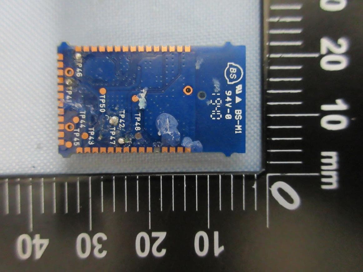
KSNPZ7128
Jan 21, 2021Bluetooth Low Energy (v4.2) module
Equipment Class
DTS - Digital Transmission System
KSNAD1321-10MW
Aug 08, 2013Wireless Module
Equipment Class
DTS - Digital Transmission System