KTF406-ELTSurvival Rescue Beacon, Raft Mounted
Astronics Luminescent Systems Inc
Click to zoom
Application Details
- Equipment Class
- TNB - Licensed Non-Broadcast Station Transmitter
- Date of Grant
- Jul 14, 2003
- Application Purpose
- Original Equipment
- Date of Application
- Apr 20, 2003
- Equipment Note
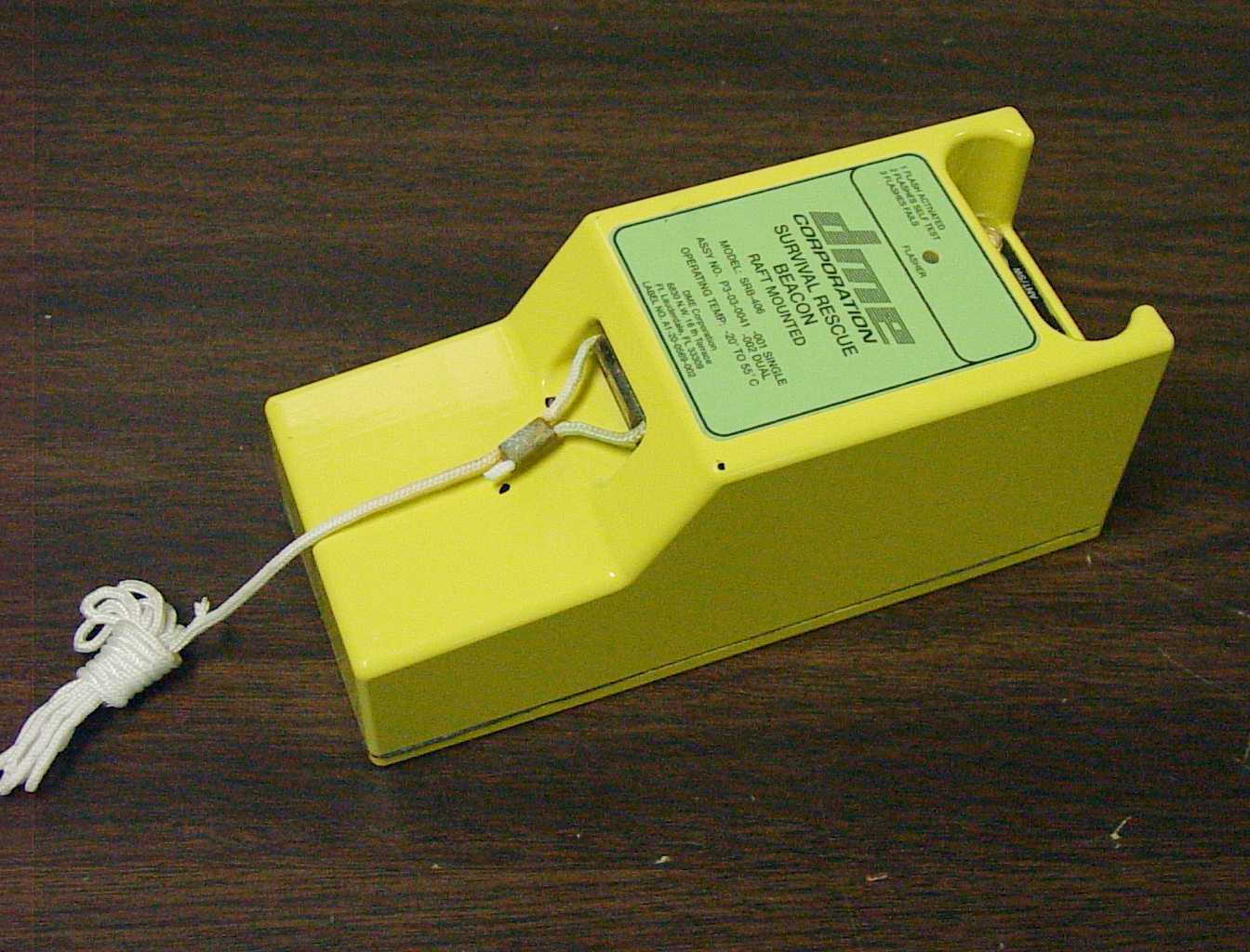
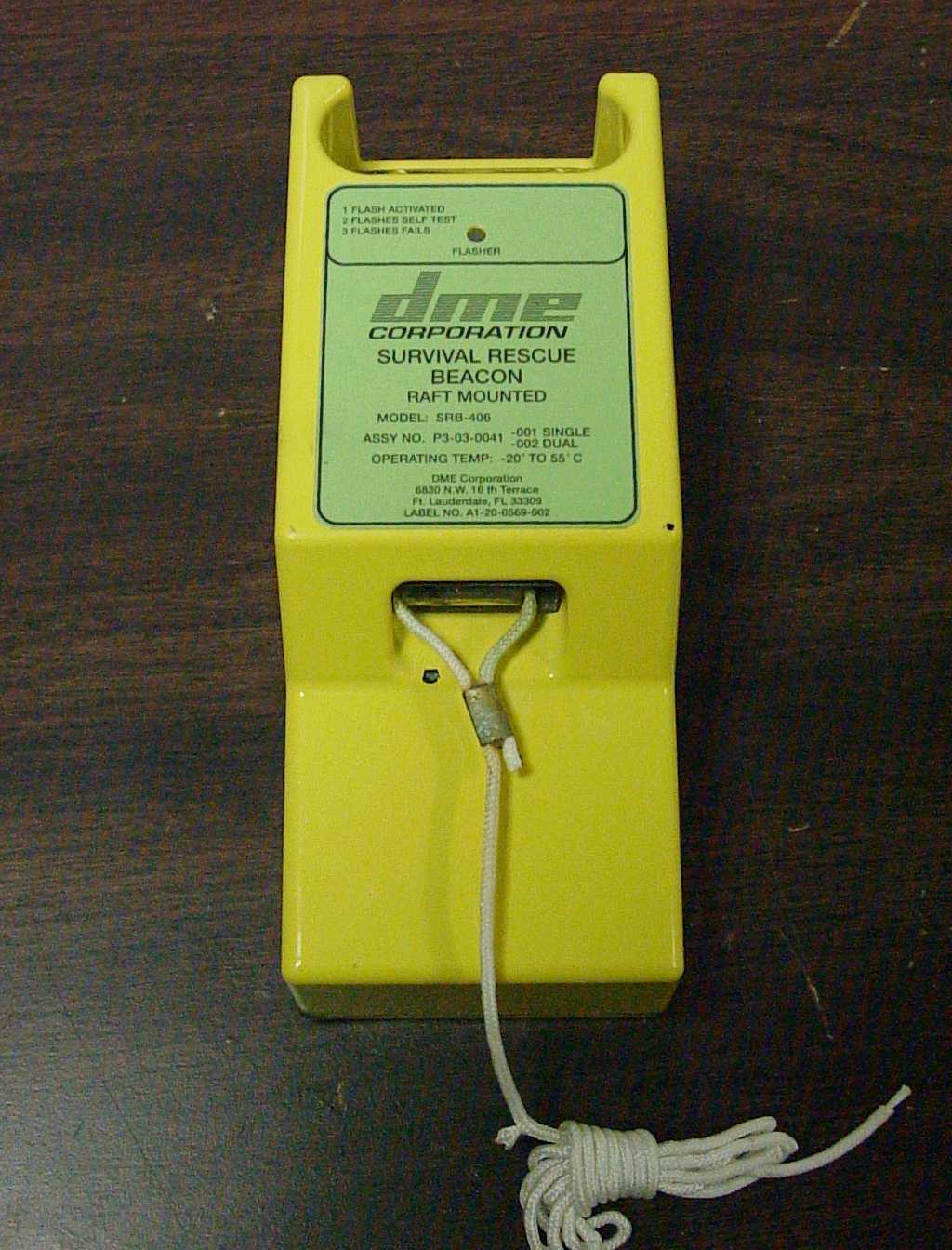
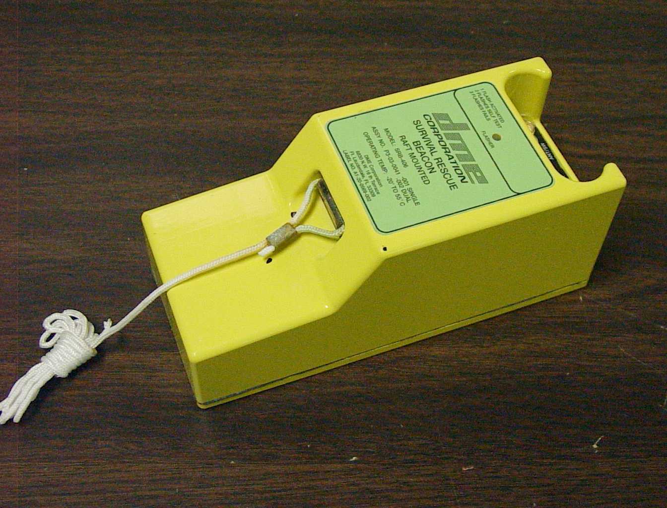
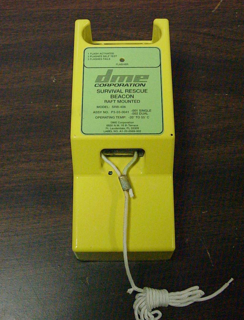
- Survival Rescue Beacon, Raft Mounted
- Frequency Range
- 406.02700000 - 406.02900000
- Country
- United States
Documents & Files
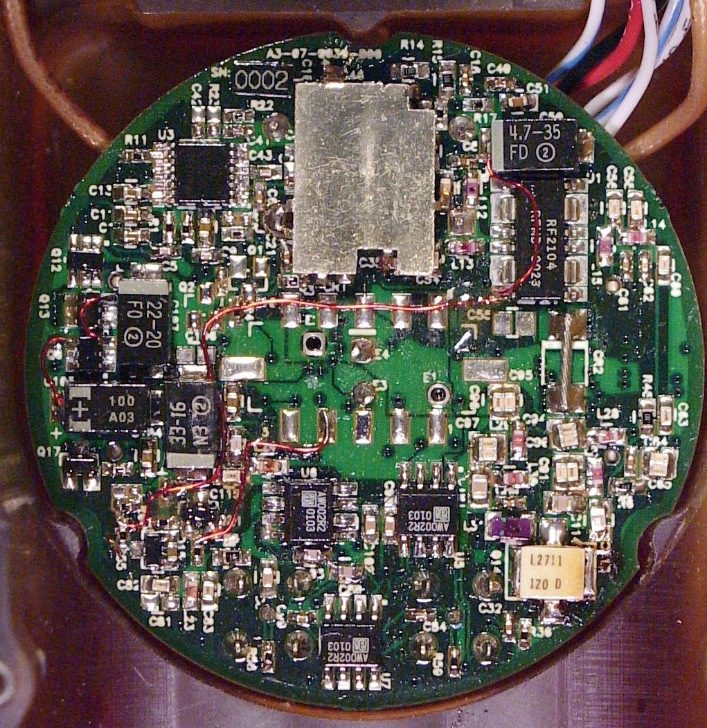
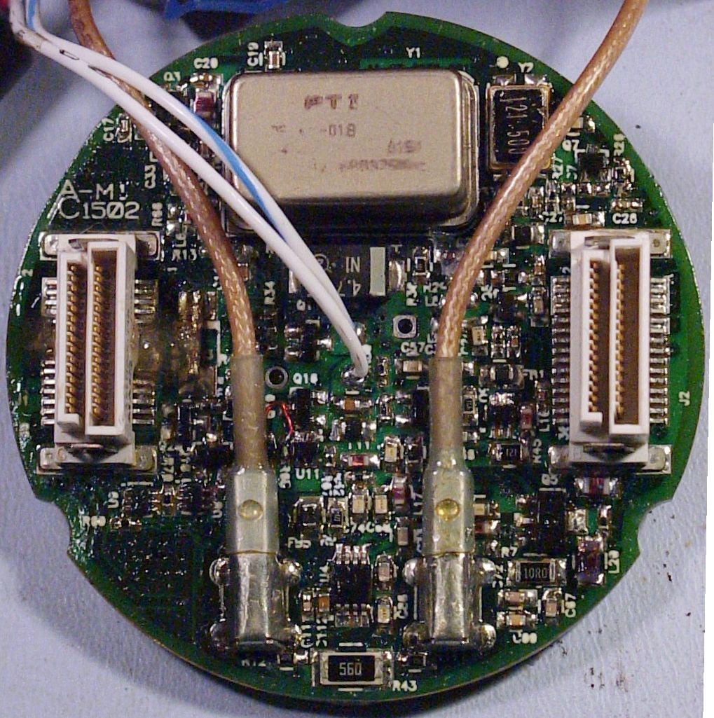
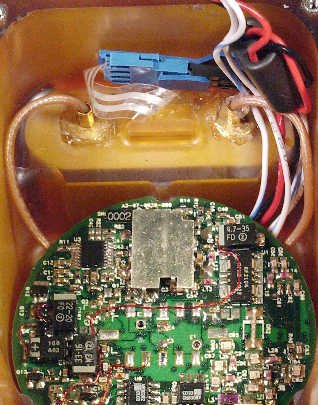
Document Text
Text extracted from the exhibit documents filed with the FCC. Open a document above to read the original.
Users Manual
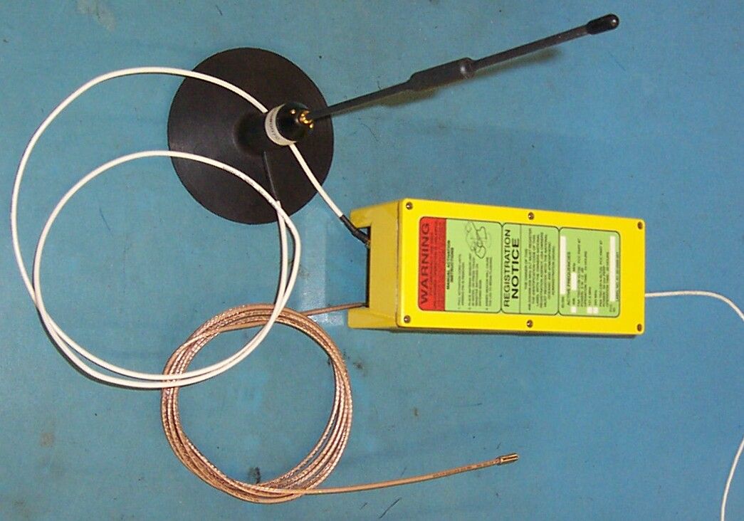
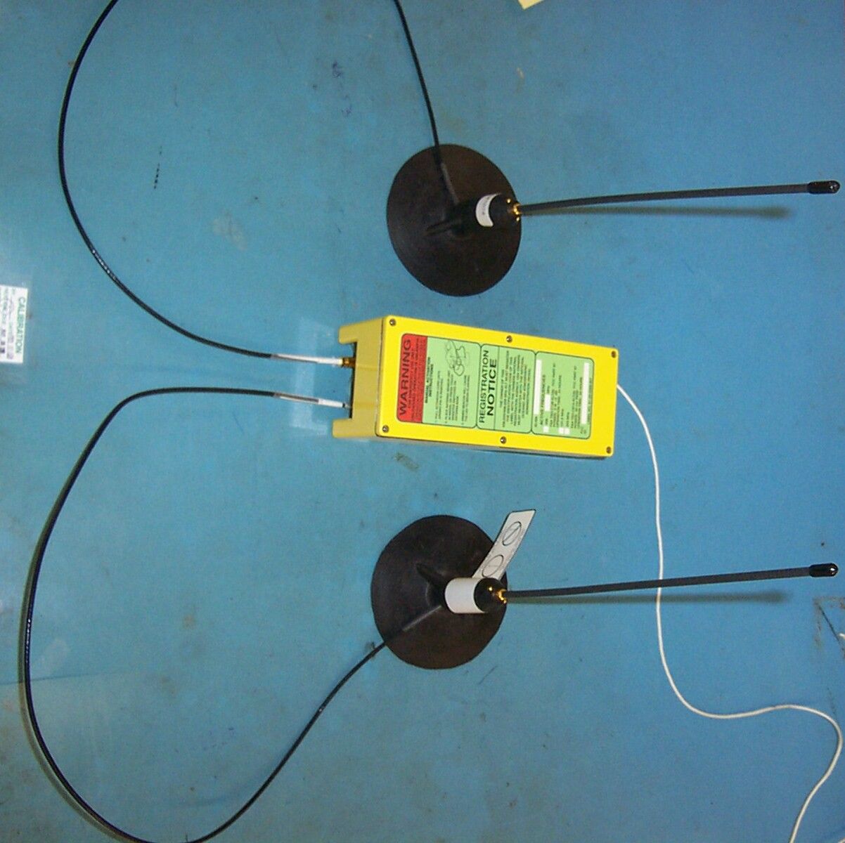
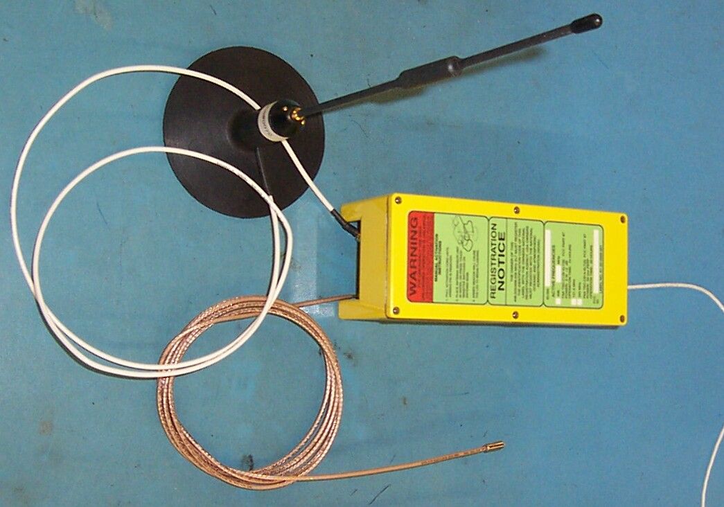
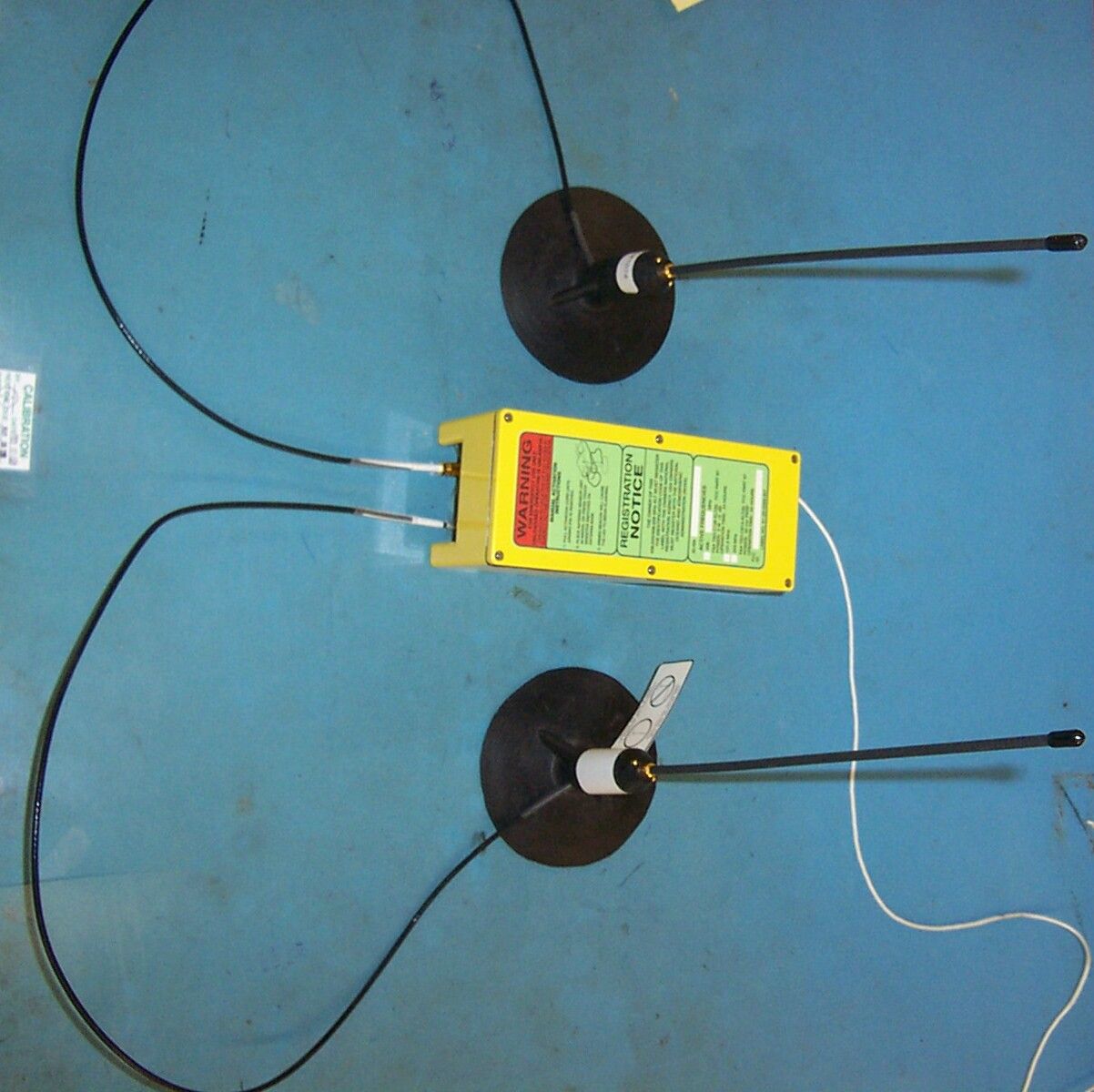
Document No. Y1-06-0130 Rev. B 6830 N.W. 16th Terrace, Fort Lauderdale, FL 33309 (954) 975-2100 *Fax (954) 979-3313 * www.dmecorp.com OPERATION MANUAL for the MODEL SRB-406 TYPE S ELT PN P3-03-0041 Series Where used: P3-03-0041 Series Next assembly: P3-03-0041 Series Y1-06-0130 Prepared by: Don Van Erem Date: September 12, 2002 Checked by: Eric Hiner Date: September 12, 2002 Approved by: Eric Hiner Date: September 12, 2002 Approved by: Phil Pelfrey Date: September 12, 2002 NOTICE IS HEREBY GIVEN THAT ALL DATA CONTAINED IN, REVEALED BY, OR SHOWN IN THIS DOCUMENT ARE PROPRIETARY AND BELONGS TO DME CORP., FT. LAUDERDALE, FLORIDA. IT IS FURNISHED AND RECEIVED IN CONFIDENCE SOLELY FOR INFORMATIONAL PURPOSES OF THE RECIPIENT FOR THE PURPOSES HEREWITH TRANSMITTED. NONE OF THE INFORMATION CONTAINED HEREIN SHALL BE USED FOR ANY OTHER PURPOSES OR DUPLICATED IN WHOLE OR IN PART WITHOUT PRIOR AUTHORIZATION OF DME CORP. Y1-06-0130 Rev. B Page 2 of 9 REVISIONS Revision Date Change Description Approval A 12/19/02 ECO #13565 T. Cohen B 3/21/03 ECO #13724 T. Cohen Y1-06-0130 Rev. B Page 3 of 9 1.0 GENERAL DESCRIPTION The Model SRB-406 Emergency Locator Transmitter (ELT) is a survival-type transmitter manufactured for use on aviation life rafts. The ELT broadcasts on 121.5 MHz, 243.0 MHz, and 406.028 MHz. The SRB-406 is designed for semi-permanent installation in survival raft or raft devices. It features automatic activation when it comes in contact with water and also incorporates a manual activation means for operation on land. There are two models, the -001 and the -002. The -001 single antenna SRB-406 is configured for use on non-reversible, self-righting rafts and the -002 dual antenna SRB-406 is for rafts that are reversible. 2.0 COMPONENT DESCRIPTION AND OPERATION 2.1 Transmitter The transmitter produces a signal for search and rescue when locating survivors of an aircraft accident. The transmitter is automatically activated when the raft is deployed in water. The transmitter may also be manually activated. In the event that the raft is deployed on land, the ELT may be activated manually by touching both of the contacts on the antenna base with moistened fingers. ELT activation is indicated by the flashing light emitting diode (LED) located on the top of the transmitter case. The SRB transmitter is protected inside a tough sealed plastic case. The case is designed to protect the transmitter electronics and battery from external loads encountered in packing the inflatable device. To prevent inadvertent activation in the packed raft, the transmitter features an arming pin and lanyard. The transmitter does not receive battery power until the arming pin is pulled from the transmitter case. The arming pin lanyard is attached on the raft so that the arming pin is pulled automatically upon inflation of the raft system. Once the arming pin is pulled, the unit will begin to transmit as soon as the water activation sensor/antenna(s) is submerged (or the sensors are shorted by means of moistened fingers). Reinstalling the arming pin into the mating clip will cause the unit to cease transmitting. Y1-06-0130 Rev. B Page 4 of 9 -001 Single Antenna Model -002 Double Antenna Model Figure 1. Model SRB-406 I Bilingual Bilingual Y1-06-0130 Rev. B Page 5 of 9 2.2 Arming Pin The arming pin requires a pull force of approximately 8 pounds from an angle of 0 to 60 degrees from the pin axis. The manufacturer of the inflatable device performs attachment of the lanyard to the raft. To activate the transmitter, pull the lanyard until the cylindrical arming pin is removed from the corresponding clip in the transmitter housing. As soon as the arming pin is removed, the unit is ready to transmit. In the case of the -001 single antenna model, to begin transmitting, the antenna sensors must be submerged (or moistened fingers placed across both sensors of the antenna) or the water activation sensor must detect water. With the -002 double antenna model, transmission will begin when the antenna sensors are submerged (or moistened fingers are placed across both sensors of one of the antennas). Inserting the arming pin back into the clip in the transmitter housing will either disallow operation or cause an operational unit to cease transmitting. Transmission has stopped when the LED on the transmitter housing ceases flashing. 2.3 Antenna The antenna(s) is an omni-directional, vertically polarized, whip antenna. The antenna assembly consists of a pliant rubber base and a replaceable flexible whip antenna mounted in a base. The antenna is resonant at 121.5 MHz, 243.0 MHz and 406.028 MHz. The rubber antenna base features activation sensors that operate by water contact or other low resistance contact. The base also incorporates a RF ground plane, which enhances RF transmission when in contact with the raft surface. 2.4 Water Activation Sensor On the -001 model, a second wire lead from the transmitter case terminates in a low resistance water activation sensor. This wire lead is generally mounted so that following normal inflation of the raft, the water activation sensor will be located well below the water line. This sensor lead is detachable from the transmitter. On the -002 model, the water activation sensors are on both antennas. 2.5 Battery Power for the SRB-406 transmitter is provided by a single lithium battery pack that is located within the transmitter housing. The battery pack uses 4 each lithium/manganese dioxide, 1-1/4 “C” size cells. The cells are arranged in series. Each cell is protected from short circuit by a manufacturers installed safety device (PTC). Y1-06-0130 Rev. B Page 6 of 9 The maximum storage temperature range for the battery pack is –20 0 C to +40 0 C. The maximum installation temperature range is -55 0 C to +85 0 C. At temperatures above 91 0 C the battery pack is subject to venting. Battery Pack General Precautions • Temperatures near the melting point of the lithium metal (180 0 C) will result in a lithium f…
Text truncated - open the document above for the full version.
Attestation Statements
WHEREAS, DME Corporation of Fort Lauderdale, USA , the manufacturer of a 406 Megahertz Distress Beacon packaged as an ELT , and identified as Model: SRB-406-001 1) or SRB-406-002 2) has submitted test data an d had said beacon tested in September 2002 - February 2003 at a facility accepted by Cospas-Sarsat at EPG, Fort Huachuca, USA , to demonstrate that said beacon meets the applicable technical requirements for use with the Cospas-Sarsat Satellite System, as defined in documents C/S T.001”, Issue 3 - Rev. 3, October 1999, and C/S T.007 “Cospas-Sarsat 406 MHz Distress Beacon Type Approval Standard”, Issue 3 - Rev. 8, October 2001, 3) for frequency channel 406.028 MHz; WHEREAS, the Cospas-Sarsat Counc il has determined, following a review of the test results, that the said beac on meets the Cospas-Sarsat Class 2 requirements and is rated for operating over the temperature range of -20 ° C to +55 ° C , 4) with battery: DME PN P4-03-0001 (U2560HCES) Lithium Manganese Dioxide (LiMnO 2 , 4 X 5/4C-cells) and WHEREAS, said manufacturer has cer tified that all other units of the same type will meet said technical requirements in a sim ilar manner to the un it subjected to test, which incorporated the following features: - 121.5 and 243MHz Auxiliary radio locating devices (50 mW, intermittent, duty cycle 40%) - Automatic Activation on contact with water or manual activation on land - Self-test mode (no radiation) 1) with single triple frequency antenna for installation on non reversible life raft with 36” coaxial cable 2) with dual triple frequency antenna for inst allation on reversible life raft or slide/rafts with 36” coaxial cable 3) beacon is approved for use with short format user protocol 4) specified operating lifetime:406 MHz - 24 hours, 121.5 MHz - 48 hours NOW, THEREFORE , in reliance upon the follo wing, the Cospas-Sarsat Council does hereby certify that the 406 MHz Distress Beacon Model identified herein is compatible with the Cospas-Sarsat System as of the date of this Certificate. Certificate No: 133 ( Valid until 3 February 2005) Date: 3 February 2003 Signed by: D. Levesque Head of Cospas-Sarsat Secretariat NOTE, HOWEVER: 1. This certificate does not authorize the operation or sale of any 406 MHz distress beacon. Such authorization may require type acceptance by national administrations in countries where the beacon will be distributed, and may also be subject to national licensing requirements. 2. This certificate is intended only as a formal notification to the above identified manufacturer that the Cospas-Sarsat Council has determined, on the basis of test data of a beacon submitted by the manufacturer, that 406 MHz distress beacons of the type identified herein meet the standards for use with the Cospas-Sarsat System. This certificate is not a warranty and Cospas-Sarsat hereby expressly disclaims any and all liability arising out of or in connection with the i ssuance, use, or misuse of this certificate. 3. This certificate is subject to revocation by the Cospas-Sarsat Council should the beacon type for which it is issued cease to meet the Cospas-Sarsat specification. A new certificate may be issued after satisfactory corrective action has been taken and correct performance demonstrated in accordance with to the Cospas-Sarsat Type Approval Standard. COSPAS-SARSAT TYPE APPROVAL CERTIFICATE For a 406 Megahertz Distress Beacon for use with the Cospas -Sarsat Satellite System
Attestation Statements
6830 N.W. 16th Terrace, Fort Lauderdale, FL 33309-1518 (954)975-2100 • Fax (954)979-3313 • www.dmecorp.com 23 April, 2002 Letter of Attestation (KTF406-ELT) In accordance with the FCC Rules and Regulations regarding the Application of Equipment Authorization, DME Corporation attests to compliance with all testing methods and measurements required by the FCC, FAA and COSPAS-SARSAT for Emergency locator Transmitters (ELT). Submitted as verification of this testing are the necessary test reports and the Type Approval Certificate (TAC 133) from COSPAS-SARSAT. FAA approval is expected within the next thirty days and will be submitted upon request from the FCC Laboratories. Sincerely, Michael Wooster Program Manager, DME Corporation
Attestation Statements
6830 N.W. 16th Terrace, Fort Lauderdale, FL 33309-1518 (954)975-2100 • Fax (954)979-3313 • www.dmecorp.com Request for Confidentiality (KTF406-ELT) In accordance with the FCC Rules and Regulations, 47CFR0.459, DME Corporation requests that portions of the material submitted for Type Approval of the 406MHz Emergency Locator Transmitter (KTF406-ELT) remain confidential. This request is made due to the unique design and performance of the above listed ELT. The DME 406MHz Emergency Locator Transmitter (406 ELT) is uniquely designed for installation and automatic deployment into both General Aviation and Commercial life rafts and slide rafts. The housing was specifically designed to meet these needs. Subsequently, the circuitry of the 406 ELT is unique to this design. Therefor, disclosure of identified material would result in substantial competitive harm to DME Corporation. As DME Engineering incurred significant expenses in cost, time and effort to produce this design, it is DME’s request that this information remains confidential. The corresponding documents to this request have either been separated or marked accordingly. These documents include drawings, schematics and technical manuals related to the 406 ELT. Sincerely, Michael Wooster Program Manager, DME Corporation
Cover Letter(s)
From: Michael Wooster, Program Manager, DME Corporation To: Andy Leimer, Federal Communications Commission Subj: KTF406-ELT 1. In response to FCC correspondence 6/20/02 regarding the KTF406-ELT and it’s occupied bandwidth and frequency designations, the following is submitted: 2. The 242 Mhz designation is in error. Do to an incorrect mathematical calculation, the frequency range listed was incorrect. The correct designation should be 243.0 +/- .012, which would be 242.988 MHz. 3. The bandwidth designation for the 121.5 MHz frequency should be as you stated 3K20A3X. 4. The Bandwidth designation for the 406.025 MHz frequency should also be as you stated, 16K0G1D
Cover Letter(s)
From: Michael Wooster, Program Manager, DME Corporation To: Andy Leimer, Federal Communications Commission Subj: KTF406-ELT 1. In response to FCC correspondence 6/20/02 regarding the KTF406-ELT and it’s occupied bandwidth and frequency designations, the following is submitted: 2. The 242 Mhz designation is in error. Do to an incorrect mathematical calculation, the frequency range listed was incorrect. The correct designation should be 243.0 +/- .012, which would be 242.988 MHz. 3. The bandwidth designation for the 121.5 MHz frequency should be as you stated 3K20A3X. 4. The Bandwidth designation for the 406.025 MHz frequency should also be as you stated, 16K0G1D
Cover Letter(s)
6830 N.W. 16th Terrace, Fort Lauderdale, FL 33309 (954) 975-2100 * Fax (954) 979-3313 * www.dmecorp.com July 2, 2003 Federal Aviation Administration Mr. Mario Jimenez, ASR-100 NISC 800 Independence Avenue, S.W. Washington, DC 20591 Dear Mr. Jimenez, As required by 47CFR87.147, please accept this as a Letter of Coordination for DME Corporation’s 406 MHz Emergency Locator Transmitter (KTF406-ELT). The specific equipment discussed is a Type “S” Emergency Locator Transmitter, which operates on the 121.5 and 243.0 MHz Homer frequency, and 406.028 MHz. Currently DME has Cospas-Sarsat Type Approval for this beacon and is in the process of obtaining FAA TSO C-126 certification (we expect that certification within a week). Description The Model SRB-406 Emergency Locator Transmitter (ELT) is a survival-type transmitter manufactured for use on aviation life rafts. The ELT broadcasts on 121.5 MHz, 243.0 MHz, and 406.028 MHz. Emissions Type/Rated Power Output 121.5 MHz Output Power: 50mw Emission Designator: 3K20A3X Frequency Tolerance: 50ppm Frequency Range: 121.494 – 121.506 MHz 243.0 MHZ Output Power: 50mw Emission Designator: 3K20A3X Frequency Tolerance: 50ppm Frequency Range: 242.988 – 243.012 MHz 406.028 MHz Output Power: 5w Emission Designator: 16KOG1D Frequency Tolerance: 17.115 ppm Frequency Range: 406.027 – 406.029 MHz Antenna Characteristics The antenna(s) is an omni-directional, vertically polarized, whip antenna. The antenna assembly consists of a pliant rubber base and a replaceable flexible whip antenna mounted in a base. The antenna is resonant at 121.5 MHz, 243.0 MHz and 406.028 MHz. The rubber antenna base features activation sensors that operate by water contact or other low resistance contact. The base also incorporates a RF ground plane, which enhances RF transmission when in contact with the raft surface. If there is any further information you require, you can reach me at 954-975-2136. Please feel free to contact me at your convenience. Sincerely yours, DME Corporation Michael Wooster Program Manager
Cover Letter(s)
6830 N.W. 16th Terrace, Fort Lauderdale, FL 33309-1518 (954)975-2100 • Fax (954)979-3313 • www.dmecorp.com July 2, 2003 Federal Communications Commission Mrs. Juanice Green 445 12th Street, SW Washington, DC 20554 Dear Mrs. Green, In reference to the payment required for our submission to the FCC, DME had originally submitted a hard copy of our application and data package, which was rejected due to the FCC requirement to receive only electronic application material. Included with this hard copy was our check for both the FCC approval and confidentiality. Apparently, from both your records and ours, that check was not received or processed. DME will be resubmitting the form 159 as well as the fees associated with this application immediately. I will inform both you and Mr. Leimer when the form has been submitted via the web site. Thank you for your time and patience. Sincerely, Michael Wooster Program Manager DME Corporation
ID Label/Location Info
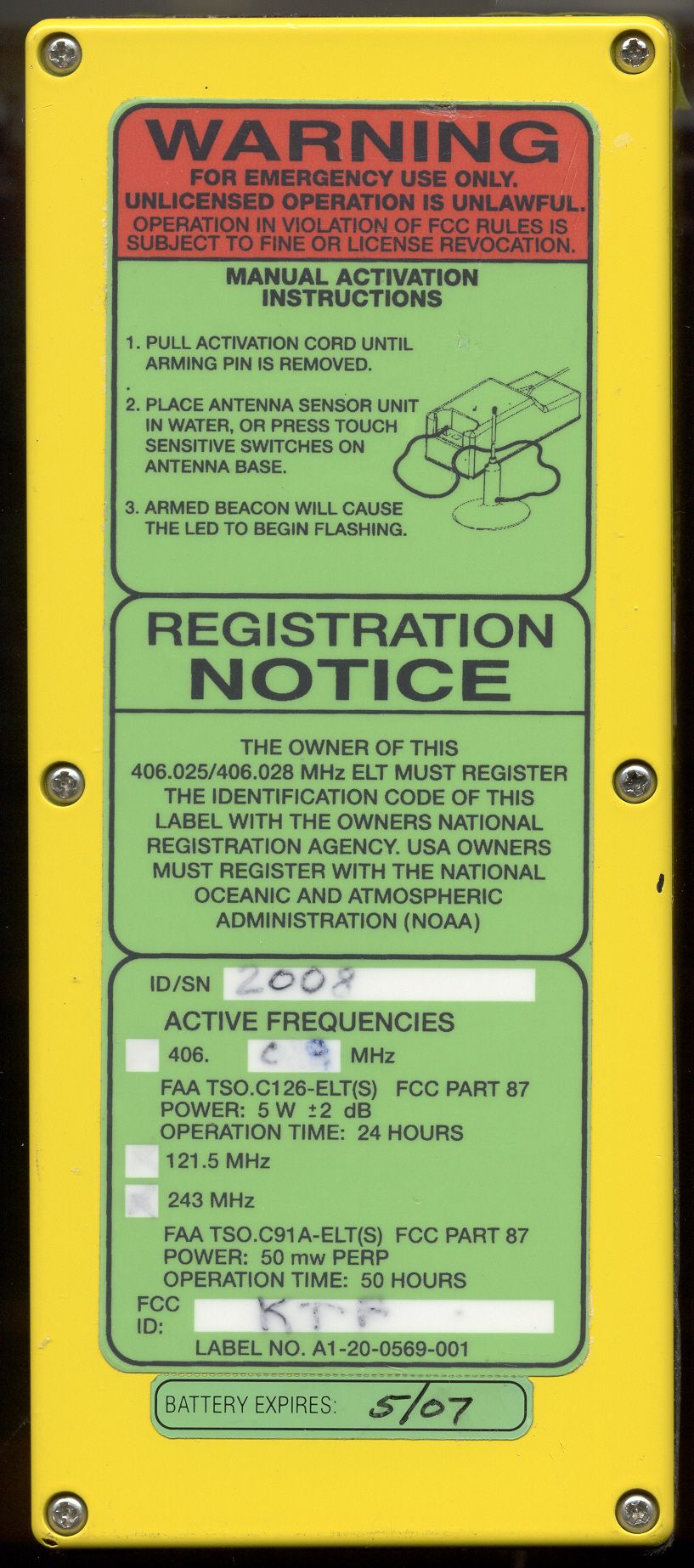
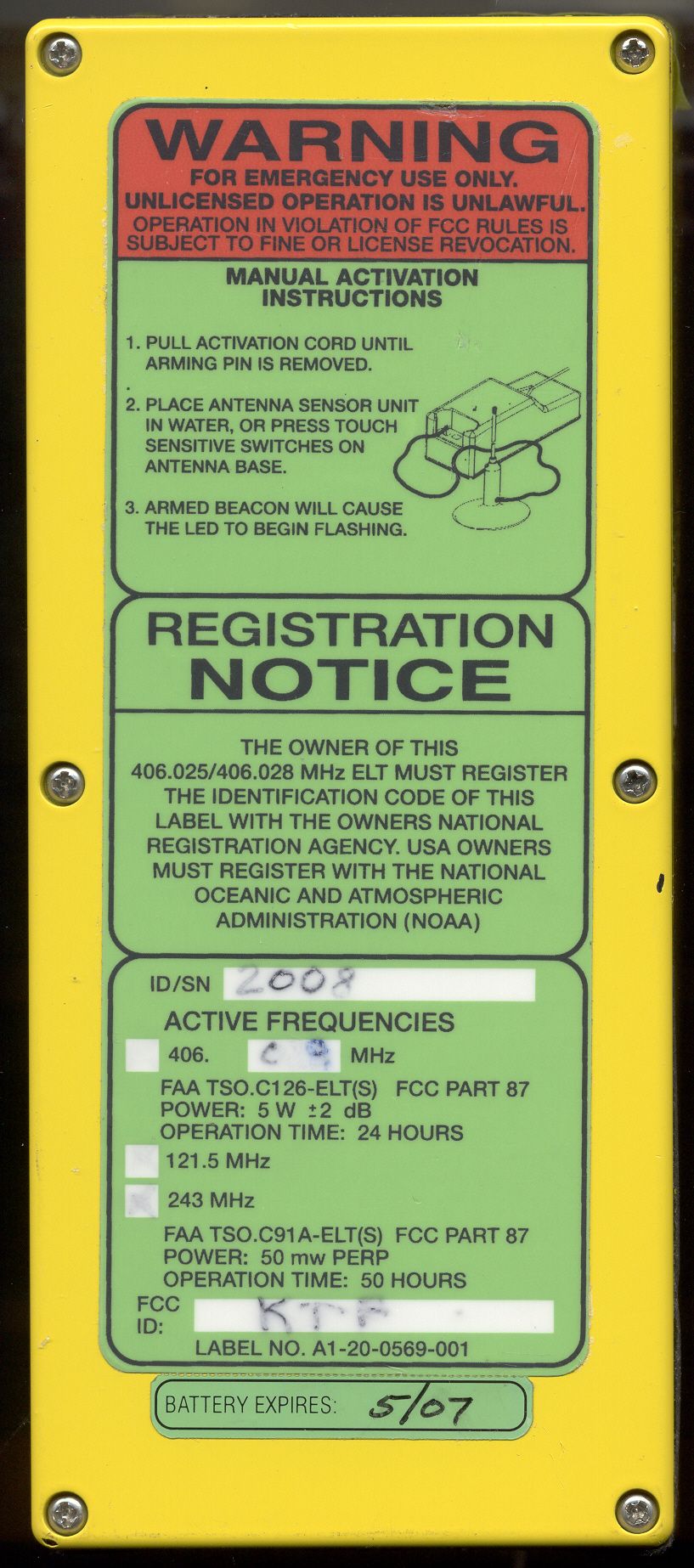
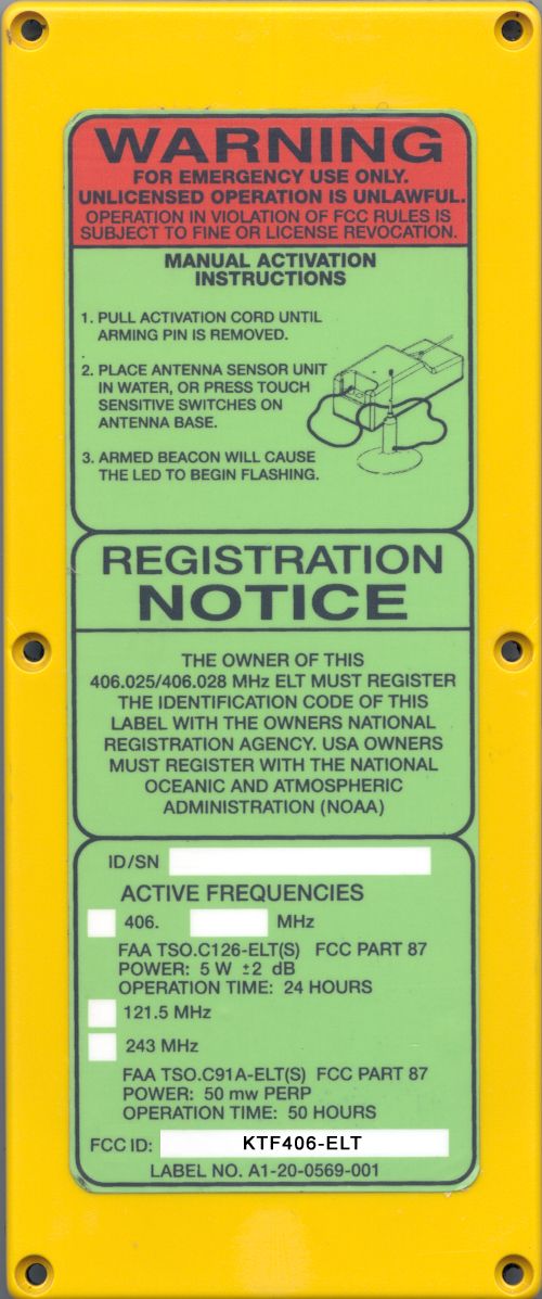
UNLICENSED OPERATION IS UNLAWFUL. FOR EMERGENCY USE ONLY.
ID Label/Location Info
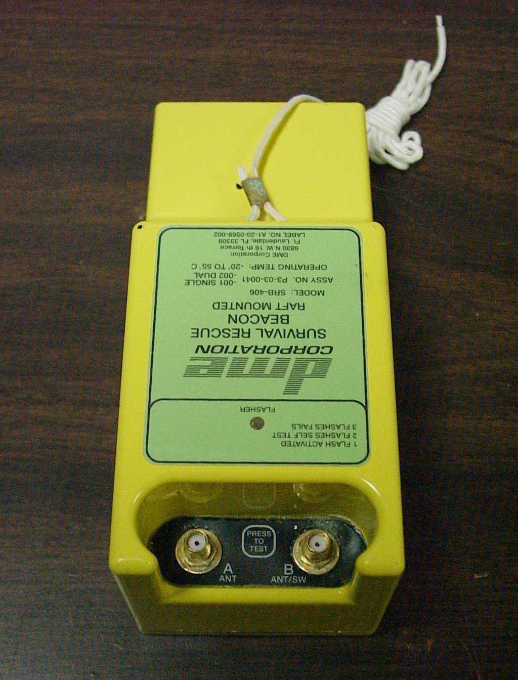
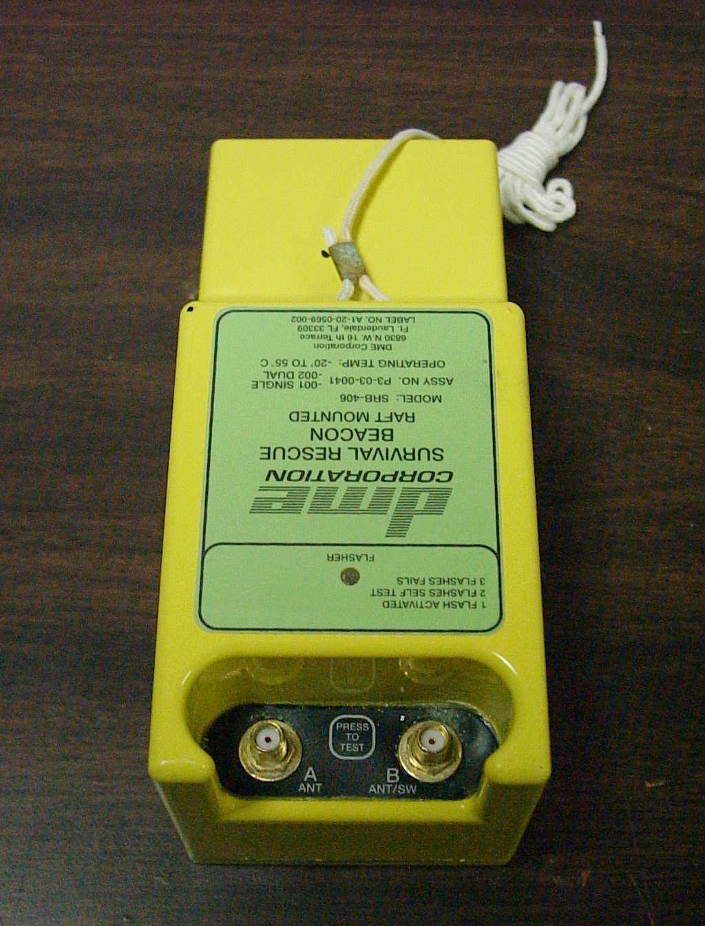
A ANT B ANT/SW PRESS TEST TO
Test Report
Document No. Y3-03-0726 Rev. - 6830 N.W. 16th Terrace, Fort Lauderdale, FL 33309 (954) 975-2100 *Fax (954) 979-3313 * www.dmecorp.com TEST REPORT for EMERGENCY LOCATOR TRANSMITTER (ELT) SURVIVAL TYPE – ELT (S) 121.5 MHz, 243.0 MHz and 406.028 MHz FAA TSO C126 and TSO C91a Y3-03-0726 Prepared by: B.DIAS Date: 3/27/03 Checked by: J.COMBARIZA Date: 3/27/03 Approved by: E.HINER Date: 3/27/03 Approved by: T.COHEN Date: 3/27/03 NOTICE IS HEREBY GIVEN THAT ALL DATA CONTAINED IN, REVEALED BY, OR SHOWN IN THIS DOCUMENT ARE PROPRIETARY AND BELONGS TO DME CORP., FT. LAUDERDALE, FLORIDA. IT IS FURNISHED AND RECEIVED IN CONFIDENCE SOLELY FOR INFORMATIONAL PURPOSES OF THE RECIPIENT FOR THE PURPOSES HEREWITH TRANSMITTED. NONE OF THE INFORMATION CONTAINED HEREIN SHALL BE USED FOR ANY OTHER PURPOSES OR DUPLICATED IN WHOLE OR IN PART WITHOUT PRIOR AUTHORIZATION OF DME CORP. Y3-03-0726 Rev. - Notice is hereby given that all data contained in, revealed by, or shown in this document are proprietary and belongs to DME Corp., Ft. Lauderdale, Florida. Please see cover sheet for full statement. Page 2 of 64 REVISIONS Revision Date Change Description Approval - 3/27/03 ECO #13738 T.COHEN Y3-03-0726 Rev. - Notice is hereby given that all data contained in, revealed by, or shown in this document are proprietary and belongs to DME Corp., Ft. Lauderdale, Florida. Please see cover sheet for full statement. Page 3 of 64 1.0 PURPOSE AND OBJECTIVE This test report describes the inspections and tests performed to demonstrate that the Model SRB-406 survival type ELT beacon (transmitter, antennas and battery pack) meets the minimum performance standards defined by FAA technical standard order (TSO) C126 and TSO C91a. 2.0 SCOPE This test report describes the inspections and tests performed on a survival type ELT, beacon (PN P3-03-0041 series) that consists of a RF/Digital printed wiring assembly (PN A3-07-1032 series), antennas (PN P3-03-0040-001), lanyard assembly (P3-03- 0042-001) and a lithium battery pack (PN P4-03-0001-001). The beacon operates on 121.5 MHz, 243.0MHz and 406.028 MHz. This beacon has a water sensor and does not contain a crash sensor. 3.0 EXCEPTIONS/LIMITATIONS 3.1 Test and Configuration Exceptions Exceptions to the requirements of RTCA DO-204 are noted below. These exceptions are in addition to the waivers requested within the qualification test plan (Y3-02-0506). • The Model SRB-406 ELT is not buoyant. The ELT is mounted to inflatable structures, such as life rafts or evacuation slide/rafts, used on commercial and general aviation airplanes and does not require a buoyancy provision. Reference: RTCA DO-204, paragraph 2.1.15. • The Model SRB-406 ELT does not have a tether. The ELT is mounted to inflatable structures, such as life rafts or evacuation slide/rafts, used on commercial and general aviation airplanes and does not require a tether provision. Reference: RTCA DO-204, paragraph 2.1.15. • The Model SRB-406 ELT is not designed to meet the impact test of RTCA DO-204, paragraph 2.3.4.2. The ELT is mounted to inflatable structures, such as life rafts or evacuation slide/rafts, used on commercial and general aviation airplanes and is protected from impact since it is stowed within and encapsulated by the fabric of the de-inflated life raft structure during emergency landings. Reference: RTCA DO-204, paragraph 2.3.4.2 and Table 2-2, page 33. • The Model SRB-406 ELT water sensor (P3-03-0043) was not included in the environmental test sequences. The water sensor assembly uses the same materials and similar assembly processes as the triple frequency antenna but is functionally less complex (no electronic circuitry). The water sensor assembly mechanism consists of a metal contact, electrically connected to the cable and insulated from Y3-03-0726 Rev. - Notice is hereby given that all data contained in, revealed by, or shown in this document are proprietary and belongs to DME Corp., Ft. Lauderdale, Florida. Please see cover sheet for full statement. Page 4 of 64 the center conductor such that any water or fluid that bridges the insulated contacts will form a circuit and activate the unit after it is armed. The units under test were physically configured as dual antenna ELTs (P3-03-0041-002), with the second antenna acting as the water sensor. • The units under test were programmed to operate as single antenna/water sensor ELT (P3-03-0041-001). • Verification that the Model SRB-406 ELT met performance standards (after exposure to environmental conditions) was deferred after certain environmental tests. This action was taken in order to shorten test schedule. The mechanical/functional characteristics of the unit under test were verified prior to continuing the environmental testing. • The Model SRB-406 ELT decompression test was not performed per RTCA DO-204 or Eurocae ED-62. The flight crew does not activate the Model SRB-406 beacon after a decompression event has occurred at altitude. The Model SRB-406 ELT is not designed to be activated in flight but after an inflatable is deployed. The beacon was subjected to the decompression event but was activated at ambient pressure. • Design changes were incorporated into the beacon design after the test configuration was defined and after testing began. These design changes were incorporated as a result of anticipated or actual product difficulties. Design changes that were incorporated into the beacon as a result of anticipated or actual product difficulties are described in an Engineering report provided as Attachment A or in specific failure analysis reports. • Engineering design changes were physically incorporated into the RF and digital printed wiring assemblies using non-standard assembly processes and representative conductors (piggybacked components, jumper wires, etc.) prior to initiation of the qualification testing. The RF and digital printed wiring assemblies were electrically representative of the engineering design intent but did not physically represen…
Text truncated - open the document above for the full version.
Test Report
Document No. Y3-02-0530 Rev. - 6830 N.W. 16th Terrace, Fort Lauderdale, FL 33309 (954) 975-2100 *Fax (954) 979-3313 * www.dmecorp.com ENGINEERING REPORT for QUALIFICATION TESTING DESIGN CHANGES MODEL SRB-406 Where used: Model SRB-406 Type S ELT Next assembly: P3-03-0041 Series Y3-02-0530 Prepared by: Eric Hiner Date: 2/25/03 Checked by: Jorge Combariza Date: 2/25/03 Approved by: Eric Hiner Date: 2/25/03 Approved by: Tracey Cohen Date: 2/26/03 NOTICE IS HEREBY GIVEN THAT ALL DATA CONTAINED IN, REVEALED BY, OR SHOWN IN THIS DOCUMENT ARE PROPRIETARY AND BELONGS TO DME CORP., FT. LAUDERDALE, FLORIDA. IT IS FURNISHED AND RECEIVED IN CONFIDENCE SOLELY FOR INFORMATIONAL PURPOSES OF THE RECIPIENT FOR THE PURPOSES HEREWITH TRANSMITTED. NONE OF THE INFORMATION CONTAINED HEREIN SHALL BE USED FOR ANY OTHER PURPOSES OR DUPLICATED IN WHOLE OR IN PART WITHOUT PRIOR AUTHORIZATION OF DME CORP. Y3-02-0530 Rev. - Notice is hereby given that all data contained in, revealed by, or shown in this document are proprietary and belongs to DME Corp., Ft. Lauderdale, Florida. Please see cover sheet for full statement. Page 2 of 16 REVISIONS Revision Date Change Description Approval - 2/26/03 ECO # 13666 T.Cohen Y3-02-0530 Rev. - Notice is hereby given that all data contained in, revealed by, or shown in this document are proprietary and belongs to DME Corp., Ft. Lauderdale, Florida. Please see cover sheet for full statement. Page 3 of 16 1.0 PURPOSE This report describes the design changes implemented in the Model SRB-406 Type S Emergency Locator Transmitter, PN P3-03-0041-002, and all lower tier sub-assemblies, before, during and after the performance of the FAA TSO C91a and TSO C126 qualification testing. 2.0 SCOPE This report is applicable to test articles and specimens tested per Engineering Test Plan Y3-02-0506 and the test results documented within Engineering Test Report Y3-03-0726. The original test article and test specimen configurations are as described in Engineering Test Report Y3-03-0726. 3.0 REFERENCE DOCUMENTS Federal Aviation Administration Technical Standard Order TSO-C126, 406 MHz Emergency Locator Transmitter (ELT), dated December 23, 1992. Technical Standard Order TSO-C91a, Emergency Locator Transmitter (ELT) Equipment, dated April 29, 1985. DME Corporation Engineering Drawing P3-03-0041, Revision (-), SRB-406 Beacon. Engineering Test Plan, Y3-02-0506, Revision (-), Design Qualification Test Plan/Procedure for the SRB-406 ELT. Engineering Test Report, Y3-03-0726, Revision (-), Test Report for Emergency Locator Transmitter (ELT), Survival Type – ELT (S), 121.5 MHz, 243.0 MHz and 406.028 MHz, FAA TSO C126 and TSO C91a. 4.0 DESIGN CHANGES This section describes the design changes that were incorporated into the initial test article configuration as design improvements and difficulties were discovered before and after the start of qualification testing. This section also describes design changes that are currently documented in the design data but have not been incorporated into the qualification test articles and test Y3-02-0530 Rev. - Notice is hereby given that all data contained in, revealed by, or shown in this document are proprietary and belongs to DME Corp., Ft. Lauderdale, Florida. Please see cover sheet for full statement. Page 4 of 16 specimens. These design changes were not exposed to the environmental test conditions defined within Engineering Test Plan Y3-02-0506. Design changes were incorporated into the transmitter housing, transmitter cover, transmitter cover gasket, transmitter assembly, membrane switch and triple frequency antenna. The design changes are described in the following paragraphs. 4.1 Antenna /Transmitter SMA Connector Sealing Description of the Design Difficulty The length of the SMA connector, combined with the attachment hardware dimensional stack-up and the “D” opening wall thickness exposed insufficient threads for the antenna right angle SMA connector to seal with the transmitter straight SMA connector body. The wall thickness of the transmitter housing was found to be too thick for proper sealing of the mated SMA connectors. This design difficulty was resolved by eliminating the sealing washer from the attachment hardware stack-up and sealing the opening with an RTV adhesive/sealant. All test articles started qualification testing in this configuration. Tests Performed with the Initial Test Configuration The transmitter straight SMA connector (w/o sealing washer, w/RTV sealant) installed in a transmitter housing with a “D” opening wall thickness of 0.125 inches (nominal) was exposed to the low temperature activation, high temperature activation, altitude, decompression, overpressure, vibration, humidity and spray proof test conditions without failure. A delay in the testing schedule created an opportunity to incorporate a new transmitter housing with the proper “D” opening wall thickness (0.070 inches, nominal). The initial test configuration was modified by introducing a new housing with the correct “D” opening wall thickness and the balance of the testing completed with the new housing. Tests Performed with the New Test Configuration The transmitter straight SMA connector (w/o sealing washer, w/RTV sealant) installed in a transmitter housing with a “D” opening wall thickness of 0.070 inches (nominal) was exposed to the spray proof, salt water immersion, sand and dust, salt spray (corrosion), operational shock, crashworthiness, crush, flame and post-crash immersion test conditions without failure. Justification for Accepting Test Results The change in wall thickness improves the ability of the design to withstand the environmental conditions. Y3-02-0530 Rev. - Notice is hereby given that all data contained in, revealed by, or shown in this document are proprietary and belongs to DME Corp., Ft. Lauderdale, Florida. Please see cover sheet for full statement. Page 5 of 16 Action Taken The sealing washer has been removed from the design and the wall thickness has …
Text truncated - open the document above for the full version.
Test Report
Document No. Y3-02-0506 Rev. - 6830 N.W. 16th Terrace, Fort Lauderdale, FL 33309 (954) 975-2100 *Fax (954) 979-3313 * www.dmecorp.com DESIGN QUALIFICATION TEST PLAN/PROCEDURE for the SRB-406, 406MHz EMERGENCY LOCATOR TRANSMITTER Next Assembly: P3-03-0041 Series Where used: Model SRB-406 Y3-02-0506 Prepared by: W. C. Janzer Date: 3/1/03 DER No. DERT-510187-CE Checked by: J. Combariza Date: 3/21/03 Approved by: Eric Hiner Date: 3/21/03 Approved by: T. Cohen Date: 3/21/03 NOTICE IS HEREBY GIVEN THAT ALL DATA CONTAINED IN, REVEALED BY, OR SHOWN IN THIS DOCUMENT ARE PROPRIETARY AND BELONGS TO DME CORP., FT. LAUDERDALE, FLORIDA. IT IS FURNISHED AND RECEIVED IN CONFIDENCE SOLELY FOR INFORMATIONAL PURPOSES OF THE RECIPIENT FOR THE PURPOSES HEREWITH TRANSMITTED. NONE OF THE INFORMATION CONTAINED HEREIN SHALL BE USED FOR ANY OTHER PURPOSES OR DUPLICATED IN WHOLE OR IN PART WITHOUT PRIOR AUTHORIZATION OF DME CORP. Y3-02-0506 Rev. - Notice is hereby given that all data contained in, revealed by, or shown in this document are proprietary and belongs to DME Corp., Ft. Lauderdale, Florida. Please see cover sheet for full statement. Page 2 of 11 REVISIONS Revision Date Change Description Approval - 3/21/03 ECO #13719 T.COHEN Y3-02-0506 Rev. - Notice is hereby given that all data contained in, revealed by, or shown in this document are proprietary and belongs to DME Corp., Ft. Lauderdale, Florida. Please see cover sheet for full statement. Page 3 of 11 1.0 INTRODUCTION The DME SRB-406 Emergency Locator Transmitter is a distress beacon that is intended to be attached to various types of life rafts aboard U.S. registered civil airplanes. The 406.028 MHz Emergency Locator Transmitter also contains a homing beacon that transmits at 121.5 MHz and 243 MHz. Emergency Locator Transmitters that are used aboard U.S. registered civil airplanes must meet the minimum performance standards prescribed by the Federal Aviation Administration and the Federal Communications Commission. 2.0 PURPOSE The purpose of this document is to identify the test procedures used to demonstrate that the DME model SRB-406 Type S Emergenc…
Text truncated - open the document above for the full version.
Contact Information
Applicant
Todd Marshall(Manager)
Technical Specifications
| # | Rule Parts | Frequency Range | Power Output | Emission | Tolerance |
|---|---|---|---|---|---|
| 3 | 87 | 406.027 MHz - 406.029 MHz | 5 W | 16KOG1D | 17.115 ppm |
Other Applications from Astronics Luminescent Systems Inc

KTFPLB-110
May 27, 2012Personal Locator Beacon
Equipment Class
PLB - Personal Locator BeaconsKTFG1-18-0000
Sep 19, 1994TNB - Licensed Non-Broadcast Station Transmitter
Equipment Class
TNB - Licensed Non-Broadcast Station TransmitterKTFSRB-ELT
Oct 03, 1993TNB - Licensed Non-Broadcast Station Transmitter
Equipment Class
TNB - Licensed Non-Broadcast Station Transmitter