KUJCE10705Ceiling Fan Remote Controller (Transmitter)
Chungear Industrial Co Ltd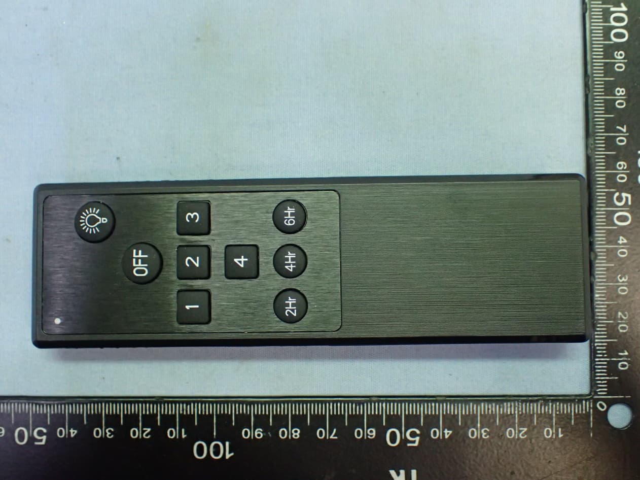
Click to zoom
Application Details
- Equipment Class
- DSC - Part 15 Security/Remote Control Transmitter
- Date of Grant
- Apr 11, 2020
- Application Purpose
- Original Equipment
- Date of Application
- Apr 11, 2020
- Equipment Note
- Ceiling Fan Remote Controller (Transmitter)
- Frequency Range
- 304.25000000 - 304.25000000
- Company
- Chungear Industrial Co Ltd
- Country
- Taiwan
Documents & Files
Document Text
Text extracted from the exhibit documents filed with the FCC. Open a document above to read the original.
Users Manual
CEILING FAN REMOTE CONTROLLER OPERATION AND INSTALLATION INSTRUCTIONS (Please keep this instruction pamphlet.) HANDSET TRANSMITTER OPERATION Activating the Learning process: Turn on the receiver power, press and hold the LEARN key (on the back ofthe transmitter) for 1~3S. Refer to FIG. 2 Light (if installed) will flash twice and off. This confirms that the learing setting is active and ok. Transmitter use 2 pcsAAA/1.5V batteries. LIGHT FUNCTION SELECT SWITCH If the ceiling fan has fluorescent lighting, please slide the “light function select switch” to “O” position. If the ceiling fan has incandescent, halogen lighting or dimmerable LED, please slide the “light function select switch” to “D” position. (FIG. 2) FUNCTIONS: :Turn off the ceiling fan. : Turn on the fan at high speed. : Turn on the fan at medium speed. : Turn on the fan at low speed. : Turn on the fan at lower speed. : The fan will turn off after 2 hours automatically. : The fan will turn off after 4 hours automatically. : The fan will turn off after 6 hours automatically. : ON/OFF-Turn the light on or off. DIMMER-Press and hold to dim or brighten light to the desired level and release. (Incandescent or halogen or dimmerable LED only and light function select switch on “D” position.) Light function select switch LEARN key FIG. 2 To assure continued FCC compliance: FEDERAL COMMUNICATIONS COMMISSION INTERFERENCE STATEMENT This equipment has been tested and found to comply with the limits for a Class B digital device, pursuant to Part 15 of the FCC Rules. These limits are designed to provide reasonable protection against harmful interference in a residential installation. This equipment generates, uses and can radiate radio frequency energy and, if not installed and used in accordance with the instructions, may cause harmful interference to radio communications. However, there is no guarantee that interference will not occur in a particular installation. If this equipment does cause harmful interference to radio or television reception, which can be determined by turning the equipment off and on, the user is encouraged to try to correct the interference by one or more of the following measures: --Reorient or relocate the receiving antenna. --Increase the separation between the equipment and receiver. --Connect the equipment into an outlet on a circuit different from that to which the receiver is connected. --Consult the dealer or an experienced radio/TV technician for help. CAUTION: Any changes or modifications not expressly approved by the grantee of this device could void the user's authority to operate the equipment. FCC ID : KUJCE10705 This device complies with Part 15 of the FCC Rules. Operation is subject to the following two conditions: (1) This device may not cause harmful interference, and (2) this device must accept any interference received, including interference that may cause undesired operation.
Users Manual
DC POWER CEILING FAN REMOTE CONTROL MANUAL LEARNING PROCESS NOTE :The Hand Held Remote Control is equipped with a learning ID function which has code combinations to prevent potential interference from other remote units. Step: 1. Install 2pcs DC1.5V/AAA batteries in transmitter. Within 30 seconds of turning the Receiver AC power ON, press the transmitter “” button. Step: 2. Pressabout 5 seconds, once the receiver has detected the ID, the receiver will make sound, Bi Bi, twice. This will indicate the receiver has learned the ID that was previously selected on the transmitter. ◆ ( you need to perform this step when replace blade or learning variable speed drive ) Step: 3. Fan setting :Within 30 seconds of turning the Receivers AC power ON, Press and hold remote “” button about 5~15 seconds, will hear 3 Bi Bi sound, within 60 seconds will hear 3 Bi Bi sound means setting is completed. Note:After the AC power is on, do not press any other buttons on the transmitter before touching button. Because doing so will cause the procedure to fail. After completing the steps above, you should be able to operate the ceiling fan and light. If the ceiling fan is not responding to the transmitter, please turn the power off to the receiver and repeat step 1 and 2. Note:Remove the battery if not used for long periods of time to prevent damage to the hand held remote. LIGHT FUNCTION SELECT SWITCH If the ceiling fan has fluorescent lighting, please slide the “light function select switch” to “O” position. If the ceiling fan has incandescent, halogen lighting or dimmerable LED, please slide the “light function select switch” to “D” position. Light function select switch LEARN key 2 FUCNCTIONS OF TRANSMITTER 1. LIGHT: :ON/OFF—Touch this icon and release instantly to turn on or off the light. : Turn off ceiling fan. 2. FAN : 1. Turn on ceiling fan at 1st speed (high speed). 2. Turn on ceiling fan at 2nd speed. 3. Turn on ceiling fan at 3rd speed. 4. Turn on ceiling fan at 4th speed. (lowest speed). Touch icon for forward/reverse airflow of ceiling fan. : Natural breeze: Fan speed will modulate to simulate a natural breeze. 5. FAN TIMER: 2hr : Setting up that the ceiling fan will turn off after 2 hour automatically. 4hr : Setting up that the ceiling fan will turn off after 4 hours automatically. 6hr : Setting up that the ceiling fan will turn off after 6 hours automatically. To assure continued FCC compliance: FEDERAL COMMUNICATIONS COMMISSION INTERFERENCE STATEMENT This equipment has been tested and found to comply with the limits for a Class B digital device, pursuant to Part 15 of the FCC Rules. These limits are designed to provide reasonable protection against harmful interference in a residential installation. This equipment generates, uses and can radiate radio frequency energy and, if not installed and used in accordance with the instructions, may cause harmful interference to radio communications. However, there is no guarantee that interference will not occur in a particular installation. If this equipment does cause harmful interference to radio or television reception, which can be determined by turning the equipment off and on, the user is encouraged to try to correct the interference by one or more of the following measures: --Reorient or relocate the receiving antenna. --Increase the separation between the equipment and receiver. --Connect the equipment into an outlet on a circuit different from that to which the receiver is connected. --Consult the dealer or an experienced radio/TV technician for help. CAUTION: Any changes or modifications not expressly approved by the grantee of this device could void the user's authority to operate the equipment. FCC ID : KUJCE10705 This device complies with Part 15 of the FCC Rules. Operation is subject to the following two conditions: (1) This device may not cause harmful interference, and (2) this device must accept any interference received, including interference that may cause undesired operation. TR262C
Cover Letter(s)
Chungear Industrial Co., Ltd 12 Jingke 8th Rd Nantun District Taichung 40852 Taiwan Telephone: 886-4-2359-6418 Fax No.:886-4-2359-6419 Authority to Act as Agent Date: April 7, 2020 American Certification Body, Inc. 6731 Whittier Avenue Suite C110 McLean, VA 22101 To Whom It May Concern: _____ AUDIX Technology Corporation_______ is authorized to act on our behalf, until otherwise notified, for applications to American Certification Body, Inc. (ACB). We certify that we are not subject to denial of federal benefits, that includes FCC benefits, pursuant to Section 5301 of the Anti-Drug Abuse Act of 1988, 21 U.S.C. 862. Further, no party, as defined in 47 CFR 1.2002 (b), to the application is subject to denial of federal benefits, that includes FCC benefits. Thank you, Agency Agreement Expiration Date: _____April 7, 2021____ By: __________________________ ______Peter Chen ______ (Signature 1 ) (Print name) Title: ____Manager __ On behalf of: ____Chungear Industrial Co., Ltd__ (Company Name) Telephone: ____886-4-2359-6418#4100 ____
Cover Letter(s)
Chungear Industrial Co., Ltd 12 Jingke 8th Rd Nantun District Taichung 40852 Taiwan Telephone: 886-4-2359-6418 Fax No.:886-4-2359-6419 Family model declaration letter Date: April 7, 2020 FCC ID: KUJCE10705 Product Description: Ceiling Fan Remote Controller (Transmitter) Model No.: (1)TR262B (2)TR262C To whom it may concern: We hereby state that these models are identical in interior structure, electrical circuits and RF Spec, The differences of above models are as follows: Model TR262B TR262C Appearance 9 key 11 key Marketing Purpose Different Different Sincerely, _______________________________________ Peter Chen/Manager Chungear Industrial Co., Ltd
Cover Letter(s)
Chungear Industrial Co., Ltd 12 Jingke 8th Rd Nantun District Taichung 40852 Taiwan Telephone: 886-4-2359-6418 Fax No.:886-4-2359-6419 Request for Confidentiality Date: April 7, 2020 Federal Communications Commission Authorization and Evaluation Division Subject: Confidentiality Request regarding Application for certification of FCC ID: KUJCE10705 Gentlemen: Pursuant to Section 0.457 and 0.459 of the Commission’s Rules, we hereby request confidential treatment of information accompanying this application as outlined below: Functional Block Diagram Operational Description (theory of operation) Schematic Diagram The above materials contain trade secrets and proprietary information not customarily released to the public. The public disclosure of these materials may be harmful to the applicant and provide unjustified benefits to its competitors. The Applicant understands that pursuant to Section 0.457 of the Rules, disclosure of this application and all accompanying documentation will not be made before the date of the Grant for this application. Sincerely, _______________________________________ Peter Chen/Manager Chungear Industrial Co., Ltd
External Photos
Chungear Industrial Co., Ltd Ceiling Fan Remote Controller (Transmitter) FCC ID. : KUJCE10705 EUT External Photos Figure 1 Model: TR262B, General Appearance (Front View) Figure 2 Model: TR262B, General Appearance (Back View) Chungear Industrial Co., Ltd Ceiling Fan Remote Controller (Transmitter) FCC ID. : KUJCE10705 Figure 3 Model: TR262B, General Appearance (Side View) Figure 4 Model: TR262B, General Appearance (Side View) Chungear Industrial Co., Ltd Ceiling Fan Remote Controller (Transmitter) FCC ID. : KUJCE10705 Figure 5 Model: TR262B, General Appearance (Top View) Figure 6 Model: TR262B, General Appearance (Bottom View) Chungear Industrial Co., Ltd Ceiling Fan Remote Controller (Transmitter) FCC ID. : KUJCE10705 Figure 7 Model: TR262C, General Appearance (Front View) Figure 8 Model: TR262C, General Appearance (Back View) Chungear Industrial Co., Ltd Ceiling Fan Remote Controller (Transmitter) FCC ID. : KUJCE10705 Figure 9 Model: TR262C, General Appearance (Side View) Figure 10 Model: TR262C, General Appearance (Side View) Chungear Industrial Co., Ltd Ceiling Fan Remote Controller (Transmitter) FCC ID. : KUJCE10705 Figure 11 Model: TR262C, General Appearance (Top View) Figure 12 Model: TR262C, General Appearance (Bottom View)
ID Label/Location Info
Chungear Industrial Co., Ltd Ceiling Fan Remote Controller (Transmitter) FCC ID. : KUJCE10705 ID Label Location z Label Placement Location ID Label Placement Location z FCC ID Label Format FCC ID:KUJCE10705 This device complies with Part 15 of the FCC Rules. Operation is subject to the following two conditions: (1) This device may not cause harmful interference, and (2) this device must accept any interference received, including interference that may cause undesired operation.
Internal Photos
Chungear Industrial Co., Ltd Ceiling Fan Remote Controller (Transmitter) FCC ID. : KUJCE10705 EUT Internal Photos Figure 13 Internal View (Removed Covers) Figure 14 Internal View (Removed Covers) Chungear Industrial Co., Ltd Ceiling Fan Remote Controller (Transmitter) FCC ID. : KUJCE10705 Figure 15 Internal View (Main Board, Front View) Figure 16 Internal View (Main Board, Back View) Chungear Industrial Co., Ltd Ceiling Fan Remote Controller (Transmitter) FCC ID. : KUJCE10705 Figure 17 Oscillation View Figure 18 RF Chip View
Test Report
Page 1 of 20 Audix Technology Corp. Tel: +886 2 26099301 No. 53-11, Dingfu, Linkou, Dist., Fax: +886 2 26099303 New Taipei City244, Taiwan File Number: C1M1802210 Report Number: EM-F180194 This test report may be reproduced in full only. The document may only be updated by Audix Technology Corp. personnel. Any changes will be noted in the Document History section of the report. FCC 15.231 Test Report for Chungear Industrial Co., Ltd 12 Jingke 8th Rd Nantun District Taichung 40852 Taiwan Product Name : Ceiling Fan Remote Controller (Transmitter) Model Name : (1)TR262B (2)TR262C FCC ID : KUJCE10705 Prepared by: : AUDIX Technology Corporation, EMC Department TESTING NVLAP LAB CODE 200077-0 The statement is based on a single evaluation of one sample of the above-mentioned products. It does not imply an assessment of the whole production and does not permit the use of the test lab logo. The report must not be used by the client to claim product certification, approval, or endorsement by NVLAP, NIST or any agency of the U.S. Government. Page 2 of 20 Audix Technology Corp. Tel: +886 2 26099301 No. 53-11, Dingfu, Linkou, Dist., Fax: +886 2 26099303 New Taipei City244, Taiwan File Number: C1M1802210 Report Number: EM-F180194 This test report may be reproduced in full only. The document may only be updated by Audix Technology Corp. personnel. Any changes will be noted in the Document History section of the report. TABLE OF CONTENTS Description Page TEST REPORT CERTIFICATION.................................................................................................... 4 1. REVISION RECORD OF TEST REPORT ............................................................................ 4 2. SUMMARY OF TEST RESULTS ........................................................................................... 5 3. GENERAL INFORMATION ................................................................................................... 6 3.1. Description of Application .............................................................................................................. 6 3.2. Description of EUT ......................................................................................................................... 7 3.3. Antenna Information ....................................................................................................................... 7 3.4. EUT Specifications Assessed in Current Report ............................................................................. 7 3.5. Description of Key Components ..................................................................................................... 7 3.6. Test Configuration ........................................................................................................................... 8 3.7. Tested Supporting System List ........................................................................................................ 9 3.8. Setup Configuration ......................................................................................................................... 9 3.9. Operating Condition of EUT ........................................................................................................... 9 3.10. Description of Test Facility ........................................................................................................... 10 3.11. Measurement Uncertainty ............................................................................................................. 10 4. MEASUREMENT EQUIPMENT LIST ................................................................................ 11 4.1. Radiated Emission Measurement .................................................................................................. 11 4.2. RF Conducted Measurement ......................................................................................................... 11 5. CONDUCTED EMISSION ..................................................................................................... 12 6. RADIATED SPURIOUS EMISSION .................................................................................... 13 6.1. Block Diagram of Test Setup ........................................................................................................ 13 6.2. Radiated Emission Limits .............................................................................................................. 14 6.3. Test Procedure ............................................................................................................................... 15 6.4. Measurement Result Explanation .................................................................................................. 16 6.5. Test Results ................................................................................................................................... 16 7. EMISSION BANDWIDTH MEASUREMENT .................................................................... 18 7.1. Block Diagram of Test Setup ........................................................................................................ 18 7.2. Specification Limits ....................................................................................................................... 18 7.3. Test Procedure ............................................................................................................................... 18 7.4. Test Results ................................................................................................................................... 18 8. PERIODIC OPERATED MEASUREMENT ....................................................................... 19 8.1. Block Diagram of Test Setup ........................................................................................................ 19 8.2. Specification Limits ....................................................................................................................... 19 8.3. Tes…
Text truncated - open the document above for the full version.
Test Setup Photos
APPENDIX B-Page 1 of 4 Audix Technology Corp. Tel: +886 2 26099301 No. 53-11, Dingfu, Linkou, Dist., Fax: +886 2 26099303 New Taipei City244, Taiwan File Number: C1M1807190 Report Number: EM-F180319 This test report may be reproduced in full only. The document may only be updated by Audix Technology Corp. personnel. Any changes will be noted in the Document History section of the report. B.1 Radiated Measurement at Chamber Frequency Below to 1GHz Lie Side APPENDIX B-Page 2 of 4 Audix Technology Corp. Tel: +886 2 26099301 No. 53-11, Dingfu, Linkou, Dist., Fax: +886 2 26099303 New Taipei City244, Taiwan File Number: C1M1807190 Report Number: EM-F180319 This test report may be reproduced in full only. The document may only be updated by Audix Technology Corp. personnel. Any changes will be noted in the Document History section of the report. Stand Frequency Above to 1GHz Lie APPENDIX B-Page 3 of 4 Audix Technology Corp. Tel: +886 2 26099301 No. 53-11, Dingfu, Linkou, Dist., Fax: +886 2 26099303 New Taipei City244, Taiwan File Number: C1M1807190 Report Number: EM-F180319 This test report may be reproduced in full only. The document may only be updated by Audix Technology Corp. personnel. Any changes will be noted in the Document History section of the report. Side Stand APPENDIX B-Page 4 of 4 Audix Technology Corp. Tel: +886 2 26099301 No. 53-11, Dingfu, Linkou, Dist., Fax: +886 2 26099303 New Taipei City244, Taiwan File Number: C1M1807190 Report Number: EM-F180319 This test report may be reproduced in full only. The document may only be updated by Audix Technology Corp. personnel. Any changes will be noted in the Document History section of the report. B.2 RF Conducted Measurement
Contact Information
Applicant
Peter Chen(Engineer Manager)
Technical Contact
AUDIX Technology CorporationBen Cheng
[email protected]886226099301
NO. 53-11, Dingfu, Linkou Dist., · New Taipei City · Taiwan
Test Firm
Audix Technology CorporationAllen Wang
Technical Specifications
| # | Rule Parts | Frequency Range | Power Output |
|---|---|---|---|
| 1 | 15.231 | 304.25 MHz - 304.25 MHz | - |
Other Applications from Chungear Industrial Co Ltd
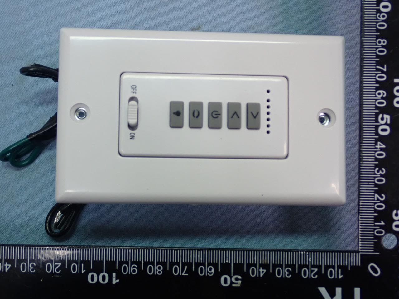
KUJCE11101
May 03, 2022Ceiling Fan Remote Controller(Transmitter)
Equipment Class
DXX - Part 15 Low Power Communication Device Transmitter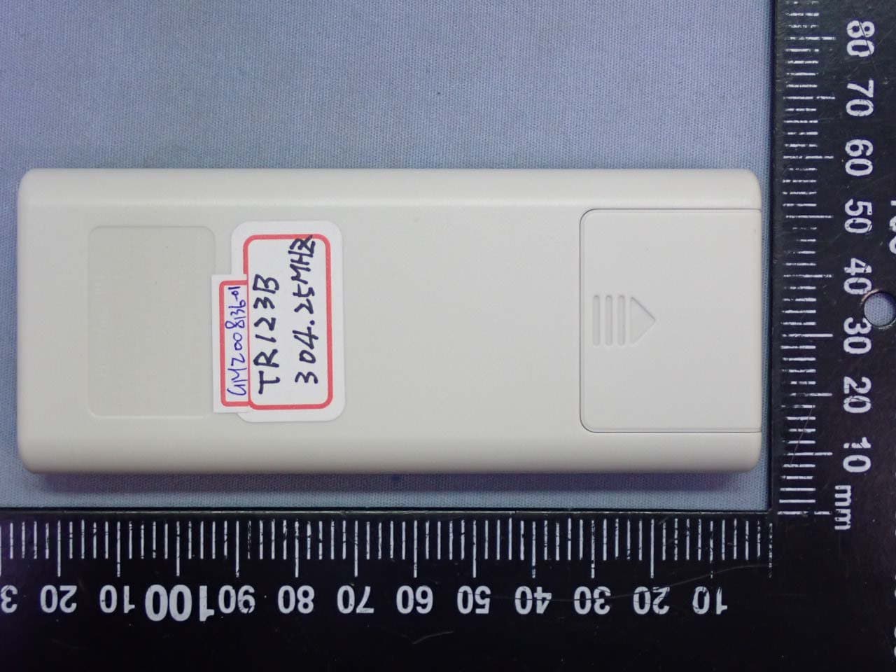
KUJCE10901
Sep 03, 2020Ceiling Fan Remote Controller (Transmitter)
Equipment Class
DSC - Part 15 Security/Remote Control Transmitter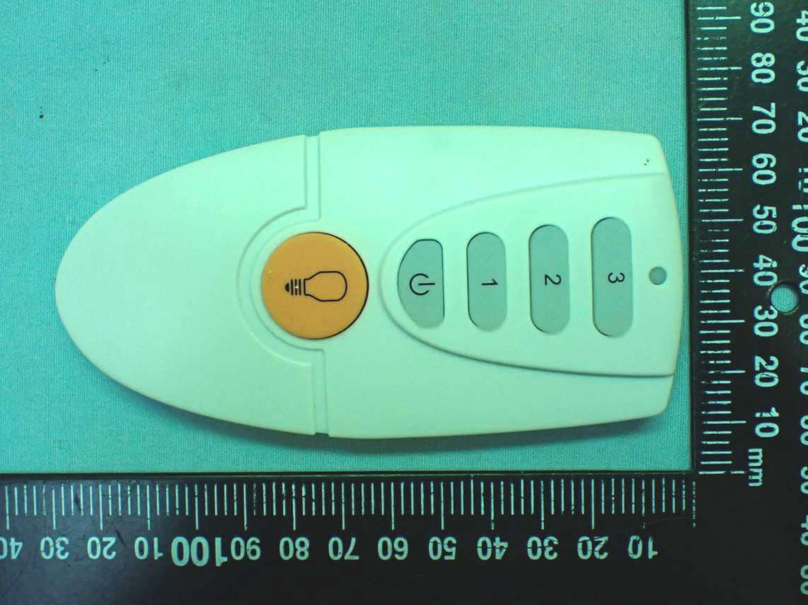
KUJCE10721
Feb 18, 2020Ceiling Fan Remote Controller (Transmitter)
Equipment Class
DSC - Part 15 Security/Remote Control Transmitter
KUJCE10406
Nov 18, 2015CEILING FAN REMOTE CONTROLLER (TRANSMITTER)
Equipment Class
DTS - Digital Transmission System
KUJCE10411
Nov 10, 2015CEILING FAN REMOTE CONTROLLER (TRANSMITTER)
Equipment Class
DSC - Part 15 Security/Remote Control Transmitter