KYPNAV01RX1RKE receiver
Yazaki North America Inc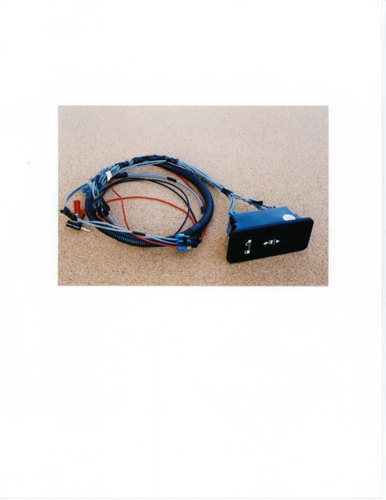
Click to zoom
Application Details
- Equipment Class
- CYY - Communications Receiver used w/Pt 15 Transmitter
- Date of Grant
- Jan 18, 2001
- Application Purpose
- Original Equipment
- Date of Application
- Dec 14, 2000
- Equipment Note
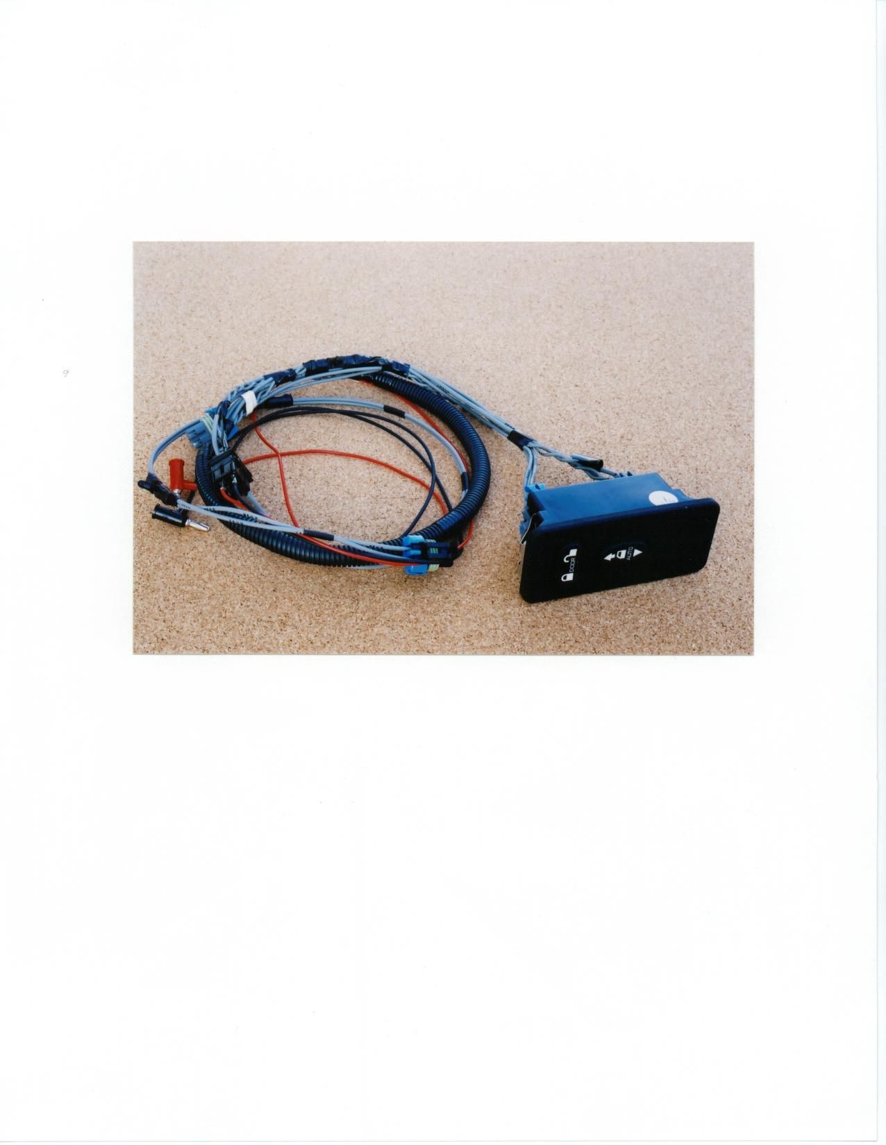
- RKE receiver
- Frequency Range
- 315.00000000 - 315.00000000
- Company
- Yazaki North America Inc
- Country
- United States
Documents & Files
Document Text
Text extracted from the exhibit documents filed with the FCC. Open a document above to read the original.
Users Manual
Re: Certification for Yazaki ‘01 NGV RKE Receiver Module Navistar PN: 35449337c2 FCC ID: KYPNAV01RX1 CANADA: XXXXXXXXXXX USER’S MANUAL The car owner’s manual is in preparation at this time. The following material will be contained in the vehicle owner’s manual. (PRELIMINARY) This device complies with Part 15 of the FCC Rules and with RSS-210 of Industry Canada. Operation is subject to the following two conditions: (1) This device may not cause harmful interference, and (2) This device must accept any interference received, including interference that may cause undesired operation. Changes or modifications not expressively approved by the party responsible for compliance could Void the user’s authority to operate the equipment.
Attestation Statements
Re: Certification for Yazaki ‘01 NGV RKE Receiver Navistar P/N: 35449337c2 FCC ID: KYPNAV01RX1 CANADA: to be provided by IC POWER OF ATTORNEY A letter granting Valdis V. Liepa the Power of Attorney is on file and can be provided when so requested. Re: Certification for Yazaki ‘01 NGV RKE Receiver Navistar P/N: 35449337c2 FCC ID: KYPNAV01RX1 CANADA: to be provided by IC REQUEST FOR CONFIDENTIALITY Pursuant to 47 CRF 0.459, Yazaki requests that a part of the subject application be held confidential. This comprises Exhibits (5) Schematics (10) Parts List (Part of Exhibit only) Yazaki has spent substantial effort in developing this product and it is one of the first of its kind in industry. Having the subject information easily available to "competition" would negate the advantage they have achieved by developing this product. Not protecting the details of the design will definitely result in a financial hardship. If there are any questions regarding this request, please contact me at the above address or call 734-647- 1792, (lab) 734-483-4211, fax 734-647-2106 or e-mail [email protected]. Sincerely, Valdis V. Liepa Research Scientist University of Michigan Re: Certification for Yazaki ‘01 NGV RKE Receiver Navistar P/N: 35449337c2 FCC ID: KYPNAV01RX1 CANADA: to be provided by IC GENERAL PRODUCT INFORMATION The device, for which certification is pursued, has been designed by: Yazaki North America, Inc. EIS Department 6801 Haggerty Rd. Canton, Michigan Fawaz Baltaji Tel: 734-983-1000 Fax: 734-983-2475 It will be manufactured by: Nacom Corporation 1495 Kalamazoo Drive Griffin, Georgia 30233 Tel: 770-412-1001 Fax: 770-412-0111 It will be marketed and serviced by: Yazaki North America, Inc. EIS Department 6801 Haggerty Rd. Canton, Michigan
Operational Description
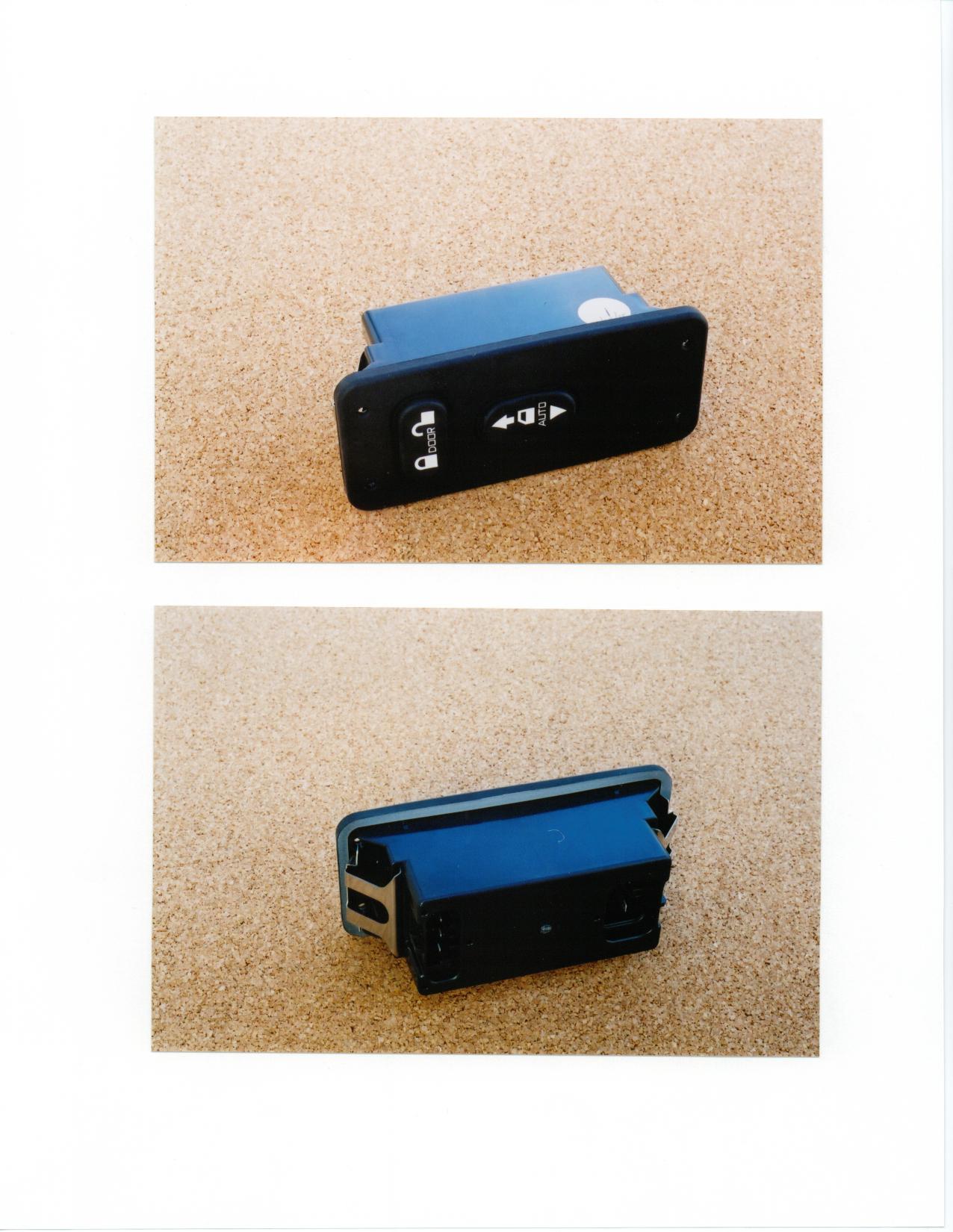
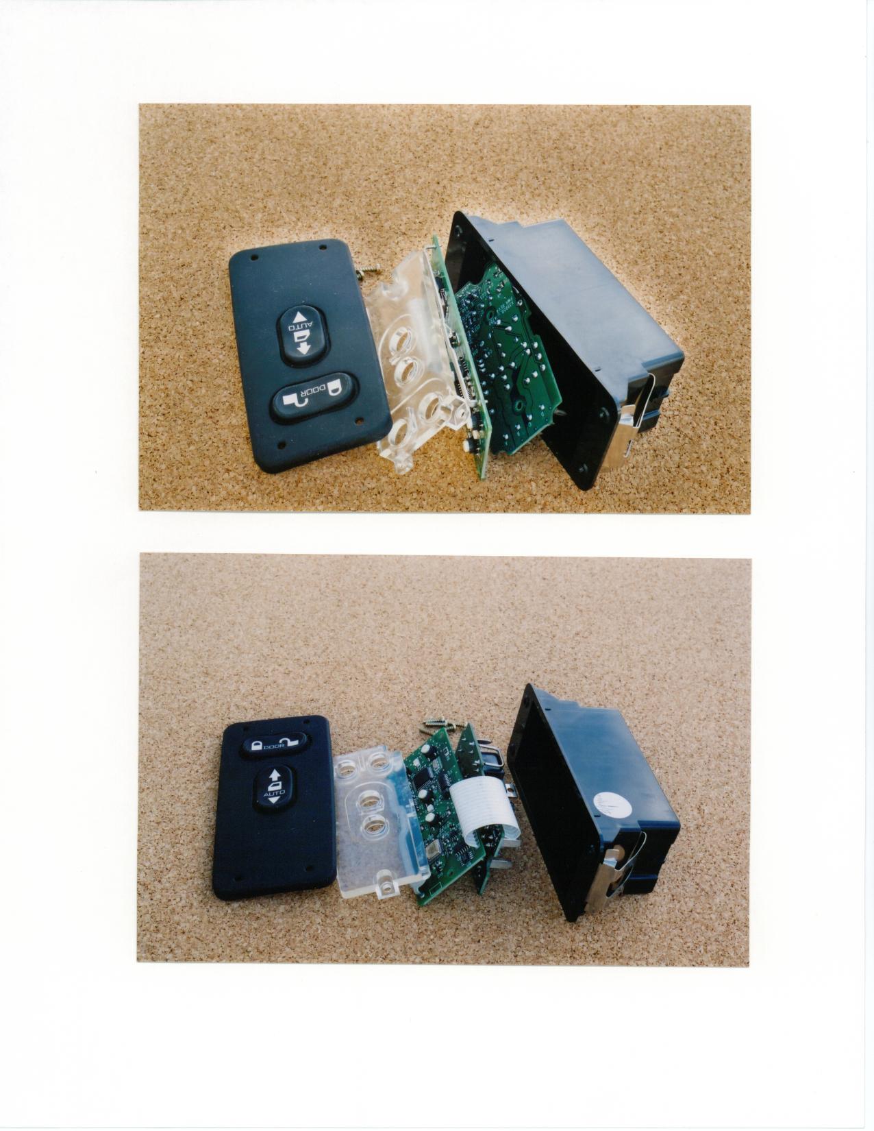
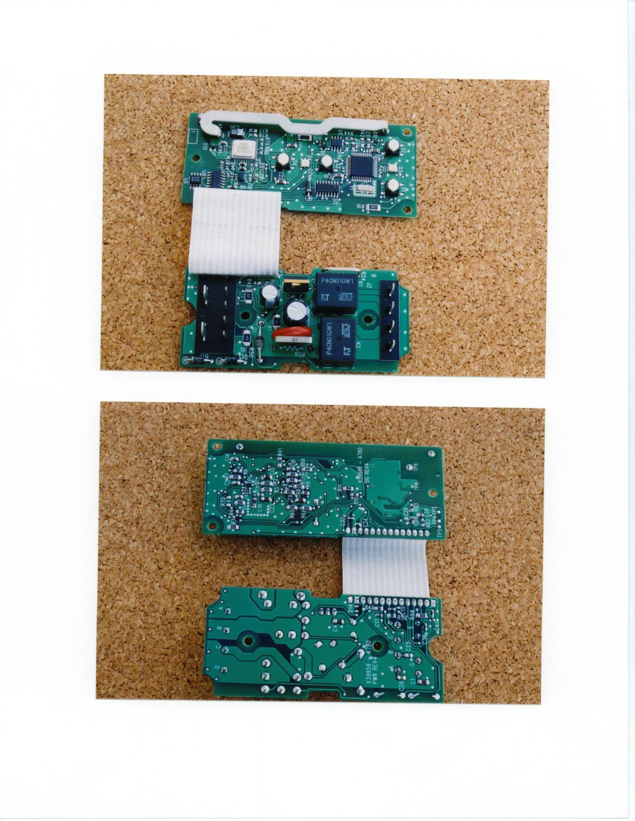
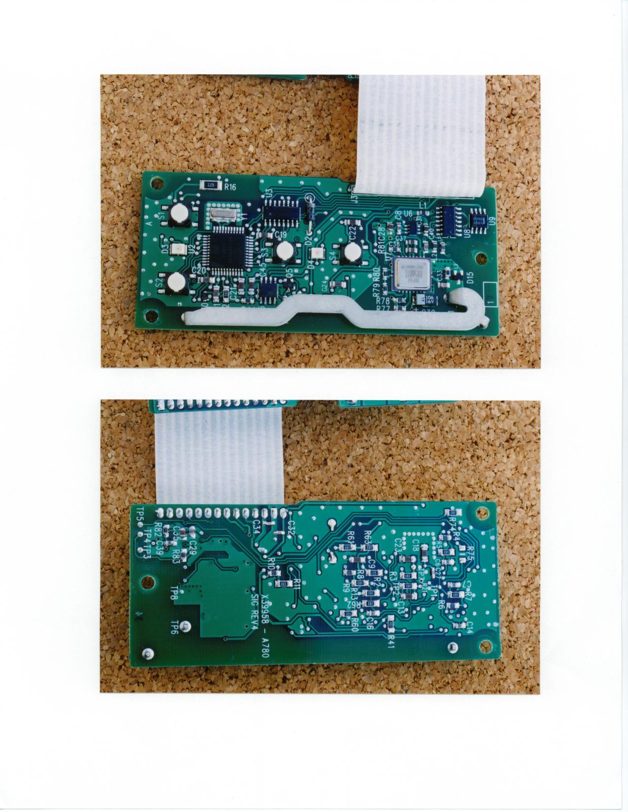
System Description 2001 Navistar RKE Receiver Module Yazaki North America P/N: 3817900-270, Navistar P/N: 35449337c2 The RKE Receiver Module consists of the housing and the main module, which consists of receiver, decoder, and a microcontroller. The internal antenna and receiver receives the low-level RF signal and sends data to the decoder. The decoder decodes the signal and sends it to the microcontroller. The microcontroller sends the J1708 message on the bus to activate the Lock, Unlock, Panic, or Auxiliary functions.
Test Report
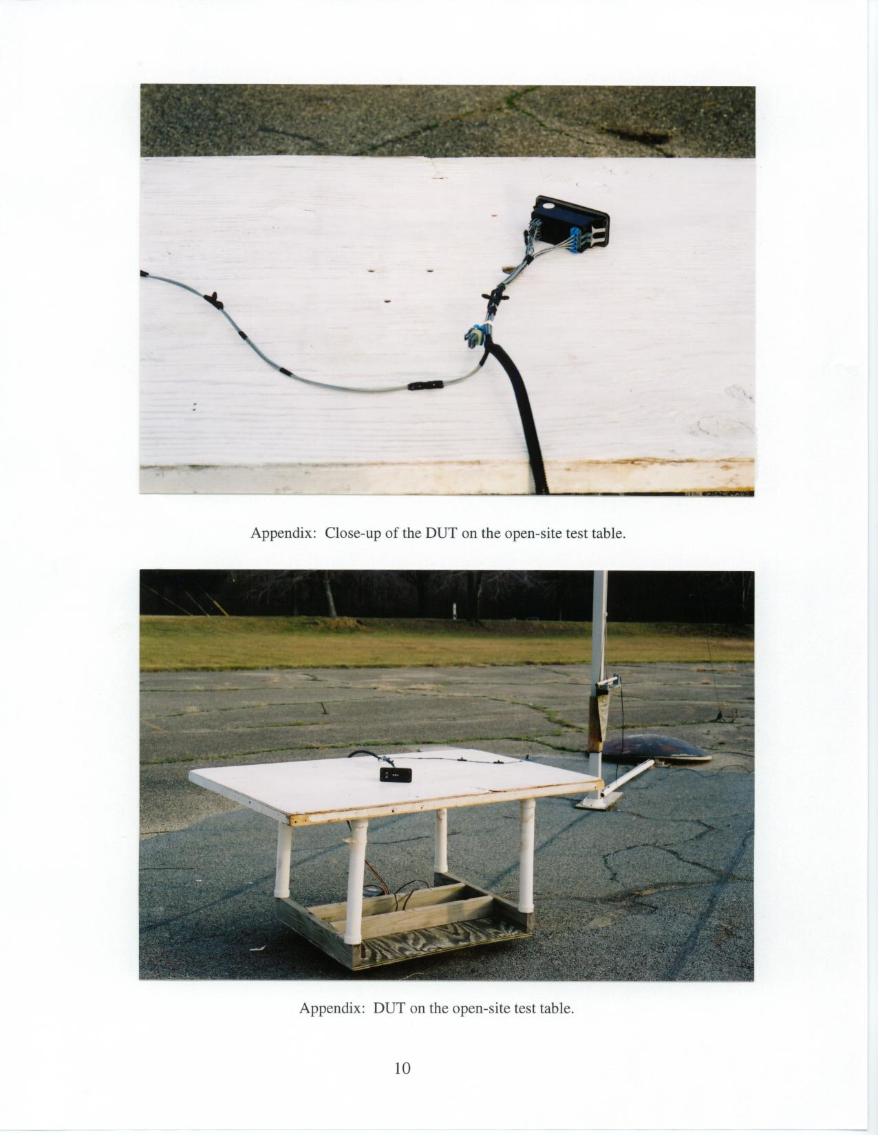
2 1. Introduction Yazaki / Navistar RKE Receiver, was tested for compliance with FCC Regulations, Part 15, adopted under Docket 87-389, April 18, 1989, and with Industry Canada RSS-210, Issue 2, dated February 14, 1998. The tests were performed at the University of Michigan Radiation Laboratory Willow Run Test Range following the procedures described in ANSI C63.4-1992 "Methods of Measurement of Radio- Noise Emissions from Low-Voltage Electrical and Electronic Equipment in the Range of 9 kHz to 40 GHz". The Site description and attenuation characteristics of the Open Site facility are on file with FCC Laboratory, Columbia, Maryland (FCC file 31040/SIT) and with Industry Canada, Ottawa, ON (File Ref. No: IC 2057). 2. Test Procedure and Equipment Used The test equipment commonly used in our facility is listed in Table 2.1 below. The second column identifies the specific equipment used in these tests. The HP 8593E spectrum analyzer is used for primary amplitude and frequency reference. Table 2.1. Test Equipment. Test Instrument Equipment Used Manufacturer/Model Cal. Date/By Spectrum Analyzer X Hewlett-Packard 8593A December 2001/U of M Rad Lab (9kHz-22GHz) SN: 3107A01358 Spectrum Analyzer X Hewlett-Packard 8593E December 2001/HP (9kHz-26GHz) SN: 3107A01131 Spectrum Analyzer Hewlett-Packard 182T/8558B November 2000/U of M Rad Lab (0.1-1500 MHz) SN: 1529A01114/543592 Preamplifier X Watkins-Johnson Oct. 2000/U of M Rad Lab (5-1000MHz) A11 -1 plus A25-1S Preamplifier X Avantek Nov. 2000/ U of M Rad Lab (5-4000 MHz) Broadband Bicone X University of Michigan June 1996/U of M Rad Lab (20-200 MHz) Broadband Bicone X University of Michigan June 1996/U of M Rad Lab (200-1000 MHz) Dipole Antenna Set X University of Michigan June 1997/U of M Rad Lab (25-1000 MHz) Dipole Antenna Set EMCO 3121C June 1996/U of M Rad Lab (30-1000 MHz) SN: 992 Active Loop Antenna EMCO 6502 December 1993/ EMCO (0.090-30MHz) SN: 2855 Active Rod EMCO 3301B December 1993/EMCO (30Hz-50 MHz) SN: 3223 Ridge-horn Antenna X University of Michigan March 1999/U of M Rad Lab (0.5-5 GHz) LISN Box X University of Michigan Dec 1997/U of M Rad Lab Signal Cables X Assorted January 1993/U of M Rad Lab X-Y Plotter Hewlett-Packard 7046A During Use/U of M Rad Lab Signal Generator X Hewlett-Packard 8656A January 1990/U of M Rad Lab (0.1-990 MHz) Printer X Hewlett-Packard 2225A August 1989/HP 3 3. Configuration and Identification of Device Under Test The DUT is a 315.0 MHz direct conversion (“ASH”) receiver, designed for onboard automobile security/convenience applications, and as such, it is powered from an automotive 12 VDC source. It is housed in a plastic case approximately 3.0 by 6.0 by 4.0 inches. Antenna is internal. For testing for radiated emissions, a 3 meter long section of generic harness was used, with power wires separated from the control/signal lines. In the receiver decoding and signal processing are performed on chip. The DUT was designed and manufactured by Yazaki North America, Inc., EIS Department, 6801 Haggerty Rd., Canton, Michigan. It is identified as: Yazaki ‘01 NGV RKE Receiver Yazaki P/N: 3817900-270 Navistar P/N: 35449337c2 FCC ID: KYPNAV01RX1 CANADA: to be determined by IC 3.1 Modifications Made There were no modifications made to the DUT by this laboratory. 4. Emission Limits For FCC the DUT falls under Part 15, Subpart B, "Unintentional Radiators". For Industry Canada the DUT falls under Receiver category and is subject to technical requirement of sections 7.1 to 7.4 in RSS- 210. The pertinent test frequencies, with corresponding emission limits, are given in Tables 4.1 and 4.2 below. 4.1 Radiated Emission Limits Table 4.1. Radiated Emission Limits (FCC: 15.33, 15.35, 15.109; IC: RSS-210, 7.3). Freq. (MHz) E lim (3m) μV/m E lim dB(μV/m) 30-88 100 40.0 88-216 150 43.5 216-960 200 46.0 960-2000 500 54.0 Note: Quasi-Peak readings apply to 1000 MHz (120 kHz BW) Average readings apply above 1000 MHz (1 MHz BW) 4.2 Conducted Emission Limits Table 4.2. Conducted Emission Limits (FCC: 15.107; IC: RSS-210, 6.6). Freq. (MHz) μV dB(μV) 0.450 - 1.705 250 48.0 1.705 - 30.0 250 48.0 Note: Quasi-Peak readings apply here 4 5. Emission Tests and Results 5.1 Anechoic Chamber Radiated Emission Tests To familiarize with the radiated emission behavior of the DUT, it was studied and measured in the shielded anechoic chamber. In the chamber there is a set-up similar to that of an outdoor 3-meter site, with turntable, antenna mast, and a ground plane. Instrumentation includes spectrum analyzers and other equipment as needed. To study and test for radiated emissions, the DUT was powered by a laboratory power supply at 12.0 VDC. A 315 MHz CW signal was injected (radiated) from a nearby signal generator using a short wire antenna. The DUT was placed on the test table on each of its three axis. For each placement, the table was rotated to obtain maximum signal for vertical and horizontal emission polarizations. This sequence was repeated throughout the required frequency range. In the chamber we studied and recorded all the emissions using a ridge-horn antenna, which covers 200 MHz to 5000 MHz, up to 2 GHz. In scanning from 30 MHz to 2.0 GHz, there were no spurious emissions observed other than the LO, the injection signal, and the LO harmonics. Figures 5.1 and 5.2 show emissions measured 0-1000 MHz and 1000-2000 MHz, respectively. These measurements are made with a ridge-horn antenna at 3m, with spectrum analyzer in peak hold mode and the receiver rotated in all orientations. The measurements up to 1000 MHz (Fig. 5.1) are used for initial evaluation only, but those above 1000 MHz (Fig. 5.2) are used in final assessment for compliance. 5.2 Open Site Radiated Emission Tests The DUT was then moved to the 3 meter Open Field Test Site where measurements were repeated up to 1000 MHz using a small bicone, or dipoles when the measurement is near the limit. The DUT was exercised as described in Sec. 5.1 above. The measurements were made with a spectru…
Text truncated - open the document above for the full version.
Contact Information
Applicant
Kevin Pimlott(Chief Engineer)
Technical Contact
University of Michigan/EECSValdis V Liepa
[email protected]734-483-4211
1301 Beal Avenue · Ann Arbor, Michigan · United States
Non-Technical Contact
University of Michigan/EECSValdis V Liepa
[email protected]734-483-4211
Test Firm
University of MichiganValdis Liepa
Technical Specifications
| # | Rule Parts | Frequency Range | Power Output |
|---|---|---|---|
| 1 | 15B | 315 MHz - 315 MHz | - |
Other Applications from Yazaki North America Inc
KYPNAV01TX1
Jun 19, 2000Remote Keyless Entry/Security Device
Equipment Class
DSC - Part 15 Security/Remote Control TransmitterKYPTO4C98JX
Jan 15, 1998Auto Security System Transmitter
Equipment Class
DSC - Part 15 Security/Remote Control TransmitterKYPT03C98JA
Jun 12, 1997Car Alarm System Transmitter
Equipment Class
DSC - Part 15 Security/Remote Control TransmitterKYPR02F98MN
Apr 16, 1997Automobile Security Receiver
Equipment Class
CRR - Superregenerative ReceiverKYPTX002
Jun 12, 1996Automobile Security Transmitter
Equipment Class
DSC - Part 15 Security/Remote Control Transmitter