KYPNAV01TX1Remote Keyless Entry/Security Device
Yazaki North America Inc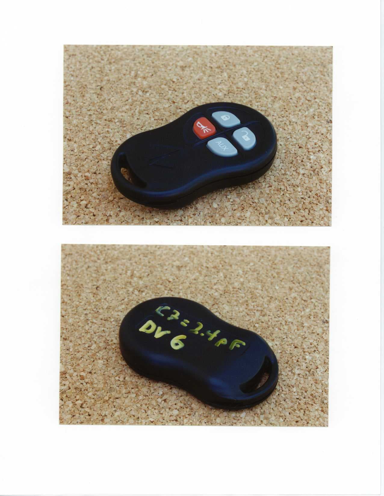
Click to zoom
Application Details
- Equipment Class
- DSC - Part 15 Security/Remote Control Transmitter
- Date of Grant
- Jun 19, 2000
- Application Purpose
- Original Equipment
- Date of Application
- Jun 07, 2000
- Equipment Note
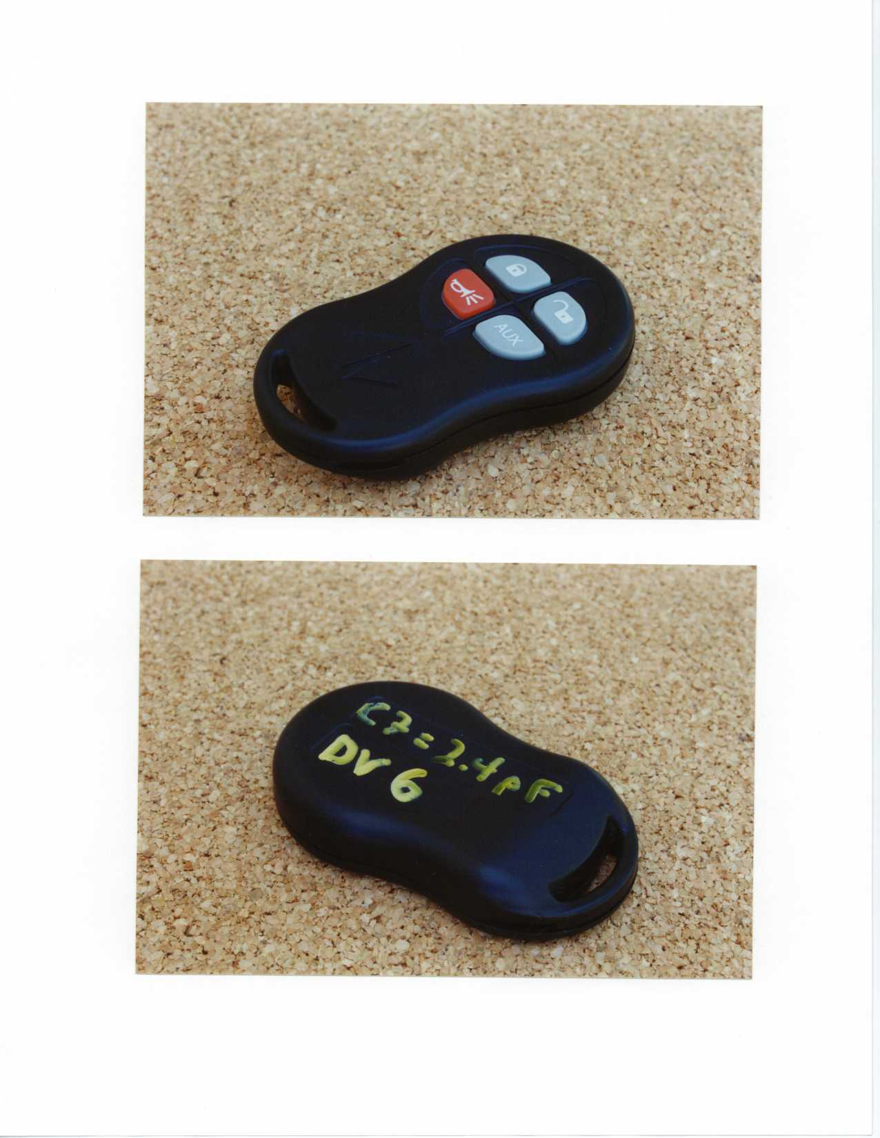
- Remote Keyless Entry/Security Device
- Frequency Range
- 315.00000000 - 315.00000000
- Company
- Yazaki North America Inc
- Country
- United States
Documents & Files
Document Text
Text extracted from the exhibit documents filed with the FCC. Open a document above to read the original.
Users Manual
Re: Certification for Yazaki 2001 NGV RKE Transmitter PN:3544938c2 FCC ID: KYPNAV01TX1 CANADA: USER’S MANUAL The car owner’s manual is in preparation at this time. The following material will be contained in the vehicle owner’s manual. (PRELIMINARY) This device complies with Part 15 of the FCC Rules and with RSS-210 of Industry Canada. Operation is subject to the following two conditions: (1) This device may not cause harmful interference, and (2) This device must accept any interference received, including interference that may cause undesired operation. Changes or modifications not expressively approved by the party responsible for compliance could Void the user’s authority to operated the equipment.
Attestation Statements
Yazaki North America, Inc. May 24, 2000 Navistar RKE Transmitter Yazaki P/N: 3817900-280 Navistar P/N: 3544938c2 FCC ID: KYPNAV01TX1 CANADA:------------------ The Navistar RKE transmitter (Yazaki P/N: 3817900-280), for which a certification is pursued operates at 315 MHz +/- 250 kHz and has been designed by: Yazaki North America, Inc . EIS Department 6801 Haggerty Rd. Canton, Michigan Phone: (734) 983-1000 Fax: (734)983-2475 - Fawaz Baltaji , Principal Engineer, Wireless Technology - Kevin Pimlott , Executive Chief Engineer, EIS The Navistar RKE transmitter (Yazaki P/N: 3817900-280) will be manufactured at the following location: Nacom Corporation 1495 Kalamazoo Drive Griffin, Georgia 30233 Phone: (770) 412-1001 Fax: (770) 412-0111 - Sam Nwogwugwu, Manager, Production Control - Gina Tardy, Quality Control
Operational Description
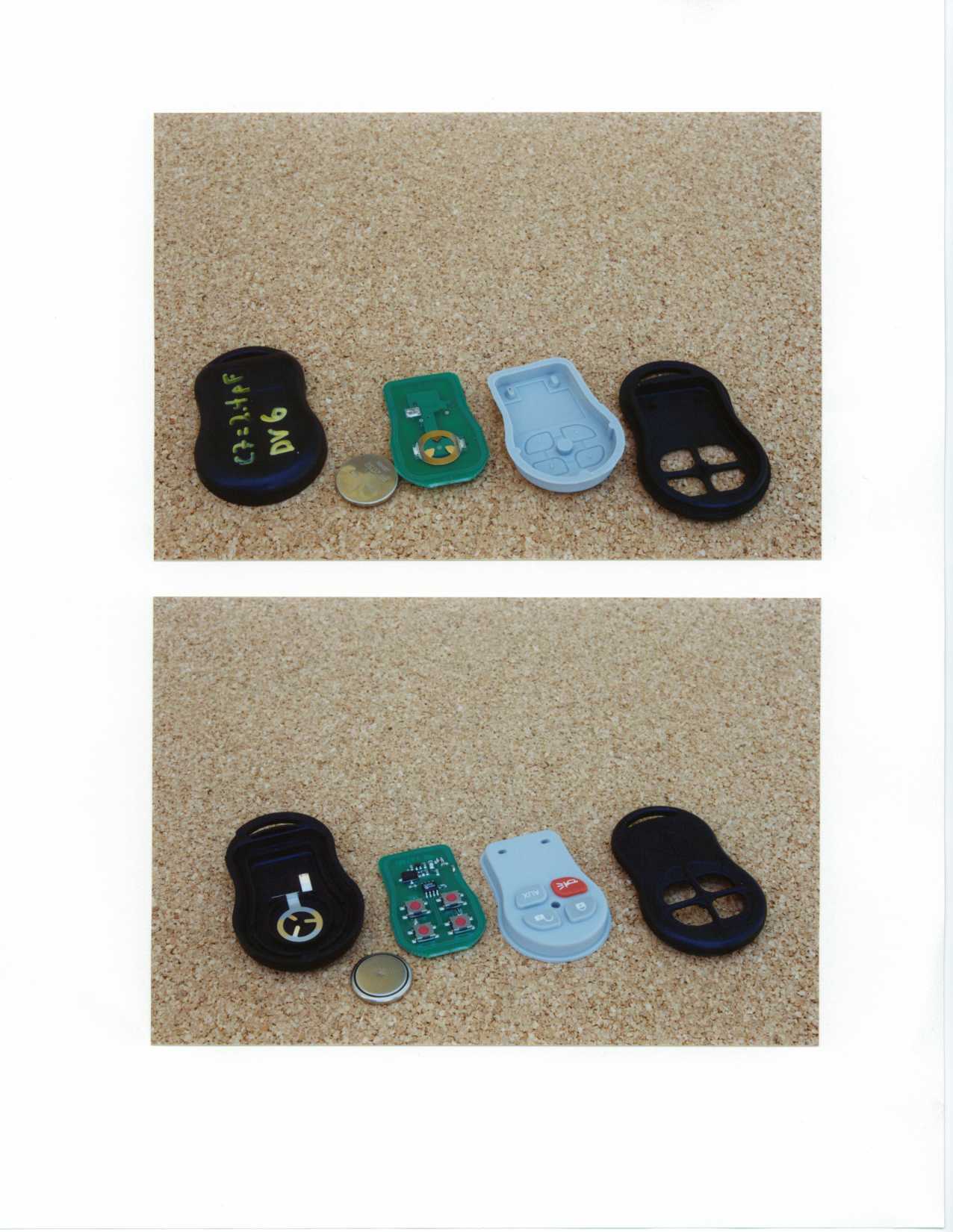
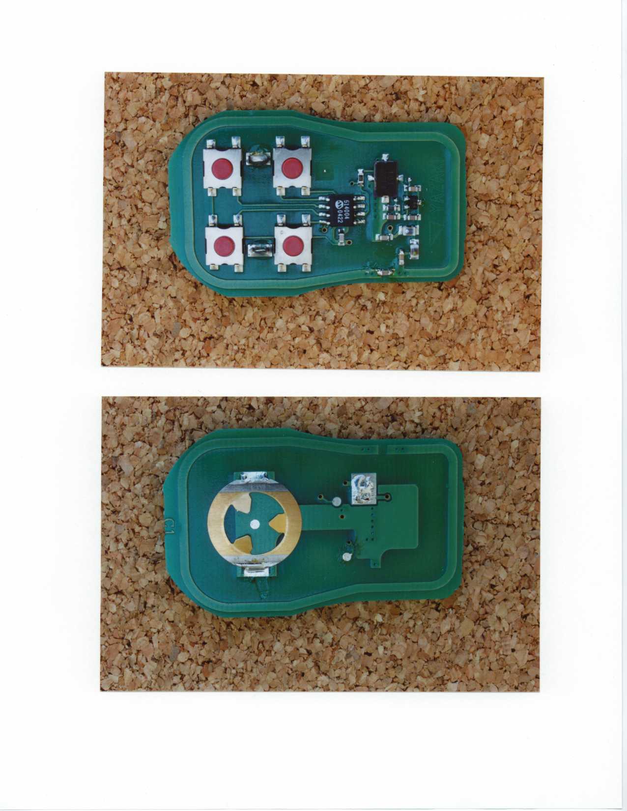
System Description of Operation 2001 Navistar RKE Transmitter Yazaki North America P/N: 3817900-280, Navistar P/N: 3544938c2 The RKE transmitter consists of the housing, four control buttons, a microcontroller, a 315 MHz SAW stabilized oscillator, and one 3-volt lithium battery. The microcontroller generates a rolling code that switches the RF oscillator ON/OFF. The integrated PCB trace antenna then radiates the RF signal. Once a button (Lock, Unlock, Panic, and Aux.) is activated, the microcontroller impresses the coded data onto the RF oscillator. The RF carrier is then turned off by the microcontroller after a preset time even if the button is held down.
Parts List/Tune Up Info
Parts List ITEM QUAN. REF. DES. DESCRIPTION VALUE 1 1 U1 Encoder, IC HCS300 2 1 Q1 RF Transistor NE94430 3 1 Y1 SAW RO2073A 4 2 C1, C2 Capacitor 470pF 5 1 C3 Capacitor 1.0pF 6 1 C4 Capacitor 7.0pF 7 1 C5 Capacitor 10.0pF 8 1 C6 Capacitor 3.3pF 9 1 C7 Capacitor 2.4pF 10 1 L1 Inductor 39nH 11 1 L2 Inductor 100nH 12 1 R1 Resistor 22K 13 1 R2 Resistor 100 ohms 14 1 B1 Battery - 3 volt CR2032 15 4 S1, S2, S3, S4 Switches 16 1 Transmitter Board 17 1 Upper Case 18 1 RKE Seal/Button 19 1 Lower Case 20 1 Upper Battery Terminal 21 1 Lower Battery Terminal 22 1 Key Ring TOTAL: 26
Contact Information
Applicant
Kevin Pimlott(Chief Engineer)
Technical Contact
University of Michigan/EECSValdis V Liepa
[email protected]734-483-4211
1301 Beal AVE. · Ann Arbor, Michigan · United States
Non-Technical Contact
University of Michigan/EECSValdis V Liepa
[email protected]734-483-4211
Test Firm
University of MichiganValdis Liepa
Technical Specifications
| # | Rule Parts | Frequency Range | Power Output |
|---|---|---|---|
| 1 | 15C | 315 MHz - 315 MHz | - |
Other Applications from Yazaki North America Inc
KYPNAV01RX1
Jan 18, 2001RKE receiver
Equipment Class
CYY - Communications Receiver used w/Pt 15 TransmitterKYPTO4C98JX
Jan 15, 1998Auto Security System Transmitter
Equipment Class
DSC - Part 15 Security/Remote Control TransmitterKYPT03C98JA
Jun 12, 1997Car Alarm System Transmitter
Equipment Class
DSC - Part 15 Security/Remote Control TransmitterKYPR02F98MN
Apr 16, 1997Automobile Security Receiver
Equipment Class
CRR - Superregenerative ReceiverKYPTX002
Jun 12, 1996Automobile Security Transmitter
Equipment Class
DSC - Part 15 Security/Remote Control Transmitter