L3M871VHFRE429NT + VHF 4M/2M Paging Receivers
Swissphone Wireless AG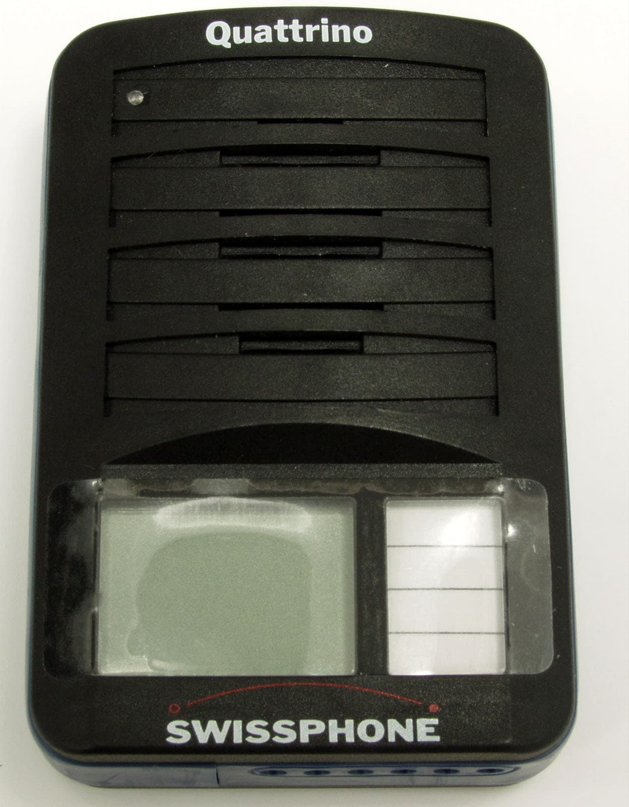
Click to zoom
Application Details
- Equipment Class
- CXX - Communications Rcvr for use w/ licensed Tx and CBs
- Date of Grant
- Aug 25, 2003
- Application Purpose
- Original Equipment
- Date of Application
- Aug 25, 2003
- Equipment Note
- RE429NT + VHF 4M/2M Paging Receivers
- Frequency Range
- 146.00000000 - 174.00000000
- Company
- Swissphone Wireless AG
- Country
- Switzerland
Documents & Files
Document Text
Text extracted from the exhibit documents filed with the FCC. Open a document above to read the original.
Users Manual
copy rights byOperating Manual RE429NT+ / Opmanual429NT+.docpage 1/9 Swissphone Telecom Roosstrasse 53 CH-8832 WollerauPMA/D000120edition 1 / 3. February 2003 Operating Manual RE429NT+ Quattrino tone, eco, voice, memo We congratulate you on your new Pager from the RE429 family. You now have a device which dominates with its performance, equipment and operational safety. Despite the simple handling of the unit, we would recommend that you read through the operating manual thoroughly. We are sure that you will find a true and reliable companion in your Pager. Contents 1Introduction...................................................................................................3 2Putting into operation....................................................................................3 2.1 Power supply ..........................................................................................3 2.2 Inserting the battery ................................................................................3 2.3 Automatic switch-on ...............................................................................3 2.4 Switching off ...........................................................................................4 2.5 Switching on ...........................................................................................4 2.6 Selecting the operating status ................................................................4 3The complete LCD Displays .........................................................................5 3.1 Quattrino voice, memo ...........................................................................5 3.2 Quattrino tone,eco ..................................................................................5 3.3 Acoustic ON............................................................................................6 3.4 Mini-beep................................................................................................6 3.5 Acoustic OFF..........................................................................................6 3.6 Monitor ..........................................................................................6 3.7 Volume ...................................................................................................6 3.8 Field strength alarm ................................................................................6 3.9 Address display ......................................................................................7 3.10 Switching ON and OFF of the activated addresses ..............................7 3.11 Message ...............................................................................................7 3.12 Battery status indicator .........................................................................7 3.13 Battery / accumulator recognition.........................................................7 3.14 New message .......................................................................................8 3.15 Call retrieving........................................................................................8 3.16 Call signalling.......................................................................................8 3.17 Alarm timer ...........................................................................................8 3.18 Acknowledgement / deletion .................................................................9 4General.........................................................................................................9 4.1 Battery operational life ............................................................................9 4.2 Week battery ..........................................................................................9 4.3 Illumination .............................................................................................9 4.4 Accessories ............................................................................................9 4.5 Customer service....................................................................................9 copy rights byOperating Manual RE429NT+ / Opmanual429NT+.docpage 2/9 Swissphone Telecom Roosstrasse 53 CH-8832 WollerauPMA/D000120edition 1 / 3. February 2003 WARNING • Do not operate this product in hazardous atmosphere or explosion risk areas. • Do not open device or remove labels * This device complies with Part 15 of the FCC Rules. Operation is subject to the following two conditions: (1) This device may not cause harmful interference, and (2) This device must accept any interference received, including interference that may cause undesired operation. Made in Switzerland WARNING Changes or modifications not expressly approved by the party responsible for compliance could void the user's authority to operate the equipment. copy rights byOperating Manual RE429NT+ / Opmanual429NT+.docpage 3/9 Swissphone Telecom Roosstrasse 53 CH-8832 WollerauPMA/D000120edition 1 / 3. February 2003 1 Introduction The unit has a large number of operational functions. The delivered unit contains a selection of these as a basic setting. These operating functions are shown in the display, and can be activated by the user. If this selection does not meet your requirements, additional functions can be programmed as required with the Programmig device. You can find information about the type and scope of functions that can be programmed in the operating manual, or you can contact your supplier or SWISPHONE directly. 2 Putting into operation 2.1 Power supply This family of units is preferably operated using an environmentally-friendly, re- chargeable power source (batteries). These batteries are available in the AA (Mignon) size as nickel-cadmium 600 mAh (Sanyo) or NiMH (nickel metal hydride) 1400 mAh (Varta, Furukuwa), and can be re-charged by various types of re-charging unit. As an alternative, the unit can be fed from dry batteries. In this case, only high- quality dry batteries intended…
Text truncated - open the document above for the full version.
Operational Description
Technical Description RE 429NT+ VHF 2m / 4m The basic functions of the main stages of the RE 429 are described below. The main board together with the sub-board constitute a functional unit. The complete board assembly is combined on a printed circuit board assembly jig and passes along the complete assembly process through to the adjustment and check of the data content. The pair of printed circuit boards are tuned together by means of the common learning process and can be treated as a self-contained functional unit. Contents: Technical Description RE 429NT+ VHF 2m / 4m.............................................1 1 MAIN BOARD RE429NT+............................................................................2 1.1 Power source and DC supply.................................................................2 1.2 Antenna / Amplifier / Filter......................................................................2 1.3 Crystall oscillator ....................................................................................3 1.4 First mixer / Filter ....................................................................................3 1.5 μP Microprocessor / μP-Clock / Reference voltage................................3 1.6 EEPROM................................................................................................4 1.7 Correlator................................................................................................4 1.8 AF-Amplifier............................................................................................4 1.9 Visual and audio indicators.....................................................................4 1.10 LCD Liquid Cristal Display....................................................................5 1.11 Vibrator.................................................................................................6 1.12 Key functions........................................................................................6 2 SUBPRINT RE429NT+................................................................................6 2.1 DC-Voltage.............................................................................................7 2.2 DC/DC-Converter...................................................................................7 2.3 ZF- IC.....................................................................................................7 2.4 Squelch...................................................................................................8 2.5 Speech memory.....................................................................................8 3 PRINT INTERFACES OF RE429NT+..........................................................9 3.1 Connection from Main board - Subprint..................................................9 4 CONNECTION FROM RECEIVER TO PERIPHERAL UNIT ........................10 copy rights by Description RE429NT+ / QTNT+BS2M2E page 1/10 Swissphone Telecom Roosstrasse 53 CH-8832 Wollerau PMA/D000 120 edition 1 / 13.08.03 1 MAIN BOARD RE429NT+ The main board is designed as a 4 layer printed circuit board and is mounted with SMD components. The functional units and stages described below are contained on this board. One important functional group comprises the HF input stage, oscillator and mixer up to the first IF signal processor. Another functional group combines the μP with clock generator, EEPROM, correlator, reference voltage and the push-button boards. The AF output amplifier with loudspeaker, indicator LEDs, vibrator and LCD are mounted on the reverse side of the main boad. 1.1 Power source and DC supply The accumulator (nom. voltage= 1.26 V) or a battery serve as the power source. The main board requires the following supply voltages: V BAT = 1.26V /DC for the AF amplifier, vibrator, lamps, voltage monitor and supply of various transistor stages V DD = 3 V/DC for the μP, correlator and EEPROM V+= 1V/regulated for the HF-transistors. Both the supply voltages V DD =3 V and V+=1V are generated in the receiver using the DC/DC converter and the IF-IC (both on the sub-board). If the accumulator voltage falls below 1.2V the battery alarm is activated via the μP (periodic beeping). From this moment on, the equipment is able to function for approximately five more hours. If the voltage drops below 1V DC for a short period, the equipment switches to the startup condition. NiCd accumulators should be preferably used for the power source. It should be noted that when using a battery, the receiver recognizes it as a battery and therefore it cannot be charged. 1.2 Antenna / Amplifier / Filter The signal is picked up via the ferrite antenna L1. The antenna is tuned to resonance using capacitors C1,C2,C3 and C4. The signal is then amplified by transistor T1 which operates in the common base mode. The desired frequency band is selected using a coupled filter comprising the two shunt resonant circuits L11/C11/C12 and L13/C13/C14. copy rights by Description RE429NT+ / QTNT+BS2M2E page 2/10 Swissphone Telecom Roosstrasse 53 CH-8832 Wollerau PMA/D000 120 edition 1 / 13.08.03 1.3 Crystall oscillator The oscillator uses the Colpitts configuration. The coupled bandpass filter with the two inductors L22 and L23 is necessary for selection of the oscillator signal. The crystal frequency is doubled in the collector circuit for operation in the 2 m band. The oscillator output is coupled to the mixer via coupling capacitor C25. The oscillator frequency is 21.4 MHz higher than the received signal for the 4 m band as well as the lower and middle 2 m bands. For the upper 2 m band, the oscillator frequency is 21.4 MHz lower than the received signal. 1.4 First mixer / Filter The dual gate MOSFET T51 mixes the amplified input signal from the antenna with the local oscillator signal to generate the first IF signal at a frequency of 21.4 MHz. The resonant circuit formed by L51/C51 forms the load for this stage. The IF-signal is then filtered by the crystal filter F…
Text truncated - open the document above for the full version.
Parts List/Tune Up Info
Sprintel Communications AG CH 8833 Samstagern 25. Sep. 02 ID-Nr.Pos. EinbauhinweisBezeichnung Layerunabhängig STL-Nr. 0910475 RE429 Flex gebogen 5 Wdg. 02090231Antennen-Flex 34MM 80-Nutzen, Index B. Printlayer 1 STL-Nr. 0529051 PS RE429 2M-UB Basis L1 028145720RE429 Abschirmblech 028144519DV300 Abschirmrahmen 01655013 C11SMD-Trimmer 2 - 6P TZB4Z060AB10R00 01655014 C13SMD-Trimmer 2 - 6P TZB4Z060AB10R00 09999985 C14"nicht bestückt" 01655051 C2SMD-Trimmer 3 - 10P TZB4S100AB10R00 01655066 C20SMD-Trimmer 7 - 50P TZB4R500AB10R00 00670707 C23C SMD 5P6 NPO 0603 +/- 0.25P 00670118 C24C SMD 1P0 NPO 0603 +/- 0.25P 00671519 C25C SMD 22P NPO 0603 +/- 5% 016550510 C26SMD-Trimmer 3 - 10P TZB4S100AB10R00 016550511 C27SMD-Trimmer 3 - 10P TZB4S100AB10R00 00672012 C4C SMD 56P NPO 0603 +/- 5% 022506112 L1Ferritstab 10,8X6,7X32 mm 39-107-35 017326014 L11L SMD 180NH +/- 5% 017326015 L13L SMD 180NH +/- 5% 017333017 L21L SMD 680NH +/- 5% 017621016 L22L SMD 68nH +/-10% HK CHIP0805 017621016 L23L SMD 68nH +/-10% HK CHIP0805 Bearbeiter: AVORAVOR Seite 1 von 1 Sprintel Communications AG CH 8833 Samstagern 25. Sep. 02 ID-Nr.Pos. EinbauhinweisBezeichnung Layerunabhängig STL-Nr. 0910475 RE429 Flex Antenne gebogen 5 Wdg. 02090231Antennen-Flex 34MM 80-Nutzen, Index B. Printlayer 1 STL-Nr. 0529053 PS RE429 2M-MB Basis L1 028145719RE429 Abschirmblech 028144518DV300 Abschirmrahmen 01655013 C11SMD-Trimmer 2 - 6P TZB4Z060AB10R00 01655014 C13SMD-Trimmer 2 - 6P TZB4Z060AB10R00 09999985 C14"nicht bestückt" 01655051 C2SMD-Trimmer 3 - 10P TZB4S100AB10R00 01655066 C20SMD-Trimmer 7 - 50P TZB4R500AB10R00 00670617 C23C SMD 4P7 NPO 0603 +/- 0.25P 00670118 C24C SMD 1P0 NPO 0603 +/- 0.25P 00671519 C25C SMD 22P NPO 0603 +/- 5% 016550510 C26SMD-Trimmer 3 - 10P TZB4S100AB10R00 016550511 C27SMD-Trimmer 3 - 10P TZB4S100AB10R00 00672012 C4C SMD 56P NPO 0603 +/- 5% 022506112 L1Ferritstab 10,8X6,7X32 mm 39-107-35 017326014 L11L SMD 180NH +/- 5% 017325015 L13L SMD 150NH +/- 5% 017333017 L21L SMD 680NH +/- 5% 017621016 L22L SMD 68nH +/-10% HK CHIP0805 017621016 L23L SMD 68nH +/-10% HK CHIP0805 Bearbeiter: AVORAVORSeite 1 von 1 Sprintel Communications AG CH 8833 Samstagern 25. Sep. 02 ID-Nr.Pos. EinbauhinweisBezeichnung Printlayer 4 STL-Nr. 0536068 PS RE429+ 4M-MB Basis L4 00651901 C1C SMD 47P NPO 0805 +/- 5% 00671714 C10C SMD 33P NPO 0603 +/- 5% 00670816 C12C SMD 6P8 NPO 0603 +/- 0.25P 09999987 C21"nicht bestückt" 00671315 C22C SMD 15P NPO 0603 +/- 5% 00671112 C3C SMD 10P NPO 0603 +/- 5% 09999988 C30"nicht bestückt" 00670519 C31C SMD 3P9 NPO 0603 +/- 0.25P 00671903 C9C SMD 47P NPO 0603 +/- 5% 003355113 R12R SMD 33K CHIP-R 0603 +/-1% 003334111 R21R SMD 560E CHIP-R 0603 +/-1% 003334112 R22R SMD 560E CHIP-R 0603 +/-1% 003351110 R3R SMD 15K CHIP-R 0603 +/-1% Bearbeiter: AVORAVOR Seite 1 von 1 Sprintel Communications AG CH 8833 Samstagern 25. Sep. 02 ID-Nr.Pos. EinbauhinweisBezeichnung Printlayer 4 STL-Nr. 0536066 PS RE429+ 4M-UB Basis L4 00652111 C1C SMD 68P NPO 0805 +/- 5% 00671814 C10C SMD 39P NPO 0603 +/- 5% 00670906 C12C SMD 8P2 NPO 0603 +/- 0.25P 09999987 C21"nicht bestückt" 00671415 C22C SMD 18P NPO 0603 +/- 5% 00671212 C3C SMD 12P NPO 0603 +/- 5% 00670308 C30C SMD 2P2 NPO 0603 +/- 0.25P 09999989 C31"nicht bestückt" 00671903 C9C SMD 47P NPO 0603 +/- 5% 099999813 R12"nicht bestückt" 003334111 R21R SMD 560E CHIP-R 0603 +/-1% 003334112 R22R SMD 560E CHIP-R 0603 +/-1% 003351110 R3R SMD 15K CHIP-R 0603 +/-1% Bearbeiter: AVORAVOR Seite 1 von 1 Sprintel Communications AG CH 8833 Samstagern 25. Sep. 02 ID-Nr.Pos. EinbauhinweisBezeichnung Printlayer 4 STL-Nr. 0536064 PS RE429+ 2M-OB Basis L4 00650401C1C SMD 3P3 NP0 0805 +/- 0,25P 00670904C10C SMD 8P2 NPO 0603 +/- 0.25P 099999813C12"nicht bestückt" 09999987C21"nicht bestückt" 00671815C22C SMD 39P NPO 0603 +/- 5% 09999982C3"nicht bestückt" 09999988C30"nicht bestückt" 09999989C31"nicht bestückt" 00671413C9C SMD 18P NPO 0603 +/- 5% 00334916R12R SMD 10K CHIP-R 0603 +/-1% 003334111R21R SMD 560E CHIP-R 0603 +/-1% 003334112R22R SMD 560E CHIP-R 0603 +/-1% 003351110R3R SMD 15K CHIP-R 0603 +/-1% Bearbeiter: AVORAVORSeite 1 von 1 Sprintel Communications AG CH 8833 Samstagern 25. Sep. 02 ID-Nr.Pos. EinbauhinweisBezeichnung Printlayer 4 STL-Nr. 0536062 PS RE429+ 2M-MB Basis L4 00650611 C1C SMD 4P7 NP0 0805 +/- 0,25P 00670904 C10C SMD 8P2 NPO 0603 +/- 0.25P 099999813 C12"nicht bestückt" 09999987 C21"nicht bestückt" 00671515 C22C SMD 22P NPO 0603 +/- 5% 09999982 C3"nicht bestückt" 09999988 C30"nicht bestückt" 09999989 C31"nicht bestückt" 00671413 C9C SMD 18P NPO 0603 +/- 5% 00334916 R12R SMD 10K CHIP-R 0603 +/-1% 003334111 R21R SMD 560E CHIP-R 0603 +/-1% 003334112 R22R SMD 560E CHIP-R 0603 +/-1% 003351110 R3R SMD 15K CHIP-R 0603 +/-1% Bearbeiter: AVORAVOR Seite 1 von 1 Sprintel Communications AG CH 8833 Samstagern 25. Sep. 02 ID-Nr.Pos. EinbauhinweisBezeichnung Printlayer 4 STL-Nr. 0536060 PS RE429+ 2M-UB Basis L4 00650701 C1C SMD 5P6 NP0 0805 +/- 0,25P 00670904 C10C SMD 8P2 NPO 0603 +/- 0.25P 099999813 C12"nicht bestückt" 09999987 C21"nicht bestückt" 00671515 C22C SMD 22P NPO 0603 +/- 5% 09999982 C3"nicht bestückt" 09999988 C30"nicht bestückt" 09999989 C31"nicht bestückt" 00671413 C9C SMD 18P NPO 0603 +/- 5% 00334916 R12R SMD 10K CHIP-R 0603 +/-1% 003334111 R21R SMD 560E CHIP-R 0603 +/-1% 003334112 R22R SMD 560E CHIP-R 0603 +/-1% 003351110 R3R SMD 15K CHIP-R 0603 +/-1% Bearbeiter: AVORAVORSeite 1 von 1 Sprintel Communications AG CH 8833 Samstagern 25. Sep. 02 ID-Nr.Pos. EinbauhinweisBezeichnung Printlayer 1 STL-Nr. 0536045 PS RE429NT+ mit MEMO SUB L1 028145813RE429 Abschirmung 01081923 C160C SMD 10U/4V Tantal 3.2x1.6 00675401 C161C SMD 100N X7R 0603 +/-10% 00675401 C162C SMD 100N X7R 0603 +/-10% 00675401 C163C SMD 100N X7R 0603 +/-10% 09999982 C164"nicht bestückt" 09999982 C165"nicht bestückt" 09999982 C166"nicht bestückt" 00676604 C167C SMD 1UF Y5V 0603+80/-20% 10V 00675401 C168C SMD 100N X7R 0603 +/-10% 00675401 C169C SMD 100N X7R 0603 +/-10% 01081923 C170C SMD 10U/4V Tantal 3.2x1.6 00676604 C183C SMD 1UF Y5V 0603+8…
Text truncated - open the document above for the full version.
Test Report
Master: PT15-SubB-15109 Date: October 17, 2001 Test Report: 3W06828.2 Applicant: Swissphone Telecom AG Roosstrasse 53 CH-8832 Wollerau Switzerland Equipment Under Test: RE429 NT+ VHF 4M (EUT) RE429 NT+ VHF 2M Paging Receivers FCC ID: L3M871VHF In Accordance With: FCC Part 15, Subpart B, 15.109 Tested By: Nemko Canada Inc. 303 River Road, R.R. 5 Ottawa, Ontario K1V 1H2 Authorized By: Glen Westwell, Wireless Technologist Date: August 20, 2003 Total Number of Pages: 9 Nemko Canada Inc. FCC PART 15, SUBPART B, 15.109 PROJECT NO.: 3W06828.2 EQUIPMENT: RE429 NT+ VHF 2M and RE429 NT+ VHF 4M Page 2 of 9 Table Of Contents Section 1. Summary of Test Results ...................................................................................3 Section 2. General Equipment Specification......................................................................5 Section 3. Radiated Emissions .............................................................................................6 Section 4. Block Diagrams ...................................................................................................8 Section 5. Test Equipment List ...........................................................................................9 Nemko Canada Inc. FCC PART 15, SUBPART B, 15.109 PROJECT NO.: 3W06828.2 EQUIPMENT: RE429 NT+ VHF 2M and RE429 NT+ VHF 4M Page 3 of 9 Section 1. Summary of Test Results General All measurements are traceable to national standards. These tests were conducted on a sample of the equipment for the purpose of demonstrating compliance with FCC Part 15, Subpart B. Measurement procedure ANSI C63.4-1992 was used for all tests. Radiated Emissions were measured on an open area test site. A description of the test facility is on file with the FCC. THIS TEST REPORT RELATES ONLY TO THE ITEM(S) TESTED. THE FOLLOWING DEVIATIONS FROM, ADDITIONS TO, OR EXCLUSIONS FROM THE TEST SPECIFICATIONS HAVE BEEN MADE. See “ Summary of Test Data”. TESTED BY: ______________________________ DATE: August 20, 2003 Jason Nixon, Telecom Specialist Nemko Canada Inc. authorizes the above named company to reproduce this report provided it is reproduced in its entirety and for use by the company’s employees only. Any use which a third party makes of this report, or any reliance on or decisions to be made based on it, are the responsibility of such third parties. Nemko Canada Inc. accepts no responsibility for damages, if any, suffered by any third party as a result of decisions made or actions based on this report. This report applies only to the items tested. Nemko Canada Inc. FCC PART 15, SUBPART B, 15.109 PROJECT NO.: 3W06828.2 EQUIPMENT: RE429 NT+ VHF 2M and RE429 NT+ VHF 4M Page 4 of 9 Summary Of Test Data Name Of Test Para. No. Results Antenna Conducted Emissions 15.111 N/A (1) Radiated Emissions 15.109 Pass Powerline Conducted Emissions 15.107 N/A (2) (1) Internal Antenna (2) Internal Batteries Test Conditions: Outdoor Temperature: 25°C Humidity: 57% Nemko Canada Inc. FCC PART 15, SUBPART B, 15.109 PROJECT NO.: 3W06828.2 EQUIPMENT: RE429 NT+ VHF 2M and RE429 NT+ VHF 4M Page 5 of 9 Section 2. General Equipment Specification Manufacturer: Sprintel Communications AG (belongs to SWISSPHONE) Betriebsstätte Samstagern Fälmisstrasse 21 CH-8833 Samstagern Model No.: RE429 NT+ VHF 2M RE429 NT+ VHF 4M Serial No.: C200320.00249(RE429 NT+ VHF 2M) C200320.00578(RE429 NT+ VHF 2M) C200320.00582(RE429 NT+ VHF 2M) C200320.00273(RE429 NT+ VHF 4M) C200320.00261(RE429 NT+ VHF 4M) C200320.00246(RE429 NT+ VHF 4M) Date Received In Laboratory: July 9, 2003 Nemko Identification No.: 40 (Rx Frequency 147.325MHz) 59 (Rx Frequency 160.7MHz) 7 (Rx Frequency 173.5125MHz) 55 (Rx Frequency 71.2MHz) 45 (Rx Frequency 77.15MHz) 39 (Rx Frequency 87.235MHz) Frequency Range: 146 – 174MHz 12.5 or 25kHz channel spacing 68-88MHz 12.5 or 25kHz channel spacing Type of Equipment: Dual Conversion Superhetrodyne Paging Receiver Nemko Canada Inc. FCC PART 15, SUBPART B, 15.109 PROJECT NO.: 3W06828.2 EQUIPMENT: RE429 NT+ VHF 2M and RE429 NT+ VHF 4M Page 6 of 9 Section 3. Radiated Emissions Para. No.: 15.109(a) Test Performed By: Jason Nixon Date of Test: July 17, 2003 Minimum Standard: Frequency(MHz) Field Strength (dBμV/m @ 3m) 30 - 88 40.0 88 - 216 43.5 216 - 960 46.0 Above 960 54.0 Test Results: Complies Measurement Data: See attached table. Nemko Canada Inc. FCC PART 15, SUBPART B, 15.109 PROJECT NO.: 3W06828.2 EQUIPMENT: RE429 NT+ VHF 2M and RE429 NT+ VHF 4M Page 7 of 9 RE429 NT+ VHF 2M Test Results Project Name: 3w06828 Testers Name: Jason Nixon Standard: FCC Part 15 B Time & Date: 4:29:21 PM 7/20/2003 Distance: 3m C tower Receiver: ESVS 30 Detector: (1) 120 kHz Q-Peak Freq. (MHz) Ant. Pol. (V/H) Ant. HGT (m) Table (deg) RCVD signal Ant. Factor Amp. Gain Distanc e Corr. Field Str. Limit (dBuV/m) Margin (dB) Low Frequency 168.725 BL V N/A N/A 11.513.3 24.8 43.518.7 168.725 BL H N/A N/A 8.813.3 22.1 43.521.4 Mid Frequency 182.1 BL V N/A N/A 911.9 20.9 43.522.6 182.1 BL H N/A N/A 8.811.9 20.7 43.522.8 High Frequency 152.112 BL V N/A N/A 11.812.9 24.7 43.518.8 152.112 BL H N/A N/A 11.312.9 24.2 43.519.3 RE429 NT+ VHF 4M Test Results Project Name: 3w06828 Testers Name: Jason Nixon Standard: FCC Part 15 B Time & Date: 4:29:21 PM 7/20/2003 Distance: 3m C tower Receiver: ESVS 30 Detector: (1) 120 kHz Q-Peak Freq. (MHz) Ant. Pol. (V/H) Ant. HGT (m) Table (deg) RCVD signal Ant. Factor Amp. Gain Distanc e Corr. Field Str. Limit (dBuV/m) Margin (dB) Low Frequency 92.6 BL V N/A N/A 1011.1 21.1 43.522.4 92.6 BL H N/A N/A 8.611.1 19.7 43.523.8 Mid Frequency 98.55 BL V N/A N/A 7.812.1 19.9 43.523.6 98.55 BL H N/A N/A 8.812.1 20.9 43.522.6 High Frequency 108.635 BL V N/A N/A 813.5 21.5 43.522 108.635 BL H N/A N/A 913.5 22.5 43.521 Notes: The spectrum was searched up to 2GHz and all emissions within 20dB of the specification limits were measured and reported. The equipment under test was configured on 3 orthogonal axis, with fresh batteries in order to determine worst case…
Text truncated - open the document above for the full version.
Contact Information
Applicant
Andreas Manser(Product Manager)
Test Firm
Nemko Canada Inc.Stuart Beck
Technical Specifications
| # | Rule Parts | Frequency Range | Power Output |
|---|---|---|---|
| 2 | 15B | 146 MHz - 174 MHz | - |
Other Applications from Swissphone Wireless AG

L3M-ITC2800VHF
Sep 04, 2024VHF paging base station
Equipment Class
TNB - Licensed Non-Broadcast Station Transmitter
L3M-ITC2100-4B1
Oct 26, 2015POCSAG Paging Base Station
Equipment Class
TNB - Licensed Non-Broadcast Station Transmitter
L3M-ISITEIIIVHF
Sep 24, 2014one-way Paging-Transmitter
Equipment Class
TNB - Licensed Non-Broadcast Station Transmitter
L3M-ISITEIII530
Sep 24, 2014one-way Paging-Transmitter
Equipment Class
TNB - Licensed Non-Broadcast Station Transmitter
L3M-ISITEIIIUHF
Sep 24, 2014one-way Paging-Transmitter
Equipment Class
TNB - Licensed Non-Broadcast Station Transmitter