L4OU002TX10 X 100 M USB ETHERNET ADAPTER
CIS Technology Inc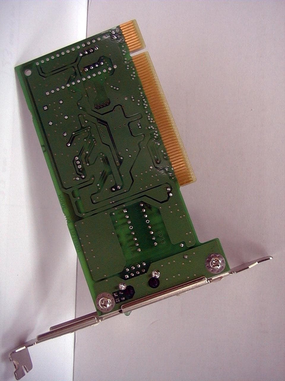
Click to zoom
Application Details
- Equipment Class
- JBP - Part 15 Class B Computing Device Peripheral
- Date of Grant
- Oct 25, 1999
- Application Purpose
- Original Equipment
- Date of Application
- Sep 28, 1999
- Equipment Note
- 10 X 100 M USB ETHERNET ADAPTER
- Company
- CIS Technology Inc
- Country
- Taiwan
Documents & Files
Document Text
Text extracted from the exhibit documents filed with the FCC. Open a document above to read the original.
Users Manual
EXHIBIT C User Manual 10/100Mbps Ethernet USB Adapter Installation Guide WS-U002TX 10/100Mbps Ethernet USB Adapter 1 FCC Compliance Statement This device complies with Part 15 of the FCC rules. Operation is subject to the following two conditions: (1) this device may not cause harmful interference, and (2) this device must accept any interference received, including interference that may cause un- desired operation. NOTE This equipment has been tested and found to com- ply with the limits for a Class B digital device, pursu- ant to Part 15 of the FCC rules. These limits are designed to provide reasonable protection against harmful interference in a residential installation. This equipment generates, uses and can radiate radio fre- quency energy and, if not installed and used in ac- cordance with the instructions, may cause harmful interference to radio communications. However, there is no guarantee that interference will not oc- cur in a particular installation. If this equipment does cause harmful interference to radio or televi- sion reception, which can be determined by turning the equipment off and on, the user is encouraged to try to correct the interference by one or more of the following measures: 10/100Mbps Ethernet USB Adapter 2 - Reorient or relocate the receiving antenna. - Increase the separation between the equipment and receiver. - Connect the equipment into an outlet on a circuit different from that to which the re- ceiver is connected. - Consult the dealer or an experienced radio / TV technician for help. CE Compliance Statement We hereby certify that the USB adapter complies with the EN 50081-1 and EN 50082-1 requirements. NOTE: EN 50081-1 standard : EN 55022 Class B (CISPR-22 Class B ) EN 50082-1 standard :IEC 801-2 (Electrostatic Discharge) :IEC 801-3 (Radiated Immunity) :IEC 801-4 (Electrical Fast Transient /Burst) All registered trademarks are the property of their respective owners. 10/100Mbps Ethernet USB Adapter 3 CONTENTS FCC Compliance Statement................... 1 CE Compliance Statement................... 2 Introduction................... 4 Summary of Features................... 4 Package Contents................... 5 LED Indicators................... 5 USB Cable................... 6 Network Driver................... 6 Installing the Adapter................... 7 Specifications................... 8 10/100Mbps Ethernet USB Adapter 4 Section 1 Introduction The 10/100Mbps Ethernet USB Adapter is designed in a convenience way to connect your PC to the 10BASE-T or 100BASE-TX network via the USB (Universal Serial Bus) interface. The device is equipped with a Type-B receptacle for the connection to the USB host or hub, and a RJ-45 receptacle to the 10BASE-T or 100BASE-TX Ethernet network. The USB adapter can source an operating power from the USB host or hub via a USB cable. Therefore, no external power adapter is required. In addition, this adapter is compliant with Windows 98 and above, the plug-and-play driver installation lets user easily install this adapter to Windows oper- ating system. Summary of Features * Compliant with the 10BASE-T and 100BASE- TX specifications of the IEEE 802.3 standard * Compliant with USB interface specification ver. 1.0/ 1.1 standard * One (1) RJ-45 port provides connection for 10BASE-T or 100BASE-TX network connection * One (1) Type-B receptacle provides connection for USB host or hub * No external power adapter is required 10/100Mbps Ethernet USB Adapter 5 Package Contents The package should contain the following items: PUSB adapter PUser's manual PUSB cable PDriver diskette If any item is missing or damaged, please contact your dealer for replacement. LED Indicators Your USB adapter provides the variety of informa- tive LEDs on the up panel for easy viewing and troubleshooting. This section will help you understand the LED indication, Figure 1-1 shows the outlook of the adapter. Figure 1-1 LED indicators of the adapter 10/100Mbps Ethernet USB Adapter 6 LNK/ ACT LED The green LED displays the link and activity status. If a good link is established on the port, this green LED will be continuously lit. When data is transmitted the green LED will flash. 100 LED The green LED displays the speed interface con- nection status. If a valid connection is detected via the USB interface and the driver is initialized properly, the green LED will be lit. USB Cable A USB cable , 64cm length totally,is equipped with a standard receptacle at each end respectively. Network Driver The driver diskette contains different network driver for different Network Operating Syetems. For more information about the drive installation, refer to README.TXT in the driver diskette. 10/100Mbps Ethernet USB Adapter 7 Section 2 Installing the Adapter The USB adapter is designed for Plug-and-Play installation, performing the steps as below to connect your USB adapter to the network. Step1Connect the one end of the USB cable to the Type-B receptacle of the USB adapter, and connect the other end (Type-A) to the PC's USB interface port, ensuring the connectors are fully engaged. Figure 2-1 Installing the adapter to a network application Step2 Connecting UTP cable Connect one end of a twisted-pair cable to the USB adapter's RJ-45 port, and the other end to an appropriate device with a 10Mbps or 100Mbps Ethernet interface . Type-A receptacle Type-B receptacle USB Cable USB Adapter PC USB Port 10 /100Mbps Network 10BAES-T and 100BASE-TX Port 10/100Mbps Ethernet USB Adapter 8 Section 3 Specifications IEEE 802.3 standards: 10BASE-T and 100BASE- TX USB standards: Ver. 1.0/1.1 Wiring Connector: RJ-45, Type-B receptacle Weight:50g (Adapter) 40g (Cable) Dimensions:78mm x 65mm x 29mm Cable Length:64 cm (w/ Connector) Emission Compliance: FCC Part 15 Class B EN 55022 Class B CISPR-22 Class B Immunity Compliance:IEC 801-2 (Electrostatic Discharge) IEC 801-3 (Radiated Immunity) IEC 801-4 (Electrical Fast Transient/Burst) Power Consumption: 110mA, @5V (Max.) Operating Temperature:0 to …
Text truncated - open the document above for the full version.
Block Diagram
EXHIBIT E Block Diagram
External Photos
EXHIBIT F Photographs of EUT
ID Label/Location Info
List of Exhibit EXHIBIT A Sample Label EXHIBIT B Test Report EXHIBIT C User Manual EXHIBIT D Circuit Diagram EXHIBIT E Block Diagram EXHIBIT F Photographs of EUT EXHIBIT A Sample Label LABEL Format: This device complies with Part 15 of the FCC Rules Operation is subject to the following two conditions: (1) This device may not cause harmful interference, and (2) This device must accept any interference received, including interference that may cause undesired operation. FCC ID : L4OU002TX Model No.: WS-U002TX LABEL Size : 4530 mm LABEL Position:
ID Label/Location Info
EXHIBIT A Sample Label LABEL Format: This device complies with Part 15 of the FCC Rules Operation is subject to the following two conditions: (1) This device may not cause harmful interference, and (2) This device must accept any interference received, including interference that may cause undesired operation. FCC ID: L4OU002TX Model No. :WS-U002TX LABEL Size : 45×30 mm LABEL Position:
ID Label/Location Info
EXHIBIT A Sample Label LABEL Format: This device complies with Part 15 of the FCC Rules Operation is subject to the following two conditions: (1) This device may not cause harmful interference, and (2) This device must accept any interference received, including interference that may cause undesired operation. FCC ID : L4OU002TX Model No. : WS-U002TX LABEL Size : 4530 mm LABEL Position:
Schematics
EXHIBIT D Circuit Diagram
Test Report
EXHIBIT B Test Report Test Report------------------------------------------------------------------------------------------------------------ Report No.: C0915655, Ethernet Card for PCI, FCC Part 15.109 (g), Class B Test date: 08/11/99, Training Research Co., Ltd., TEL: 886-2-26935155,Fax: 886-2-26934440 2/14 Contents Chapter 1Introduction Description of EUT........................................................................................................................3 Configuration of Test Setup............................................................................................................4 List of Support Equipment..............................................................................................................5 Chapter 2Conducted Emission Test Test Condition and Setup...............................................................................................................7 Conducted Test Placement.............................................................................................................8 Chapter 3Radiated Emission Test Test Condition and Setup...............................................................................................................9 Radiated Test Placement...............................................................................................................10 Appendix A: Conducted test result.....................................................................................................................11 Appendix B: Radiated test result........................................................................................................................12 Test Report------------------------------------------------------------------------------------------------------------ Report No.: C0915655, Ethernet Card for PCI, FCC Part 15.109 (g), Class B Test date: 08/11/99, Training Research Co., Ltd., TEL: 886-2-26935155,Fax: 886-2-26934440 3/14 Chapter 1 Introduction Description of EUT: The EUT is a data transmission / receiver facility. It is designed to connect with the IBM PC or compatible computer and makes your data equipment available to transmit / receive data via the EUT. During testing the EUT was operated at Tx or Rx mode for each emission measured. This was done in order to insure that maximum emission levels were attained. Connections of EUT: (1)The USB connector of EUT is connected with the USB B port of PC. (2)The RJ-45 jack of EUT is connected with a Lan card installed in a PC located remotely. Test method: When the measurement was taken, the following modes were tested: ‘‘10Mbps ’’ and ‘‘100Mbps ’’ Pretest was found that the emission of operating mode is worse than standby mode. So, The final test is made at the operating mode. During testing, the EUT was operated at “transmitting” and “receiving” mode simultaneously. The test placement as the photographs showed is the worst case emission placed. (If the emission is close to the ambient, the resolution BW and view resolution will be reduced and the data will be recorded by detection of maximum hold peak mode.) The testing configuration of test setup is showing in the next page. Test Report------------------------------------------------------------------------------------------------------------ Report No.: C0915655, Ethernet Card for PCI, FCC Part 15.109 (g), Class B Test date: 08/11/99, Training Research Co., Ltd., TEL: 886-2-26935155,Fax: 886-2-26934440 4/14 Configuration of test setup Connections: PC: *Serial A port --- a external modem with 76 cm long, shielded, RS-232 cable *Serial B port --- a shielded RS232 cable with 76cm long, no ferrite bead *Printer port --- a Printer with 1.2m length data cable *Keyboard port --- a Keyboard with 1m length data cable *Mouse port --- a Mouse with 0.7m long of data cable *Monitor port --- a monitor with 1m length data cable *USB A port --- a USB joystick with 1.5m long shielded, no ferrite bead data cable *USB B port --- EUT (Each port on PC is connected with suitable device) EUT: * UTP port--- a 20m long, non-shielded, no ferrite bead, RJ-45 cable to the Lan Card installed in a PC located remotely *USB connector --- via a 0.65m long, shielded, no ferrite core, USB ‘‘A-B’’ cable to the USB B port of PC. Modem Monitor Keyboard PC EUT Power Mouse Printer USB Joystick RS232 cable To far-end PC Test Report------------------------------------------------------------------------------------------------------------ Report No.: C0915655, Ethernet Card for PCI, FCC Part 15.109 (g), Class B Test date: 08/11/99, Training Research Co., Ltd., TEL: 886-2-26935155,Fax: 886-2-26934440 5/14 List of support equipment Conducted (Radiated) test: PC : ACER Model : M11E/H71-X35I19X Serial No. : TM12535 FCC ID : DOC Approval Power type : AC 100~120V, 50 ~60Hz, 5A / 200~240 VAC, 50 ~60Hz, 3A, Switching Power cord : non-Shielded, 1.7m long, Plastic, no ferrite core Monitor : HP Model No. : D2821 Serial No. : TW 73512262 (TW 73147163) FCC ID : A3KMO64 Power type : AC 110~120 / 220~240 VAC, Switching Power cord : Non-Shielded, 3m long, no ferrite core Data cable : Shielded, 1.8m long, with ferrite core Keyboard : Digital Model No. : KB-5923 Serial No. : 9S74904837 (9S74904665) FCC ID : E8HKB-5923 Power type : By PC Data cable : Shielded, 1.8m long, with ferrite core Printer : HP Model No. : C2642A Serial No. : SG69A196GV FCC ID : B94C2642X Power type : 220 VAC, 50Hz Power cord : Non-shielded, 2m long, no ferrite core Data cable : Shielded, 1.84m long, no ferrite core (1.7m) Test Report------------------------------------------------------------------------------------------------------------ Report No.: C0915655, Ethernet Card for PCI, FCC Part 15.109 (g), Class B Test date: 08/11/99, Training Research Co., Ltd., TEL: 886-2-26935155,Fax: 886-2-26934440 6/14 Modem : ACEEX Model No. : XDM-9624 FCC ID : IFAXDM-9624 Power type : 220VAC, 50Hz / 9VAC, 1A Power cord : Non-shielded, 1.9m long, no ferrite cord Data cable : RS232…
Text truncated - open the document above for the full version.
Contact Information
Applicant
Jenner Lin(Manager)
886 26987099Fax: 886 26982735
Technical Contact
Training Research Co., Ltd.Jeff Chiu
[email protected]886-2-26935155
2, Lane 194, Huan-Ho Street, Hsichih, · Taipei Hsien · Taiwan
Non-Technical Contact
Training Research Co., LtdJacky Wu
[email protected]886-2-26935155
Test Firm
Training Research Co., Ltd.Jack Tsai
Technical Specifications
| # | Rule Parts | Frequency Range | Power Output |
|---|---|---|---|
| 1 | 15B | - | - |
Other Applications from CIS Technology Inc
L4OWSAD80PST
Jun 20, 2000ADSL Modem
Equipment Class
JBP - Part 15 Class B Computing Device Peripheral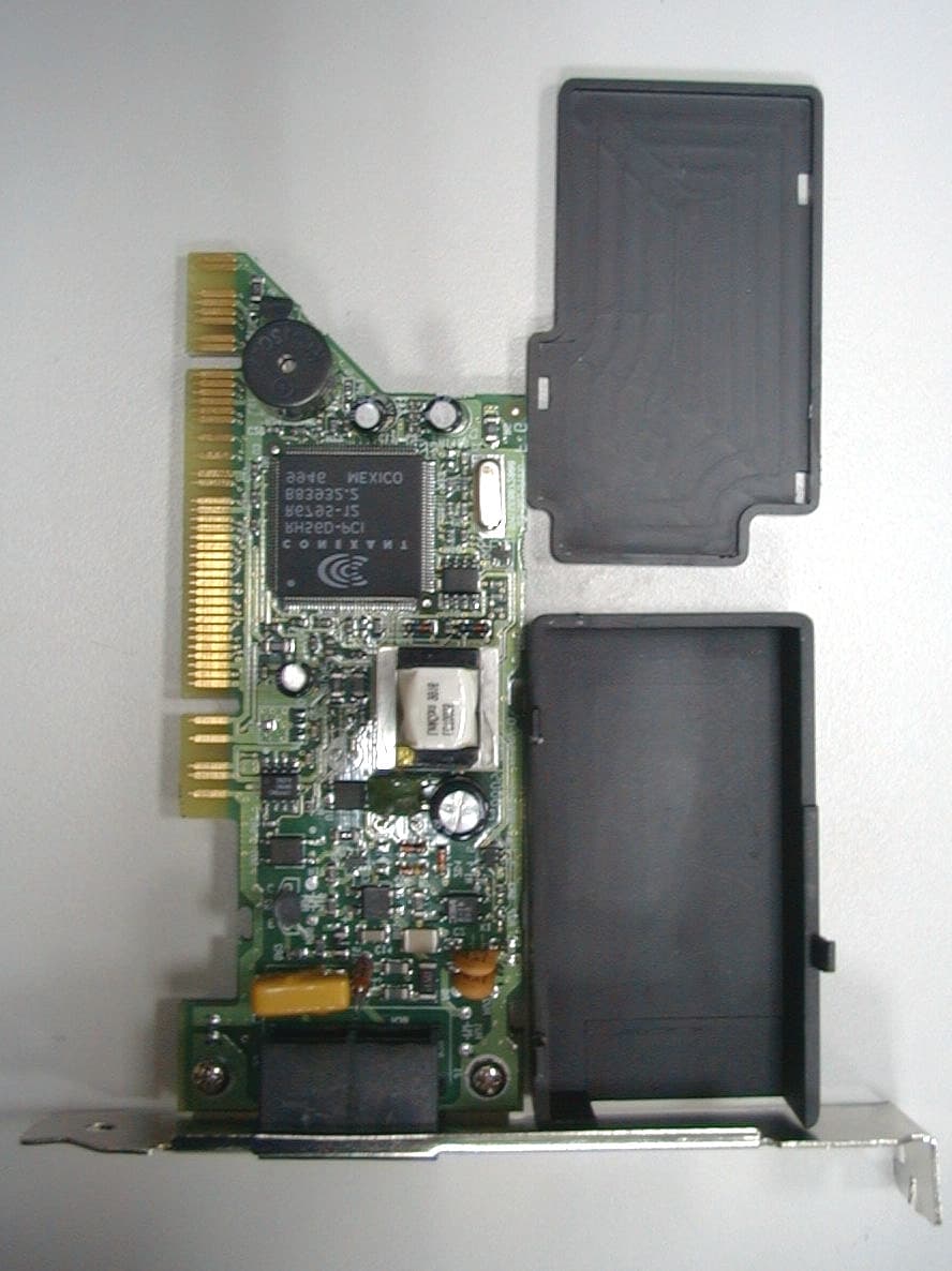
L4OWS-5614PMMU
Mar 28, 200056K Fax/Data/Voice Modem Card
Equipment Class
JBP - Part 15 Class B Computing Device Peripheral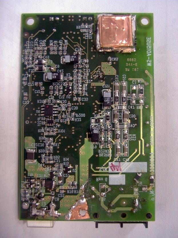
L4OWSAD15USE
Mar 26, 2000Centillium Optimizer USB ADSL Modem
Equipment Class
JBP - Part 15 Class B Computing Device Peripheral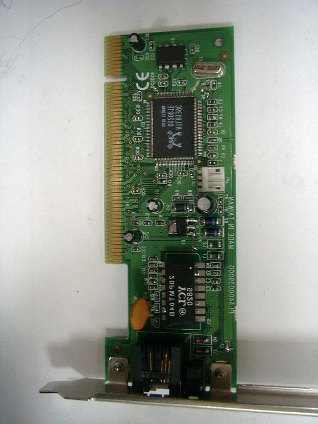
L4OR450
Mar 26, 200010/100BASE-TX Fast Ethernet Card for PCI
Equipment Class
JBP - Part 15 Class B Computing Device Peripheral
L4OWSAD35PSI
Mar 23, 2000ITeX Apoll II ADSL Modem
Equipment Class
JBP - Part 15 Class B Computing Device Peripheral