L5C0781TX-1Remote Sensor
Ansen Electronics Co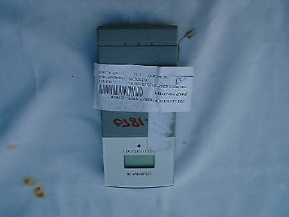
Click to zoom
Application Details
- Equipment Class
- DSC - Part 15 Security/Remote Control Transmitter
- Date of Grant
- Aug 25, 2003
- Application Purpose
- Original Equipment
- Date of Application
- Aug 25, 2003
- Equipment Note
- Remote Sensor
- Frequency Range
- 433.90000000 - 433.90000000
- Company
- Ansen Electronics Co
- Country
- Hong Kong
Documents & Files
Document Text
Text extracted from the exhibit documents filed with the FCC. Open a document above to read the original.
Users Manual
RF Remote Transmitter Ownerís Manual Model 0781 Lift off the bracket stand, loose the 4 screws with a small screwdriver, insert 2 pcs AAA batteries according to the polarity indicated. Replace the cover and tighten the 4 screws. SETTING UP THE WIRELESS THERMOMETER: !For the first installation, always insert batteries to the home unit and then the remote sensor. Your new RF Thermometer is build with random security code technology, the home unit will learn the random code of the first remote sensor and log in as channel 1. Channel 2 and Channel 3 will be registered in the same way. !The registered channels will be erased when the batteries of the remote sensor or the home unit are removed. !When replacing batteries for the remote sensor, remember to clear the corresponding channel of the home unit in this way: Select the respective channel y pressing the CHANNEL button, hold the CHANNEL button 3 seconds to clear the registration. !When replacing batteries for the home receiver, please remove batteries of all remote sensors and re-install the batteries to the sensors according to the desired channel sequence. !Press the Tx button on the back of remote sensor to verify the RF reception, hold the button 3 sec to reset. !To take temperature of water or extreme temperatures, use the plug-in wire probe. The temperature sensor inside the transmitter will be cut off automatically. C/ F SELECTION At normal mode, press ì C/ F ì button to select C and F. SPECIFICATIONS Range of temperature measurement: Remote sensor :-20C to 60C (-4F to 140F) Transmission: 30M (100 ft.) open area, RF434 MHz Accuracy: +-1.5 C for temp Resolution: 0.1 degree for temperature Battery life: 12 months for remote sensor (alkaline batteries recommended) Note: This equipment has been tested and found to comply with the limits for a Class B digital device, pursuant to Part 15 of the FCC Rules. These limits are designed to provide reasonable protection against harmful interference in a residential installation. This equipment generates, uses and can radiate radio frequency energy and, if not installed and used in accordance with the instructions, may cause harmful interference to radio communications. However, there is no guarantee that interference will not occur in a particular installation. If this equipment does cause harmful interference to radio or television reception, which can be determined by turning the equipment off and on, the user is encouraged to try to correct the interference by one or more of the following measures: - Reorient or relocate the receiving antenna. - Increase the separation between the equipment and receiver. - Connect the equipment into an outlet on a circuit different from that to which the receiver is connected. - Consult the dealer or an experienced radio/TV technician for help. Modifications not authorized by the manufacturer may void users authority to operate this device.
Block Diagram
0761TXF.sch-1 - Tue Jul 08 11:37:49 2003
External Photos
PHOTOGRAPH OF THE PRODUCT FRONT VIEW OF THE PRODUCT REAR VIEW OF THE PRODUCT
ID Label/Location Info
REMOTE SENSOR RF WIRELESS 0781-0 Housing Color (Front) : SILVER (751-336320) (Back) : Pantone 423C Gray (no spray) S I L V E R ( 7 5 1 - 3 3 6 3 2 0 ) LENS COLOR : Silver (silk screen on the back side) Pantone 423C Gray (no spray) Pantone 423C Gray Silk screen color : Pantone Cool Gray 11C This device complies with part 15 of the FCC Rules. Operation is subject to the following two conditions: (1) this device may not cause harmful interference, and (2) this device must accept any interference received, including interference that may cause undesired operations. FCC ID: L5C0781TX-1 MADE IN CHINA Silk screen color : White
Internal Photos
PHOTOGRAPH OF THE PRODUCT INNER CIRCUIT TOP VIEW INNER CIRCUIT BOTTOM VIEW
Operational Description
FCC ID: L5C0781TX-1 Circuit Description The 434MHz crystal oscillator drives the base of Q2 the final/buffer amplifier. The modulation provided by U1. The output of Q2 has the matching network consisting of L6 and C9 that limit the harmonic content and effect the proper coupling of the antenna to the output stage. Antenna, Ground and Power Source There is no external antenna. There is no external ground connection. The ground is only that of the printed circuit board. Electric current is supplied by a 3 Volt (“AA” size battery x 2) primary battery
Test Report
Date: 2003-07-16 TEST REPORT Page 1 of 24 No.: HM111101 FCC PART 15 SUBPART C CERTIFICATION REPORT FOR LOW POWER TRANSMITTER TEST REPORT No.:HM111101 Equipment Under Test [EUT]:Remote Sensor Model Number:0781 Applicant:Ansen Electronics Company FCC ID :L5C0781TX-1 Date: 2003-07-16 TEST REPORT Page 2 of 24 No.: HM111101 CONTENT: Cover Page 1 of 24 Content Page 2-3 of 24 Conclusion Page 4 of 24 1.0General Details 1.1Test Laboratory Page 5 of 24 1.2Applicant Details Page 5 of 24 Applicant HKSTC Code Number for Applicant Manufacturer 1.3Equipment Under Test [EUT] Page 6 of 24 Description of EUT operation 1.4Date of Order Page 6 of 24 1.5Submitted Sample Page 6 of 24 1.6Test Duration Page 6 of 24 1.7Country of Origin Page 6 of 24 1.8 Additional Information of EUT Page 7 of 24 2.0Technical Details 2.1Investigations Requested Page 8 of 24 2.2Test Standards and Results Summary Page 8 of 24 3.0Test Results 3.1Emission Page 9-14 of 24 3.2Bandwidth Measurement Page 15-16 of 24 Date: 2003-07-16 TEST REPORT Page 3 of 24 No.: HM111101 Appendix A List of Measurement Equipment Page 17 of 24 Appendix B Duty Cycle Correction During 100 msec Page 18-19 of 24 Appendix C Periodic Operation Page 20-21 of 24 Appendix D Photographs Page 23-24 of 24 Date: 2003-07-16 TEST REPORT Page 4 of 24 No.: HM111101 CONCLUSION The submitted product was deemed to have COMPLIED with the requirements of Federal Communications Commission [FCC] Rules and Regulations Part 15. The tests were performed in accordance with the standards described above and on Section 2.2 in this Test Report. Verified byPatrick Wong for Chief Executive Date: 2003-07-16 TEST REPORT Page 5 of 24 No.: HM111101 1.0General Details 1.1Test Laboratory The Hong Kong Standards and Testing Centre Ltd. EMC Laboratory 10 Dai Wang Street, Taipo Industrial Estate New Territories, Hong Kong Telephone:852 2666 1888 Fax:852 2664 4353 1.2Applicant Details Applicant ANSEN ELECTRONICS COMPANY Room 73-78, 2/F. Sino Industrial Plaza, 9 Kai Cheung Road, Kowloon Bay, Kowloon, Hong Kong. HKSTC Code Number for ApplicantANE001 Manufacturer ANSEN ELECTRONICS COMPANY Chen Tung Industrial Zone, Ning Tau Administrative District, Qiao Tau Zhen, Dongguan, Guangdong, China Date: 2003-07-16 TEST REPORT Page 6 of 24 No.: HM111101 1.3Equipment Under Test [EUT] Description of Sample Product:Remote Sensor Manufacturer:Ansen Electronics Company Brand Name:Ansen Model Number:0781 Input Voltage:3Vd.c (“AA” size battery x 2) 1.3.1Description of EUT Operation The Equipment Under Test (EUT) is an Ansen Electronics Company., Remote Sensor. The transmitter is an automatic transmitter. The EUT is to transmit RF signal while temperature measurement is changed. The EUT is for data transmission, Modulation by Data Code. Tape is pulses modulation. 1.4Date of Order 2003-07-08 1.5Submitted Sample(s): 2 Samples per model 1.6Test Duration 2003-07-14 1.7Country of Origin China Date: 2003-07-16 TEST REPORT Page 7 of 24 No.: HM111101 1.8Additional Information of EUT SubmittedNot Available User Manual Part List Circuit Diagram Printed Circuit Board [PCB] Layout Block diagram FCC ID Label Date: 2003-07-16 TEST REPORT Page 8 of 24 No.: HM111101 2.0Technical Details 2.1Investigations Requested Perform ElectroMagnetic Interference measurement in accordance with FCC 47CFR [Codes of Federal Regulations] Part 15 and ANSI C63.4:2000 for FCC Certification. 2.2Test Standards and Results Summary Tables EMISSION Results Summary Test ConditionTest RequirementTest MethodClass /Test Result SeverityPassFailedN/A Field Strength of Fundamental Emissions & Spurious Emissions FCC 47CFR 15.231eANSI C63.4:2000N/A Radiated Emissions, 30MHz to 1GHz FCC 47CFR 15.209ANSI C63.4:2000Class B Conducted Emissions on AC, 0.15MHz to 30MHz FCC 47CFR 15.207ANSI C63.4:2000Class B Note: N/A - Not Applicable Date: 2003-07-16 TEST REPORT Page 9 of 24 No.: HM111101 3.0Test Results 3.1Emission 3.1.1Radiated Emissions Test Requirement:FCC 47CFR 15.231e Test Method:ANSI C63.4:2000 Test Date:2003-07-14 Mode of Operation:On mode Test Method: The sample was placed 0.8m above the ground plane on the OATS *. Measurements in both horizontal and vertical polarities were performed. During the test, each emission was maximized by: having the EUT continuously working, investigate all operating modes, rotated about all 3 axis (X, Y & Z) to obtain worst position, manipulating interconnecting cables, rotating turntable, varying antenna height from 1m to 4m in both horizontal and vertical polarization. The emissions worst-case are shown in Test Results of the following pages. *:OATS [Open Area Test Site] located at HKSTC with a metal ground plane on filed with the FCC pursuant to section 2.948 of the FCC rules, with Registration Number: 90657. Test Setup: EUT distance = 3m Pre -Amplifier Receiver Turn Table Computer Ground plane Date: 2003-07-16 TEST REPORT Page 10 of 24 No.: HM111101 Limits for Field Strength of Fundamental Emissions [FCC 47CFR 15.231e]: Frequency Range of Fundamental Field Strength of Fundamental Emission [Peak] Field Strength of Fundamental Emission [Average] [MHz][μV/m][μV/m] 40.66-40.701,000100 70-13050050 130-174500 to 1,500 *50 to 150 * 174-2601,500150 260-4701,500 to 5,000 *150 to 500 * Above 4705,000500 ** Linear interpolations Where F is the frequency in MHz, the formula for calculating the maximum permitted fundamental field strengths are as follows: for the band 130-174 MHz, μV/m at meters=22.72727(F)-2454.545; for the band 260-470 MHz, μV/m at 3 meters =16.6667(F)-2833.3333. The maximum permissible unwanted emission level is 20dB below the maximum fundamental level. Results: CorrectionLimit **Antenna Factor @3mPolarity dB μ V/m μ V/m 433.9066.420.787.122646.443,983.5Vertical 867.8027.328.856.1638.34,398.3Vertical Field Strength Measured dB μ V/m μ V/m Field Strength of Fundamental Emissions Peak Value Frequency Level @3m Field Strength MHzdB μ V/m CorrectionLimit **Antenna Factor @3mPolarity dB μ V/m μ V/m 433.9048.620.769.32917.44,398.…
Text truncated - open the document above for the full version.
Test Setup Photos
TEST SET UP PHOTOGRAPH OF THE PRODUCT MEASUREMENT OF RADIATED EMISSION TEST SET UP
Contact Information
Applicant
Alvin Luo(QE Manager)
Test Firm
Hong Kong Standards & Testing Cen.Wilson Wong
Technical Specifications
| # | Rule Parts | Frequency Range | Power Output |
|---|---|---|---|
| 1 | 15.231(e) | 433.9 MHz - 433.9 MHz | - |
Other Applications from Ansen Electronics Co
L5CR088G2
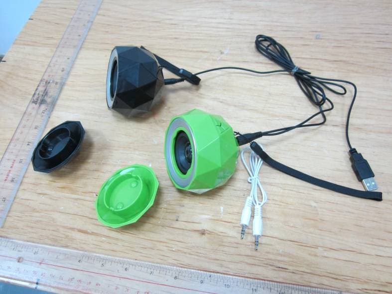
Jan 12, 2014Stereo Diamond Bluetooth Speaker/Stereo Powerball
Equipment Class
DSS - Part 15 Spread Spectrum Transmitter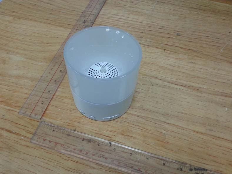
L5CR094G0
Nov 19, 2013Bluetooth Candle Light Speaker
Equipment Class
DSS - Part 15 Spread Spectrum TransmitterL5CR091GT
Sep 17, 2013BONE BLUETOOTH SPEAKER
Equipment Class
DSS - Part 15 Spread Spectrum TransmitterL5CR092GT
Sep 17, 2013X-CONCEPT BLUETOOTH SPEAKER
Equipment Class
DSS - Part 15 Spread Spectrum TransmitterL5CR080GT
Sep 17, 2013Candle Bluetooth Speaker
Equipment Class
DSS - Part 15 Spread Spectrum Transmitter