L5C0790-4TXDriveway Patrol(TX)
Ansen Electronics Co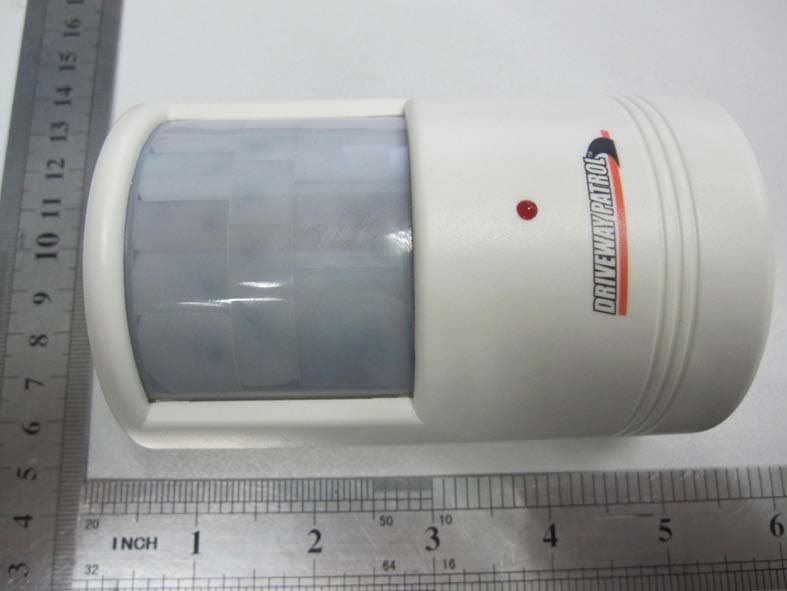
Click to zoom
Application Details
- Equipment Class
- DSC - Part 15 Security/Remote Control Transmitter
- Date of Grant
- May 26, 2011
- Application Purpose
- Original Equipment
- Date of Application
- May 26, 2011
- Equipment Note
- Driveway Patrol(TX)
- Frequency Range
- 433.92000000 - 433.92000000
- Company
- Ansen Electronics Co
- Country
- Hong Kong
Documents & Files
Document Text
Text extracted from the exhibit documents filed with the FCC. Open a document above to read the original.
Users Manual
PIR sensor range: 20 ̊ X 30 feet FCC Part 15 compliance Instructions Driveway Patrol Congratulations on purchasing the Driveway Patrol! Your set comes with a volume controlled Chime Unit and a Passive Infra-Red (PIR) Sensor. Both are battery operated. The Driveway Patrol system is simple to install and requires no wiring. Installing the Batteries: 1. The chime requires three C-size batteries (not included). To install the chime unit’s batteries, slide off compartment cover in direction of arrow and then install the receiver’s batteries. Be sure to observe correct polarity (+ and -) as marked inside the battery compartment. 2. The PIR sensor requires a 9V battery. To install the PIR sensor’s battery, unscrew the back cover of the sensor and insert the battery. Be sure to observe correct polarity (+ and -) as marked on the battery compartment. Operation: 1. Your Driveway Patrol Receiver Chime Unit has 3 settings (Hi or Lo Volume and Off). To switch the unit ON, select Hi or Lo Volume Settings. 2. Hang the PIR (Passive Infra Red) Sensor Unit at the entrance of your driveway (such as on a mailbox, on a tree or on a ground stake). You may also place the PIR Sensor on your garage, near the front entrance or rear door. Any movement nearby will transmit a signal to the Receiver Chime Unit triggering it to signal the chime. 3. Please ensure to place the PIR Sensor at least three feet high above the ground. 4. Receiver must be used indoors. Important Note: A) Whenever installing the PIR sensor the first time, the red LED on the PIR sensor may illuminate for about 60 seconds. To avoid receiving false alert, the door chime should be turned on after the first 60 seconds of the PIR sensor installation. B) In some applications the motion detector may be too sensitive, resulting in false alerts. To remedy this situation, put masking tape or labels on each side of the sensor window. Start on the sides and add an equal length of masking tape or labels to each side. Test the detector and add more covering if needed. Keep the band as narrow as 1/8” wide or wider depending on individual situation. Some trial and error may be required to find the optimal width. Specifications: Transmission Range; 400 feet (open area) Receiver: 3 X 1.5V “C-size” battery, not included Transmission frequency; 434MHz Transmitter: 1 X 9V battery, not included Battery Caution: 1. Do not mix alkaline, standard (carbon-zinc), or rechargeable (nickel-cadmium) batteries. 2. Non-rechargeable batteries are not to be recharged. 3. Never mix old and new batteries. 4. Make sure batteries are inserted with correct polarity. 5. Exhausted or dead batteries are to be removed from the unit. - Consult the dealer or an experienced radio/TV technician for help. - THE MANUFACTURER IS NOT RESPONSIBLE FOR ANY RADIO OR TV IN- TERFERENCECAUSED BY UNAUTHORIZED MODIFICATIONS TO THIS EQUIPMENT. SUCH MODIFICATIONS COULD VOID THE USER AUTHORITY TO OPERATE THE EQUIPMENT.
ID Label/Location Info
Label
Test Report
FCC TEST REPORT 47 CFR FCC Part 15 Subpart C & 15.231 FCC ID .............................................: L5C0790-4TX Report Reference No......................: WE11050004 Compiled by ( position+printed name+signature)..: File administrators Wenliang Li Supervised by ( position+printed name+signature)..: Test Engineer Tim Zhang Approved by ( position+printed name+signature)..: Manager Jeffrey Lu Date of issue.....................................: May 27, 2011 Testing Laboratory Name..............: Shenzhen Huatongwei International Inspection Co., Ltd Address ............................................: Keji Nan No.12 Road, Hi-tech Park, Shenzhen, China Applicant’s name............................: Ansen Electronics Company Address ............................................: ROOM 73-78,2/F., SINO INDUSTRIAL PLAZA, 9 KAL CHEUNG ROAD, KOWLOON BAY, KOWLOON, HONG KONG Manufacturer’s name.....................: Ansen Electronics Company Address ............................................: Chen Tung Industrial Zone,Ning Tau Administrative District, Qiao Tau Zhen, Dongguan, Guangdong Test specification: Standard ...........................................: 47 CFR FCC Part 15 Subpart C & 15.231 ANSI C63.10: 2009 TRF Originator..................................: Shenzhen Huatongwei International Inspection CO., Ltd Master TRF.......................................: Dated 2006-06 Shenzhen Huatongwei International Inspection Co., Ltd. All rights reserved. This publication may be reproduced in whole or in part for non-commercial purposes as long as the Shenzhen Huatongwei International Inspection Co., Ltd is acknowledged as copyright owner and source of the material. Shenzhen Huatongwei International Inspection Co., Ltd takes no responsibility for and will not assume liability for damages resulting from the reader’s interpretation of the reproduced material due to its placement and context. Equipment Under Test ...................: Driveway Patrol(TX) Trade Mark .......................................: / Model/Type reference.......................: 0790-4 Listed Models ..................................: / Result................................................: Complied V1.0 Page 2 of 23 Report No.: WE10050004 FCC ID:L5C0790-4TX Shenzhen Huatongwei International Inspection Co., Ltd T E S T R E P O R T Test Report No. : WE11050004 May 27, 2011 Date of issue Equipment under Test : Driveway Patrol(TX) Model /Type : 0790-4 Listed Models : / Applicant : Ansen Electronics Company Address : ROOM 73-78,2/F., SINO INDUSTRIAL PLAZA, 9 KAL CHEUNG ROAD, KOWLOON BAY, KOWLOON, HONG KONG Manufacturer : Ansen Electronics Company Address : Chen Tung Industrial Zone,Ning Tau Administrative District, Qiao Tau Zhen, Dongguan, Guangdong V1.0 Page 3 of 23 Report No.: WE10050004 FCC ID:L5C0790-4TX Shenzhen Huatongwei International Inspection Co., Ltd Contents 1. TEST STANDARDS .................................................................. 4 2. SUMMARY............................................................................. 5 2.1. General Remarks 5 2.2. Equipment under test power supply 5 2.3. Short description of the Equipment under Test (EUT) 5 2.4. EUT operation mode 5 2.5. Related submittal(s) / Grant (s) 5 2.6. Modifications 5 2.7. Block Diagram of Test Setup 6 2.8. Summary of standards and result 6 3. TEST ENVIRONMENT............................................................... 7 3.1. Address of the test laboratory 7 3.2. Test Facility 7 3.3. Environmental conditions 8 3.4. Statement of the measurement uncertainty 8 3.5. Equipments Used during the Test 9 4. TEST CONDITIONS AND RESULTS ............................................ 10 4.1. AC Conducted Emission 10 4.2. Radiated Emission 11 4.3. Deactivation Time 16 4.4. 20dB Bandwidth 17 4.5. Antenna Requirement 18 5. TEST SETUP PHOTOS OF THE EUT .......................................... 19 6. EXTERNAL AND INTERNAL PHOTOS OF THE EUT ....................... 21 V1.0 Page 4 of 23 Report No.: WE10050004 FCC ID:L5C0790-4TX Shenzhen Huatongwei International Inspection Co., Ltd 1. TEST STANDARDS The tests were performed according to following standards: 47 CFR FCC Part 15 Subpart C & 15.231 – Intentional Radiators & Periodic operation in the band 40.66–40.70 MHz and above 70 MHz ANSI C63.10: 2009 – American National Standard for Teating Unlicensed Wireless Devices V1.0 Page 5 of 23 Report No.: WE10050004 FCC ID:L5C0790-4TX Shenzhen Huatongwei International Inspection Co., Ltd 2. SUMMARY 2.1. General Remarks Date of receipt of test sample : May 08, 2011 Testing commenced on : May 08, 2011 Testing concluded on : May 27, 2011 2.2. Equipment under test power supply Power supply voltage : ○ 120V / 60 Hz ○ 115V / 60Hz ○ 12 V DC ○ 24 V DC ● Other (specified in blank below) DC 9V from battery 2.3. Short description of the Equipment under Test (EUT) Product Name : Driveway Patrol(TX) Model Number : 0790-4 Operation Frequency : 433.92MHz Modulation Technology : ASK Transmitter Type : Periodic Transmitter Sample Type : Prototype I/O Port : / For more details, refer to the user’s manual of the EUT. 2.4. EUT operation mode The EUT has been tested under typical operating condition. 2.5. Related submittal(s) / Grant (s) This submittal(s) (test report) is intended for FCC ID: L5C0790-4TX filing to comply with the FCC Part 15, Subpart C Rules. 2.6. Modifications No modifications were implemented to meet testing criteria. V1.0 Page 6 of 23 Report No.: WE10050004 FCC ID:L5C0790-4TX Shenzhen Huatongwei International Inspection Co., Ltd 2.7. Block Diagram of Test Setup Note: For actual sample please see test setup photos and EUT external photos. 2.8. Summary of standards and result FCC Rules Description of Test Result §15.207 (a) Conducted Emissions N/A §15.205, §15.209, 15.35 (c), §15.231 (b) Radiated Emissions Compliant §15.231(a) Deactivation Testing Compliant §15.231(c) 20 dB Band Width Testing Compliant §15.203 Antenna Requirement Compliant NOTE: 1) The detailed test rusult ple…
Text truncated - open the document above for the full version.
Contact Information
Applicant
Alvin Luo(QE Manager)
Test Firm
Shenzhen Huatongwei International Insp. Co., LtdMoffy Yu
Technical Specifications
| # | Rule Parts | Frequency Range | Power Output |
|---|---|---|---|
| 1 | 15.231 | 433.92 MHz - 433.92 MHz | - |
Other Applications from Ansen Electronics Co
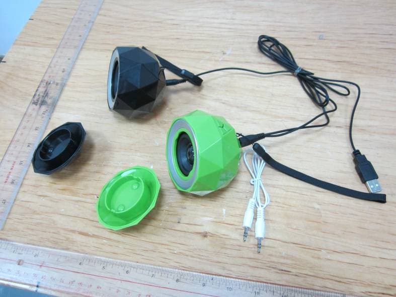
L5CR088G2
Jan 12, 2014Stereo Diamond Bluetooth Speaker/Stereo Powerball
Equipment Class
DSS - Part 15 Spread Spectrum Transmitter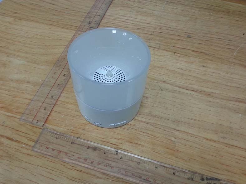
L5CR094G0
Nov 19, 2013Bluetooth Candle Light Speaker
Equipment Class
DSS - Part 15 Spread Spectrum TransmitterL5CR091GT
Sep 17, 2013BONE BLUETOOTH SPEAKER
Equipment Class
DSS - Part 15 Spread Spectrum TransmitterL5CR092GT
Sep 17, 2013X-CONCEPT BLUETOOTH SPEAKER
Equipment Class
DSS - Part 15 Spread Spectrum TransmitterL5CR080GT
Sep 17, 2013Candle Bluetooth Speaker
Equipment Class
DSS - Part 15 Spread Spectrum Transmitter