L5C0964TXWeather Station
Ansen Electronics Co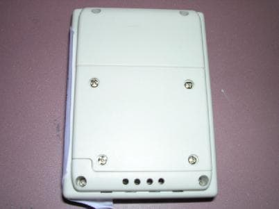
Click to zoom
Application Details
- Equipment Class
- DSC - Part 15 Security/Remote Control Transmitter
- Date of Grant
- Aug 03, 2004
- Application Purpose
- Original Equipment
- Date of Application
- Aug 03, 2004
- Equipment Note
- Weather Station
- Frequency Range
- 433.90000000 - 433.90000000
- Company
- Ansen Electronics Co
- Country
- Hong Kong
Documents & Files
Document Text
Text extracted from the exhibit documents filed with the FCC. Open a document above to read the original.
Users Manual
WIRELESS WEATHER STATION 0964 Owner’s Manual Thank you for purchasing the new generation electronic weather station. Designed and engineered with the state-of-art technology and components, this instrument will provide accurate and reliable measurement of air pressure, in/out temperature and humidity together with WWVB. Read this manual carefully to full explore the sophisticated features and functions of the new product. Name and Functions of Buttons: Press Functions Hold 3 seconds CHANNEL Select Channel 1,2,3 Delete current channel SET ZONE Time Enter clock & calendar setting + 1 step forward Fast advance Alarm 1, Alarm 2 on/ off - 1 step backward Fast backward Manual synchronization MAX/ MIN View max & min memory for temperature & humidity (hold to select C/F) CLEAR Clear memory at Max/ Min display Weather Offset AL Read ALARM TIME 1, 2 Set ALARM TIME 1, 2 - Press any key to stop alarm when alarm sounds BATTERY INSTALLATION Home Receiver : Lift off the battery cover at the back, install 2 pcs AA batteries according to the polarity indicated, close the battery cover. Remote Sensor : Lift off the bracket stand, loose the 4 screws with a small screwdriver, insert 2 pcs AAA batteries according to the polarity indicated. CH button: Slide to CH 1 for the first sensor C/F button: Select viewing C or F Tx button: Press to trigger a manual transmission After selecting the desired modes, replace the cover and tighten the 4 screws. SET UP: Enter the Existing Weather Condition into your Weather Station l Install batteries into the home unit and it will ask you to enter the existing weather condition. Press “MAX/ MIN” to select the a weather condition (Sunny, Partial Sunny, Cloudy, Rainy, Stormy), press “CLEAR” to confirm the setting. The built-in barometer will be automatically offset in this setting. Seeking WWVB l The clock will start to seek for the time signal after installing batteries. If radio time signal is available, the correct time and date will appear in around 2.5 to 5 minutes. RADIO-CONTROLLED CLOCK The unit will start synchronizing the clock before registering the RF thermometer. Insert batteries into the remote sensor after the clock received the DCF time. The Tower icon will flash regularly during synchronization. Signal strength level is indicated in this way: 1.Very Weak or no signal 2. Weak 3. Good 4. Icon appear fixed (Reception successful) 5. Icon out If signal level is weak and time reception is not successful, move the unit away the source of interference and try again in another location with better radio signal. The R/C clock will have a daily synchronization at 01:00 everyday. If not successful, the R/C clock will seek for time signal every hour. Each R/C reception cycle around 2 minutes to 5 minutes. To avoid interference, the unit will disable the buttons functions during radio time reception. This is not a defect. Simply press “ – “ button to turn radio time reception temporarily off. Setting up Remote Sensor l Install batteries into the remote sensor. Press the “TX” key to trigger a transmission. The outdoor temperature and humidity section will appear on the home unit. Always set the first sensor to CH 1. Maximum three sensors can be registered. One sensor is included in this package. l To verify transmission, press the Tx button of the remote sensor. The red LED on the remote sensor will flash when it transmit a signal. Temperature and humidity of the remote sensor will be updated and displayed on the remote sensor. l When replacing batteries for the remote sensor, remember to clear the corresponding channel of the home unit in this way: Select the respective channel by pressing the CH button, hold the CH button 3 seconds to clear the registration. Removing the batteries on the home unit can also clear all settings and registrations. C/ F SELECTION on the home unit Hold “MAX/MIN” button 3 seconds to select C and F WEATHER FORECAST with Storm Alert The built-in precision pressure sensor will read the atmospheric pressure and calculate the weather condition of the next 12 hours. The resolution: Sunny, Partial Sunny, Cloudy, Rainy, Stormy, Icy OFFSETTING AIR PRESSURE FOR WEATHER FORECAST To ensure accurate weather forecast under different altitude of your location, user should enter the existing weather condition. The unit will memorize the existing weather condition with the current air pressure level. The home unit will ask you to enter the existing weather condition right after installing batteries, please select the correct weather condition by pressing “ MAX/MIN “ and press “CLEAR” to enter. The home unit will try to seek for a remote sensor after the weather condition is being entered. After the initial setup, in case the weather forecast deviates from the existing conditions, you can still change the weather offset in the way: 1. Hold “ CLEAR ” button for 3 seconds to enter the pressure offset mode. The weather icon will flash. 2. Select the existing weather condition by pressing “ MAX/ MIN “. 3. Press “ CLEAR “ to confirm and exit. CLOCK & CALENDAR SETTING Hold “ CLK/CAL “ button for 3 seconds to enter clock set. Using “ + , - “ to adjust and “ CLK/CAL ” to confirm, the following values can be set in sequence: 12/ 24 hr > Year > Month > Date > Hour > Minutes > ZONE Time (Enter + - 12 hr in hour offset for different time zones, leave offset to 0 for home time) Press SET/ ZONE to select home time and ZONE Time PRESSURE, TEMPERATURE, HUMIDITY TREND INDICATORS The 3 small arrow icons will indicate: Rising, Steady, Falling. Refresh rate is every hour. MOON PHASE The current moon phase is displayed automatically. ALARM 1, ALARM 2 SETTING Select AL 1 or AL 2 by pressing the AL key. Hold “ AL “ for 3 seconds. Press “ +, - “ to enter the desired value and press “AL “ to confirm setting. To view alarm time 1 and 2, simply press “AL” button to read AL 1 and AL 2. The alarm time will display for 5 seconds and resume to normal clock thereafter. To turn AL 1, AL 2 on and o…
Text truncated - open the document above for the full version.
Block Diagram
0964TXF.sch-1 - Wed Jul 02 09:31:02 2003
External Photos
PHOTOGRAPH OF THE PRODUCT FRONT VIEW OF THE PRODUCT REAR VIEW OF THE PRODUCT
ID Label/Location Info
FCC ID : L5C0964TX This device complies with part 15 of the FCC rules. Operation is subject to the following two conditions; (1) this device may not cause harmful interference and (2) this device must accept any interference received, including interference that may cause undesired operation. AAA 1.5V AAA 1.5V Made in China TXC/F 1 2 3 0964
Internal Photos
PHOTOGRAPH OF THE PRODUCT INNER CIRCUIT TOP VIEW INNER CIRCUIT BOTTOM VIEW
Operational Description
FCC ID: L5C0964TX Circuit Description The 433MHz crystal oscillator drives the base of Q4 the final/buffer amplifier. The modulation provided by IC. The output of Q2 has the matching network consisting of L6, C8 and C9 that limit the harmonic content and effect the proper coupling of the antenna to the output stage. Antenna, Ground and Power Source There is no external antenna. There is no external ground connection. The ground is only that of the printed circuit board. Electric current is supplied by a 3 Volt (“AAA” size battery x 2) primary battery
Schematics
0964TX.sch-1 - Wed Jul 02 09:30:35 2003
Test Report
香 港 標 準 及 檢 定 中 心 Hong Kong Standards and Testing Centre Date : 2004-07-27 TEST REPORT Page 1 of 22 No. : HM150196 This report shall not be reproduced unless with prior written approval from the Hong Kong Standards and Testing Centre. 香港新界大埔工業村大宏街10號 10 Dai Wang Street, Taipo Industrial Estate, N.T., Hong Kong Tel: (852) 2666 1888 Fax: (852) 2664 4353 Homepage: www.hkstc.org E-mail: [email protected] For full text of “Conditions of Issuance of Test Report”, please refer to overleaf or refer to the website of STC: www.hkstc.org (the section “Application and Quotation”). Applicant: Ansen Electronics Company Room 73-78, 2/F, Sino, Industrial Plaza, 9 KAI Cheung Road, Kowloon Bay, Kowloon, Hong Kong Description of Samples: Model name: Weather Station Model no.: 0964Tx Brand name: Ansen FCC ID: L5C0964TX Date Samples Received: 2004-02-27 Date Tested: 2004-03-10 Investigation Requested: FCC Part 15 Subpart C Conclusions: The submitted product COMPLIED with the requirements of Federal Communications Commission [FCC] Rules and Regulations Part 15. The tests were performed in accordance with the standards described above and on Section 2.2 in this Test Report. Remarks: ---- K C Lee, EMC for Chief Executive 香 港 標 準 及 檢 定 中 心 Hong Kong Standards and Testing Centre Date : 2004-07-27 TEST REPORT Page 2 of 22 No. : HM150196 香港新界大埔工業村大宏街10號 10 Dai Wang Street, Taipo Industrial Estate, N.T., Hong Kong Tel: (852) 2666 1888 Fax: (852) 2664 4353 Homepage: www.hkstc.org E-mail: [email protected] For full text of “Conditions of Issuance of Test Report”, please refer to overleaf or refer to the website of STC: www.hkstc.org (the section “Application and Quotation”). CONTENT: Cover Page 1 of 22 Content Page 2-3 of 22 1.0 General Details 1.1 Test Laboratory Page 5 of 22 1.2 Applicant Details Page 5 of 22 Applicant HKSTC Code Number for Applicant Manufacturer 1.3 Equipment Under Test [EUT] Page 6 of 22 Description of EUT operation 1.4 Date of Order Page 6 of 22 1.5 Submitted Sample Page 6 of 22 1.6 Test Duration Page 6 of 22 1.7 Country of Origin Page 6 of 22 1.8 Additional Information of EUT Page 7 of 22 2.0 Technical Details 2.1 Investigations Requested Page 8 of 22 2.2 Test Standards and Results Summary Page 8 of 22 3.0 Test Results 3.1 Emission Page 9-12 of 22 3.2 Bandwidth Measurement Page 13-14 of 22 香 港 標 準 及 檢 定 中 心 Hong Kong Standards and Testing Centre Date : 2004-07-27 TEST REPORT Page 3 of 22 No. : HM150196 香港新界大埔工業村大宏街10號 10 Dai Wang Street, Taipo Industrial Estate, N.T., Hong Kong Tel: (852) 2666 1888 Fax: (852) 2664 4353 Homepage: www.hkstc.org E-mail: [email protected] For full text of “Conditions of Issuance of Test Report”, please refer to overleaf or refer to the website of STC: www.hkstc.org (the section “Application and Quotation”). Appendix A List of Measurement Equipment Page 15 of 22 Appendix B Duty Cycle Correction During 100 msec Page 16-17 of 22 Appendix C Periodic Operation Page 18-20 of 22 Appendix D Photographs Page 21-22 of 22 香 港 標 準 及 檢 定 中 心 Hong Kong Standards and Testing Centre Date : 2004-07-27 TEST REPORT Page 4 of 22 No. : HM150196 香港新界大埔工業村大宏街10號 10 Dai Wang Street, Taipo Industrial Estate, N.T., Hong Kong Tel: (852) 2666 1888 Fax: (852) 2664 4353 Homepage: www.hkstc.org E-mail: [email protected] For full text of “Conditions of Issuance of Test Report”, please refer to overleaf or refer to the website of STC: www.hkstc.org (the section “Application and Quotation”). 1.0 General Details 1.1 Test Laboratory The Hong Kong Standards and Testing Centre Ltd. EMC Laboratory 10 Dai Wang Street, Taipo Industrial Estate New Territories, Hong Kong Telephone: 852 2666 1888 Fax: 852 2664 4353 1.2 Applicant Details Applicant Ansen Electronics Company Room 73-78, 2/F, Sino, Industrial Plaza, 9 KAI Cheung Road, Kowloon Bay, Kowloon, Hong Kong HKSTC Code Number for Applicant ANE001 Manufacturer Ansen Electronics Company Chen Tung Industrial Zone, Ning Tau Administrative District, Qiao Tau Zhen, Dongguan, Guangdong, China. 香 港 標 準 及 檢 定 中 心 Hong Kong Standards and Testing Centre Date : 2004-07-27 TEST REPORT Page 5 of 22 No. : HM150196 香港新界大埔工業村大宏街10號 10 Dai Wang Street, Taipo Industrial Estate, N.T., Hong Kong Tel: (852) 2666 1888 Fax: (852) 2664 4353 Homepage: www.hkstc.org E-mail: [email protected] For full text of “Conditions of Issuance of Test Report”, please refer to overleaf or refer to the website of STC: www.hkstc.org (the section “Application and Quotation”). 1.3 Equipment Under Test [EUT] Description of Sample Product: Weather Station Manufacturer: Ansen Electronics Company Brand Name: Ansen Model Number: 0964Tx Input Voltage: 3Vd.c (“AAA” size battery x 2) 1.3.1 Description of EUT Operation The Equipment Under Test (EUT) is an Ansen Electronics Company., Weather Station. The transmitter is an automatic transmitter. The EUT is to transmit RF signal while temperature measurement is changed. The EUT is for data transmission, Modulation by Data Code. Tape is pulses modulation. 1.4 Date of Order 2004-02-27 1.5 Submitted Sample(s): 1 Sample per model 1.6 Test Duration 2004-03-10 1.7 Country of Origin China 香 港 標 準 及 檢 定 中 心 Hong Kong Standards and Testing Centre Date : 2004-07-27 TEST REPORT Page 6 of 22 No. : HM150196 香港新界大埔工業村大宏街10號 10 Dai Wang Street, Taipo Industrial Estate, N.T., Hong Kong Tel: (852) 2666 1888 Fax: (852) 2664 4353 Homepage: www.hkstc.org E-mail: [email protected] For full text of “Conditions of Issuance of Test Report”, please refer to overleaf or refer to the website of STC: www.hkstc.org (the section “Application and Quotation”). 1.8 Additional Information of EUT Submitted Not Available User Manual Part List Circuit Diagram Printed Circuit Board [PCB] Layout Block diagram FCC ID Label 香 港 標 準 及 檢 定 中 心 Hong Kong Standards and Testing Centre Date : 2004-07-27 TEST REPORT Page 7 of 22 No. : HM150196 香港新界大埔工業村大宏街10號 10 Dai Wang Street, Taipo Industrial Estate, N.T., Hong Kong Tel: (852) 2666 1888 Fax: (852) 2664 4353 Homepage: www.hkstc.org E-mail: [email protected] For full te…
Text truncated - open the document above for the full version.
Test Setup Photos
TEST SET UP PHOTOGRAPH OF THE PRODUCT MEASUREMENT OF RADIATED EMISSION TEST SET UP
Contact Information
Applicant
Alvin Luo(QE Manager)
Test Firm
Hong Kong Standards & Testing Cen.Wilson Wong
Technical Specifications
| # | Rule Parts | Frequency Range | Power Output |
|---|---|---|---|
| 1 | 15.231(e) | 433.9 MHz - 433.9 MHz | - |
Other Applications from Ansen Electronics Co
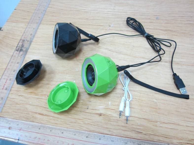
L5CR088G2
Jan 12, 2014Stereo Diamond Bluetooth Speaker/Stereo Powerball
Equipment Class
DSS - Part 15 Spread Spectrum Transmitter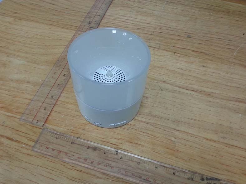
L5CR094G0
Nov 19, 2013Bluetooth Candle Light Speaker
Equipment Class
DSS - Part 15 Spread Spectrum TransmitterL5CR091GT
Sep 17, 2013BONE BLUETOOTH SPEAKER
Equipment Class
DSS - Part 15 Spread Spectrum TransmitterL5CR092GT
Sep 17, 2013X-CONCEPT BLUETOOTH SPEAKER
Equipment Class
DSS - Part 15 Spread Spectrum TransmitterL5CR080GT
Sep 17, 2013Candle Bluetooth Speaker
Equipment Class
DSS - Part 15 Spread Spectrum Transmitter