L5CW132TX-QWireless wind meter with thermo-hygrometer
Ansen Electronics Co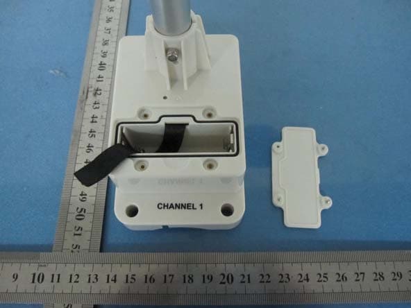
Click to zoom
Application Details
- Equipment Class
- DXX - Part 15 Low Power Communication Device Transmitter
- Date of Grant
- Sep 27, 2011
- Application Purpose
- Original Equipment
- Date of Application
- Sep 27, 2011
- Equipment Note
- Wireless wind meter with thermo-hygrometer
- Frequency Range
- 915.00000000 - 915.00000000
- Company
- Ansen Electronics Co
- Country
- Hong Kong
Documents & Files
Document Text
Text extracted from the exhibit documents filed with the FCC. Open a document above to read the original.
Users Manual
7” TFT WIRELESS PROFESSIONAL WEATHER STATION & PHOTO ALBUM Owner’s Manual Thank you for purchasing the new generation of 7” TFT weather station & photo album. Designed and engineered with the state-of-art technology and components, this instrument will provide accurate and reliable measurement of weather forecast, wind speed/direction, rainfall and indoor/outdoor temperature/humidity as well as a digital photo album. Read this manual carefully to fully explore the features and functions of the new product. The package includes - Photo Frame (Main unit) - Infrared (IR) remote control - Wind meter (built-in thermo-hygrometer) - Rain gauge - Adapter Additional tools needed for installation - Small Phillips screwdriver - Hexagonal Key - Electric drill - Pencil - Level - Mast, 1 – 1.25 inch (2.54 – 3.18 cm) in diameter (to mount the anemometer) Buttons on the photo frame Press Functions POWER Turn on or off the unit UP/DOWN Move up or down in the setup mode LEFT/RIGHT Select photos or move left or right in the SETUP mode Enter Enter the display mode or confirm setting in setup mode Exit Exit the current display mode (When display is off, press any buttons except [POWER] to turn on the weather display mode for around 1 minute) Buttons on the IR remote control Press Functions POWER Turn on or off the unit PHOTOS Enter photo mode WEATHER Enter weather mode WEATHER + PHOTOS Enter weather & photo mode CALENDAR Enter calendar mode SETUP Enter setup mode SLIDESHOW Enable or disable slideshow function (only available in photo mode) MENU Enter menu mode ENTER Enter the display mode or confirm setting in setup mode Exit Exit the current display mode UP/DOWN Move up or down in the setup mode LEFT/RIGHT Select photos or move left or right in the display mode ZOOM Zoom in the photo ROTATE Rotate the photo (When display is off, Press any buttons except [POWER] on the remote control to turn on display for around 1 minute) INTITIAL SETUP BATTERY & ADAPTER INSTALLATION Photo Frame : Main Power Source: Plug in the 5.0V adapter into the adapter socket on the right for basic operation IR Remote Control Battery (CR2025) is included in the IR remote control. For initial setup, pull out the battery insulation sheet from the bottom of the IR remote control. To replace the battery, follow the instruction on the back of the IR remote control to pull out the battery door. Follow the battery polarity and replace a new CR2025 battery. Close the battery door. Installation The weather station operates at 915MHz and does not require wire installation among the component parts. To ensure successful installation and the best performance, we recommend you follow the installation instructions in the order they appear in this manual. 1. Selecting a location for the anemometer Select a mounting location for the anemometer that is: - Outdoors, not blocked on top or sides, so wind can freely reach the anemometer - Within 75 meter open area from the monitor. Reduce distance if obstacles is between the anemometer & the monitor The best location for the anemometer is usually mounted on a mast in an open area where wind is not blocked on top or sides, or above roof level on the building where the monitor is located. 2. Mounting the anemometer Important: Before mounting, be sure the monitor & anemometer are within the effective transmission range. Note: To mount the anemometer, you need a mast (not supplied) about 1 – 1.25 inches (2.54 – 3.1 cm) in diameter, and the hardware necessary to fasten it to the mounting location. If you previously installed such a mast (for mounting antenna, for example), you can mount the anemometer on that mast. 1. If necessary, mount and ground a mast as directed in the instructions provided by the mast. 2. Place the supplied U-shape metal plates around the mast. Insert 4 pieces of the supplied Hex screws through the holes of the U-shape plates and the holes on the anemometer’s mounting bracket. (The wind vane is above the wind cup and the metal bar of the anemometer is in horizontal level) 3. Tighten the supplied Hex nut onto both ends of each screw 4. Calibrating the anemometer & installing batteries After mounting the anemometer, follow these steps to calibrate the wind direction so that the anemometer properly measures the wind direction and transmit to the monitor. Be sure battery has been removed from the anemometer before the calibration. Important: The same calibration is needed for the first set up and every battery replacement. 1. After mounting the anemometer, loosen the screws on the battery door with a small screwdriver and open the battery door. 2. Use the compass on the anemometer and turn the wind vane so it is pointing due north. 3. Hold the wind vane pointing due north and do not allow it to turn. Insert 2 pieces of AA batteries according to the polarity indicated. The red LED indicator above the battery cover of the anemometer will flash few times right after battery installation. Be sure the vane is pointing due north at the moment when red LED flashes and the calibration is now completed. Replace the battery cover and tighten the screws. 4. If the wind vane is not pointing due north when the red LED first flashes, remove batteries and repeat step 2 & 3. 5. Go to “SET UP” mode, select “SEARCH NOW” in the “WIRELESS SENSOR RECEPTION” section and exit. Wind direction, wind speed, wind chill & channel-1 temperature/humidity readings will appear within 2 minutes if the RF transmission is successful. 6. If the wind reading does not appear after 2 minutes of searching, the RF transmission is failed. Shorten the distance between the monitor & wind meter and search for the sensor again. If the RF transmission still failed, then shorten the distance again and reset the wind meter by removing all batteries from the wind meter and wait for 10 seconds before re-installing the batteries again. Then repeat above step until the RF communication is completed. 5. Selecting a location for the rain gauge Se…
Text truncated - open the document above for the full version.
Cover Letter(s)
Federal Communications Commission Authorization and Evaluation Division Date:201 1-9-19 Confidentiality Request regarding application for certification of FCC ID: L5CW 132TX-Q Pursuant to Sections 0.457 and 0.459 of the Commission’s Rules, we hereby request confidential treatment of information accompanying this application as outlined below: 1.Schematic 2.Theory of Operation 3.Block Diagram The above materials contain trade secrets and proprietary information not customarily released to the public. The public disclosure of these materials may be harmful to the applicant and provide unjustified benefits to its competitors. The applicant understands that pursuant to Section 0.457 of the Rules, We do not want these documents to be accessible to the general public. Sincerely, (ټ֮Գټ亜):Alice (亜ټԳ侴㲯):Executive Secretary Ansen Electronics Company Tel: (852)-2795-9473 Fax: (852)2751-6577 Web site:www.ansen.com.hk E-mail: [email protected]
ID Label/Location Info
W132-Q LOGO SIZE:27X6.4MM LOGO COLOR:BLACK silkscreen color :black FCC ID No. : L5CW132TX-Q Model No.: W132-Q Made In China FCC ID No. : L5CW132TX-Q Model No.: W132-Q Made In China This device complies with part 15 of the FCC Rules. Operation is subject to the following two conditions: (1) this device may not cause harmful interference, and (2) this device must accept any interference received, including interference that may cause undesired operation.
Test Report
FCC TEST REPORT 47 CFR FCC Part 15.249 Report Reference No......................: FCC ID..............................................: WE11090011 L5CW132TX-Q Compiled by ( position+printed name+signature)..: File administrators Wenliang Li Supervised by ( position+printed name+signature)..: Test Engineer Eric Zhang Approved by ( position+printed name+signature)..: Manager Jeffrey Lu Date of issue.....................................: Sep 21, 2011 Testing Laboratory Name..............: Shenzhen Huatongwei International Inspection Co., Ltd Address.............................................: Keji Nan No.12 Road, Hi-tech Park, Shenzhen, China Applicant’s name............................: Ansen Electronics Company Address.............................................: ROOM 73-78,2/F., SINO INDUSTRIAL PLAZA, 9 KAL CHEUNG ROAD, KOWLOON BAY, KOWLOON, HONG KONG Manufacturer’s name.....................: Ansen Electronics Company Address.............................................: Chen Tung Industrial Zone,Ning Tau Administrative District, Qiao Tau Zhen, Dongguan, Guangdong Test specification: Standard..........................................: 47 CFR FCC Part 15 Subpart C & 15.249 ANSI C63.10: 2009 TRF Originator ..................................: Shenzhen Huatongwei International Inspection CO., Ltd Master TRF.......................................: Dated 2006-06 Shenzhen Huatongwei International Inspection Co., Ltd. All rights reserved. This publication may be reproduced in whole or in part for non-commercial purposes as long as the Shenzhen Huatongwei International Inspection Co., Ltd is acknowledged as copyright owner and source of the material. Shenzhen Huatongwei International Inspection Co., Ltd takes no responsibility for and will not assume liability for damages resulting from the reader's interpretation of the reproduced material due to its placement and context. Equipment Under Test .................. : Wireless wind meter with thermo-hygrometer Trade Mark .......................................: / Model/Type reference.......................: W132-Q Listed Models ..................................: / Result................................................: Complied V1.0 Page 2 of 22 Report No.: WE11090011 T E S T R E P O R T Test Report No. : WE11090011 Sep 21, 2011 ______________________________________________________________________________________________ Date of issue Equipment under Test : Wireless wind meter with thermo-hygrometer Model /Type : W132-Q Listed Models : / Applicant : Ansen Electronics Company Address : ROOM 73-78,2/F., SINO INDUSTRIAL PLAZA, 9 KAL CHEUNG ROAD, KOWLOON BAY, KOWLOON, HONG KONG Manufacturer : Ansen Electronics Company Address : Chen Tung Industrial Zone,Ning Tau Administrative District, Qiao Tau Zhen, Dongguan, Guangdong Test Result according to the standards on page 4: Positive The test report merely corresponds to the test sample. It is not permitted to copy extracts of these test result without the written permission of the test laboratory. V1.0 Page 3 of 22 Report No.: WE11090011 Contents 1. TEST STANDARDS .................................................................. 4 2. SUMMARY............................................................................. 5 2.1. General Remarks 5 2.2. Equipment Under Test 5 2.3. Short description of the Equipment under Test (EUT) 5 2.4. EUT operation mode 5 2.5. Related Submittal(s) / Grant (s) 5 2.6. Modifications 5 3. TEST ENVIRONMENT............................................................... 6 3.1. Address of the test laboratory 6 3.2. Test Facility 6 3.3. Statement of the measurement uncertainty 7 3.4. Summary of standards and result 7 3.5. Environmental conditions 8 3.6. Equipments Used during the Test 8 4. TEST CONDITIONS AND RESULTS ............................................. 9 4.1. ANTENNA REQUIREMENT 9 4.2. Conducted Emissions Test 10 4.3. Radiated Emission Test 11 4.4. Out of band emissions 14 4.5. 20dB Bandwidth Measurement 16 5. TEST SETUP PHOTOS OF THE EUT .......................................... 17 6. EXTERNAL AND INTERNAL PHOTOS OF THE EUT ....................... 19 V1.0 Page 4 of 22 Report No.: WE11090011 1. TEST STANDARDS The tests were performed according to following standards: 47 CFR FCC Rules Part 15.249: Frequency Hopping, Direct Spread Spectrum and Hybrid Systems that are in operation within the bands of 902-928 MHz, 2400-2483.5 MHz, 5725-5850 MHz and 24.0 - 24.25 GHz. ANSI C63.10: 2009 – American National Standard for Teating Unlicensed Wireless Devices V1.0 Page 5 of 22 Report No.: WE11090011 2. SUMMARY 2.1. General Remarks Date of receipt of test sample : Sep 13, 2011 Testing commenced on : Sep 13, 2011 Testing concluded on : Sep 21, 2011 2.2. Equipment Under Test Power supply system utilised Power supply voltage : ○ 120V / 60 Hz ○ 115V / 60Hz ○ 12 V DC ○ 24 V DC ● Other (specified in blank below) DC 3V from Battery 2.3. Short description of the Equipment under Test (EUT) 915MHz (Transmitter) For more details, refer to the user’s manual of the EUT. Serial number: Prototype 2.4. EUT operation mode The EUT has been tested under typical operating condition. 2.5. Related Submittal(s) / Grant (s) This submittal(s) (test report) is intended for FCC ID: L5CW132TX-Q filing to comply with Section 15.249 of the FCC Part 15, Subpart C Rules. 2.6. Modifications No modifications were implemented to meet testing criteria. V1.0 Page 6 of 22 Report No.: WE11090011 3. TEST ENVIRONMENT 3.1. Address of the test laboratory Shenzhen Huatongwei International Inspection Co., Ltd Keji Nan No.12 Road, Hi-tech Park, Shenzhen, China Phone: 86-755-26715686 Fax: 86-755-26748089 The sites are constructed in conformance with the requirements of ANSI C63.7, ANSI C63.4 (2009) and CISPR Publication 22. 3.2. Test Facility The test facility is recognized, certified, or accredited by the following organizations: CNAS-Lab Code: L1225 Shenzhen Huatongwei International Inspection Co., Ltd has been assessed and p…
Text truncated - open the document above for the full version.
Contact Information
Applicant
Alvin Luo(QE Manager)
Test Firm
Shenzhen Huatongwei International Insp. Co., LtdMoffy Yu
Technical Specifications
| # | Rule Parts | Frequency Range | Power Output |
|---|---|---|---|
| 1 | 15C | 915 MHz - 915 MHz | - |
Other Applications from Ansen Electronics Co
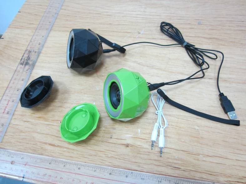
L5CR088G2
Jan 12, 2014Stereo Diamond Bluetooth Speaker/Stereo Powerball
Equipment Class
DSS - Part 15 Spread Spectrum Transmitter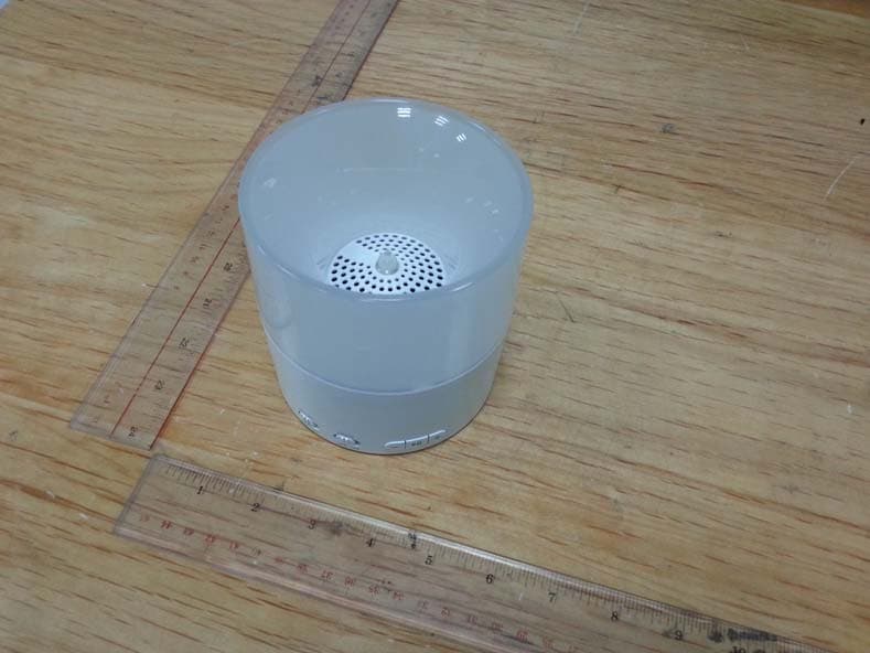
L5CR094G0
Nov 19, 2013Bluetooth Candle Light Speaker
Equipment Class
DSS - Part 15 Spread Spectrum TransmitterL5CR091GT
Sep 17, 2013BONE BLUETOOTH SPEAKER
Equipment Class
DSS - Part 15 Spread Spectrum TransmitterL5CR092GT
Sep 17, 2013X-CONCEPT BLUETOOTH SPEAKER
Equipment Class
DSS - Part 15 Spread Spectrum TransmitterL5CR080GT
Sep 17, 2013Candle Bluetooth Speaker
Equipment Class
DSS - Part 15 Spread Spectrum Transmitter