L5CW174TX-0RAIN GAUGE TRANSMITTER
Ansen Electronics Co
Click to zoom
Application Details
- Equipment Class
- DSC - Part 15 Security/Remote Control Transmitter
- Date of Grant
- Mar 21, 2010
- Application Purpose
- Original Equipment
- Date of Application
- Mar 17, 2010
- Equipment Note
- RAIN GAUGE TRANSMITTER
- Frequency Range
- 433.92000000 - 433.92000000
- Company
- Ansen Electronics Co
- Country
- Hong Kong
Documents & Files
Document Text
Text extracted from the exhibit documents filed with the FCC. Open a document above to read the original.
Users Manual
Personal Weather Station with Wireless Sensors for Temperature & Humidity/Wind Speed/Rain Model # 47009 Thank you for purchasing this Celestron personal weather station. Please read the instructions prior to using it and we hope you will have many years of pleasure with it. Insert the base to the bottom of the Receiver by pushing it in until it clicks. The correct position is shown in the images below. If you are going to mount the Receiver on a wall (or other level surface), remove the base after set up and see the “Placement” on the last page. You will need the following tools and supplies to mount the Anemometer and Rain Gauges --- small Phillips screwdriver, hex key – 5mm (3/16”), drill, level, pencil and mast. Set Up Power for the Receiver Open the battery compartment door on the rear of the Receiver (located in top center of image on the left). Then insert six AA batteries (user supplied) with polarity as indicated in the battery compartment (see image on the right). After installation, put the battery compartment door back on. For optimum performance, please place the Receiver away from metal and other sources of interference such as mobile phones, TVs, computers, appliances, etc. If the Receiver stops showing the display or dims, replace the batteries. ENGLISH 2 Set Up the Power, Installation & Make Settings for the Anemometer (Wind Gauge) and Wireless Remote Sensor Installation/Mounting--the first step is to select the location for the Anemometer that is outdoor and not blocked on the top or sides so wind can freely reach it. The distance can be from 328ft (100m) to the Receiver or closer in an open area (the closer the better for transmission reception). The best location is usually on a mast on a roof or other high open position. The Wireless Sensor is built into the Anemometer. Before mounting the Anemometer it is best to perform a transmission test where you install the batteries (new ones) in the Anemometer (see section below) to make sure all is ok and save a lot of time if you have to relocate the Anemometer. Place the Anemometer horizontally in your selected outdoor location and install the batteries. Press and hold the “CHANNEL/SEARCH” button for a few seconds and you will see wind direction, temperature, and humidity icons flash on the display as the Receiver is now searching for remote sensors. If the readings for the outdoor information are shown within ten minutes, the transmission is successful and you can go ahead with the mounting. If the readings are not shown after ten minutes, then relocate the place you want to mount the Anemometer closer to the Receiver and remove the batteries and try the procedure again. Remove the batteries from the Anemometer prior to mounting and calibration. Remove the four small screws (shown in above image) from the door of the Anemometer with a small screwdriver. Insert two AA batteries (user supplied) as indicated in the sensor (see right image above). Replace the door of the Anemometer by installing the four small screws to hold it in place. To mount the Anemometer, you need a mast (user supplied) about 1 to 1.25” (2.54 to 3.1cm) in diameter and hardware to mount permanently in the location where you want to mount the Anemometer – see drawing below. Note that if you have an existing mast for mounting an antenna or similar device, you can mount the Anemometer on it. You should mount and ground a mast as directed in the instructions provided with the mast. If you do not have a mast, you can purchase them at aerial or antenna suppliers. Place the U-shaped metal plates around the mast. Insert the four hex screws through the holes of the U-shaped plates and the holes on the Anemometer mounting bracket. The wind vane is to be above the metal bar of the Anemometer when it is in the horizontal position per the diagram below. Tighten the hex nut onto the hex screws. MAST NORTH MAST 3 Calibrating & Installing the Batteries of the Anemometer After mounting the Anemometer, you need to calibrate the wind direction so that the Anemometer properly measures the wind direction and transmits this information to the Receiver. Be sure the batteries have been removed from the Anemometer before the calibration. You will have to recalibrate the Anemometer whenever you replace the batteries. Use the compass on the Anemometer and turn the wind vane so it is pointing due north (see drawing). Hold the wind vane pointing due north and install the batteries. The red LED above the battery door will flash a few times right after battery installation. Be sure the vane is pointing due north at the moment when the red LED flashes and then the calibration is completed. Replace the battery door. Press and hold the “CHANNEL/SEARCH” button a few seconds and the Channel 1 readings will appear within 10 minutes if the wireless sensor transmission is successful. Set Up the Power and Installation of the Rain Gauge Choose a mounting location for the Rain Gauge that is a flat and level surface 164ft (50m) or closer in an open area from the Receiver where data can be transmitted easily. The Rain Gauge should not be blocked on the top or sides so that rain can freely reach the gauge (do not put under an overhang or too close to a building or fence). Also, do not mount too close to the ground or to trees or plants. To install the batteries in the Rain Gauge, turn it upside down (image below). Then, at the same time push the two clips (inside of the two large holes at the ends) inward and lift off the cover and battery compartment. Now turn the removed part upside down (image to the right) and pull out on the two clips of the battery cover. Insert two AA batteries (user supplied) per the polarity markings on the battery compartment. Then, replace the battery cover. Finally, replace the battery compartment and cover into the outer housing by aligning with the clips and then pushing down on the cover over the clips until they are secure. Push and hold the “CHANNEL/SEARCH” button …
Text truncated - open the document above for the full version.
Cover Letter(s)
AGENCY AUTHORIZATION LETTER FCC ID: L5CW174TX-0 Date: Mar 12, 2010 To whom it may concern: We, the undersigned, hereby authorize SHENZHEN HUATONGWEI INTERNATIONAL INSPECTION CO., LTD of China to act on our behalf, as our agent in the following matters related to the FCC approval of our products: report submittal, related correspondence, the signing of all documents relating to these matters, and any other lawful activity necessary to obtain such certification, Any act carried out by SHENZHEN HUATONGWEI INTERNATIONAL INSPECTION CO., LTD within the scope of this authorization shall have the same effects as our own. This authorization shall expire 6 months from original date. If you have any questions regarding the authorization, please don’t hesitate to contact us.
External Photos
V1.0 Page 23 of 25 Report No.: WE10030011 FCC ID: L5CW174TX-0 Shenzhen Huatongwei International Inspection Co., Ltd External Photos V1.0 Page 24 of 25 Report No.: WE10030011 FCC ID: L5CW174TX-0 Shenzhen Huatongwei International Inspection Co., Ltd
Internal Photos
V1.0 Page 25 of 25 Report No.: WE10030011 FCC ID: L5CW174TX-0 Shenzhen Huatongwei International Inspection Co., Ltd Internal Photos
Test Report
TEST REPORT FCC Part 15 Subpart C FCC ID .............................................: L5CW174TX-0 Report Reference No......................: WE10030011 Compiled by ( position+printed name+signature)..: File administrators Wenliang Li Supervised by ( position+printed name+signature)..: Test Engineer Cary Li Approved by ( position+printed name+signature)..: Manager Jimmy Li Date of issue.....................................: Jun 15, 2009 Testing Laboratory Name..............: Shenzhen Huatongwei International Inspection Co., Ltd Address.............................................: Keji Nan No.12 Road, Hi-tech Park, Shenzhen, China Applicant’s name............................: Ansen Electronics Co Address.............................................: Rm 78,2/F,Sino Industrial Plaza,9 Kai Cheung Rd,Kowloon Bay Manufacturer’s name.....................: Ansen Electronics Company Address.............................................: Chen Tung Industrial Zone,Ning Tau Administrative District,Qiao Tau Zhen,Dongguan,Guangdong Test specification: Standard ...........................................: FCC Part 15 Subpart C 2008 – Intentional Radiators ANSI C63.4 - 2003 TRF Originator ..................................: Shenzhen Huatongwei International Inspection CO., Ltd Master TRF.......................................: Dated 2006-06 Shenzhen Huatongwei International Inspection Co., Ltd. All rights reserved. This publication may be reproduced in whole or in part for non-commercial purposes as long as the Shenzhen Huatongwei International Inspection Co., Ltd is acknowledged as copyright owner and source of the material. Shenzhen Huatongwei International Inspection Co., Ltd takes no responsibility for and will not assume liability for damages resulting from the reader’s interpretation of the reproduced material due to its placement and context. Equipment Under Test .................. : Rain Gauge Transmitter Trade Mark .......................................: / Model/Type reference.......................: W174-0 Listed Models ..................................: / Result...............................................: Complied V1.0 Page 2 of 25 Report No.: WE10030011 FCC ID: L5CW174TX-0 Shenzhen Huatongwei International Inspection Co., Ltd T E S T R E P O R T Test Report No. : WE10030011 Mar 15, 2010 Date of issue Equipment under Test : Rain Gauge Transmitter Model /Type : W174-0 Listed Models : / Applicant : Ansen Electronics Co Address : Rm 78,2/F,Sino Industrial Plaza,9 Kai Cheung Rd,Kowloon Bay Manufacturer : Ansen Electronics Company Address : Chen Tung Industrial Zone,Ning Tau Administrative District,Qiao Tau Zhen,Dongguan,Guangdong Test Result Complied The test report merely corresponds to the test sample. It is not permitted to copy extracts of these test result without the written permission of the test laboratory. V1.0 Page 3 of 25 Report No.: WE10030011 FCC ID: L5CW174TX-0 Shenzhen Huatongwei International Inspection Co., Ltd Contents 1. TEST STANDARDS AND RESULT SUMMARY ................................ 4 2. EUT SUMMARY....................................................................... 5 2.1. General Remarks 5 2.2. Equipment Under Test Power Supply 5 2.3. Short description of the Equipment under Test (EUT) 5 2.4. EUT operation mode 5 2.5. Configuration of Tested System 6 2.6. Related Submittal(s) / Grant (s) 6 2.7. Modifications 6 3. TEST ENVIRONMENT............................................................... 7 3.1. Address of the test laboratory 7 3.2. Test Facility 7 3.3. Environmental conditions 8 3.4. Statement of the measurement uncertainty 8 3.5. Equipments Used during the Test 9 4. TEST CONDITIONS AND RESULTS ............................................ 10 4.1. Radiated Emission 10 4.2. Deactivation Time 17 4.3. 20dB Bandwidth 19 4.4. Antenna Requirement 21 5. TEST SETUP PHOTOS OF THE EUT .......................................... 22 6. EXTERNAL AND INTERNAL PHOTOS OF THE EUT ....................... 23 V1.0 Page 4 of 25 Report No.: WE10030011 FCC ID: L5CW174TX-0 Shenzhen Huatongwei International Inspection Co., Ltd 1. TEST STANDARDS AND RESULT SUMMARY The tests were performed according to following standards: FCC Rules Part 15 Subpart C (2008) - Intentional Radiators ANSI C63.4 (2003) – American National Standard for Methods of Measurement of Radio-Noise Emissions from Low-Voltage Electrical and Electronic Equipment in the Range of 9kHz to 40GHz SUMMARY OF STANDARDS AND RUSELT No. Test Item Test Standards and Procedure Result 1 Radiated Emission FCC Subpart 15C§15.231(e) ANSI C63.4-2003 section 13.1.4 PASS 2 Deactivation Time FCC Subpart 15C§15.231(e) PASS 3 20dB Bandwidth FCC Subpart 15C§15.231(c) ANSI C63.4-2003 section 13.1.7 PASS 4 Antenna Requirement FCC Subpart 15C§15.203 PASS NOTE: 1), The detailed test rusult please see section 4. 2), The test report merely corresponds to the test sample. 3), It is not permitted to copy extracts of these test result without the written permission of the test laboratory. V1.0 Page 5 of 25 Report No.: WE10030011 FCC ID: L5CW174TX-0 Shenzhen Huatongwei International Inspection Co., Ltd 2. EUT SUMMARY 2.1. General Remarks Date of receipt of test sample : Mar 10, 2010 Testing commenced on : Mar 10, 2010 Testing concluded on : Mar 15, 2010 2.2. Equipment Under Test Power Supply Power supply voltage : 120V / 60 Hz 115V / 60Hz 12 V DC 24 V DC Other (specified in blank below) DC 3V (2x1.5V AA Battery) 2.3. Short description of the Equipment under Test (EUT) Product Name : Rain Gauge Transmitter Model Number : W174-0 Operation Frequency : 433.92MHz Modulation Technology : ASK Transmitter Type : Periodic Transmitter Sample Type : Prototype For more details, refer to the user’s manual. 2.4. EUT operation mode The EUT has been tested under typical operating mode. Test Item Test Mode Note Radiated Emission Tx mode(433.92MHz) X-axis Deactivation Time Tx mode(433.92MHz) / 20dB Bandwidth Tx mode(433.92MHz) / Duty cycle Tx mode(433.92MHz) / V1.0 Page…
Text truncated - open the document above for the full version.
Contact Information
Applicant
Alvin Luo(QE Manager)
Test Firm
Shenzhen Huatongwei International Insp. Co., LtdMoffy Yu
Technical Specifications
| # | Rule Parts | Frequency Range | Power Output |
|---|---|---|---|
| 1 | 15.231 | 433.92 MHz - 433.92 MHz | 71.8 W |
Other Applications from Ansen Electronics Co
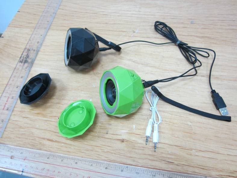
L5CR088G2
Jan 12, 2014Stereo Diamond Bluetooth Speaker/Stereo Powerball
Equipment Class
DSS - Part 15 Spread Spectrum Transmitter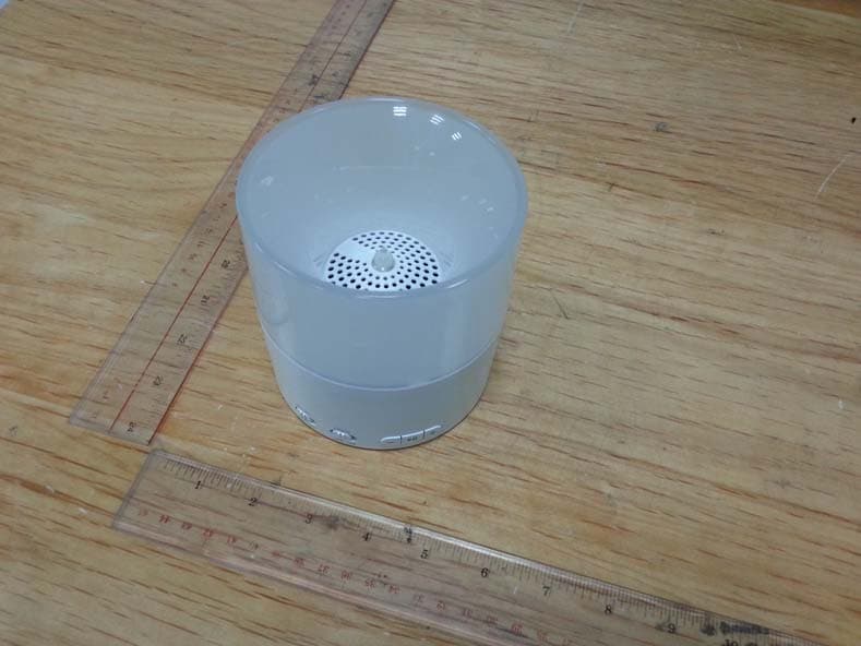
L5CR094G0
Nov 19, 2013Bluetooth Candle Light Speaker
Equipment Class
DSS - Part 15 Spread Spectrum TransmitterL5CR091GT
Sep 17, 2013BONE BLUETOOTH SPEAKER
Equipment Class
DSS - Part 15 Spread Spectrum TransmitterL5CR092GT
Sep 17, 2013X-CONCEPT BLUETOOTH SPEAKER
Equipment Class
DSS - Part 15 Spread Spectrum TransmitterL5CR080GT
Sep 17, 2013Candle Bluetooth Speaker
Equipment Class
DSS - Part 15 Spread Spectrum Transmitter