LDK102039
Cisco Systems Inc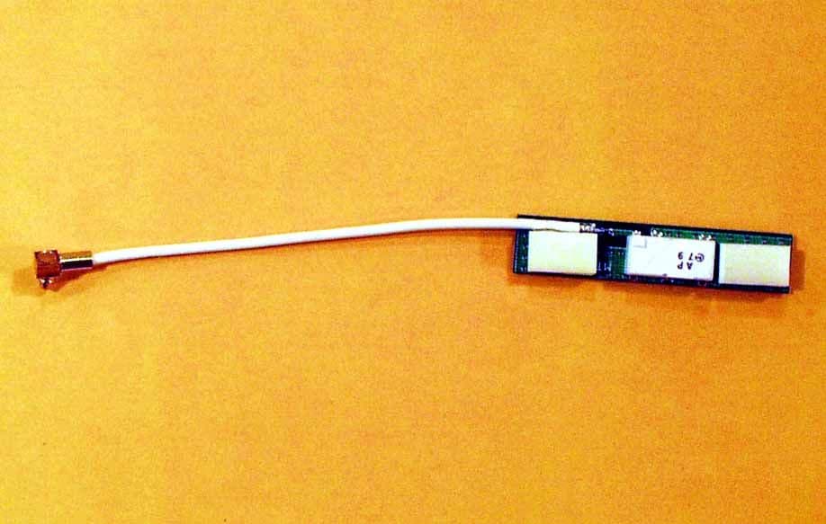
Click to zoom
Application Details
- Equipment Class
- DSS - Part 15 Spread Spectrum Transmitter
- Date of Grant
- Jun 13, 2000
- Application Purpose
- Original Equipment
- Date of Application
- Mar 13, 2000
- Frequency Range
- 2412.00000000 - 2465.00000000
- Company
- Cisco Systems Inc
- Country
- United States
Documents & Files
Document Text
Text extracted from the exhibit documents filed with the FCC. Open a document above to read the original.
Users Manual
Test report #20000282FFCC 15.231 for MI-4800BFCC ID: LDK102039 Tested February 2, 2000 AHD EMC Lab, 92723 M152, Dowagiac, MI 49047, (616) 424-701491442 Exhibit N: Page 1 of 4 EXHIBIT N: M ANUAL A portion of the proposed Manual for the OEM customer is reproduced here. CHAPTER 7 A OEM R ADIO A PPROVAL I NFORMATION This chapter contains information about the approvals, regulations, labeling requirements and configuration of the MI4800 radio module for operation in various countries. Approvals Safety The MI4800 is designed to meet the requirements of UL, CSA, VCCI and is compliant to the European Low Voltage Directives. However, the OEM is responsible for the individual safety agency approval of the entire OEM product. If necessary, Aironet will furnish any required information directly to the agency for the approval. The MI4800 is compliant to ANSI C95.1 1991, FCC OET-65 and Industry Canada’s RSS-102 requirements for Safety Levels with Respect to Human Exposure to Radiated Frequency Electromagnetic Fields, 3kHz to 300GHz. FCC Approvals (US and Territories) The MI4800 has full modular approval from the FCC under 15.247 of the FCC rules with a 2.2dBi dipole antenna or equivalent. This certification applies to operation in the United States and its territories (Guam, American Samoa, Puerto Rico, and US Virgin Islands). The FCC ID for the MI4800 is LDK102039. The OEM is responsible for the overall compliance of the OEM product to the FCC rules as stated in CFR 47 Part 15 (1998). The OEM is responsible for manufacturing, installing, and operating this equipment in compliance to CFR 47 Parts 2 and 15. Aironet's FCC approval covers the radio and approved antennas only. The use of antennas not approved by the FCC for use with the Aironet radio is in violation of the FCC rules. Using FCC approved antennas If the OEM is using an Aironet FCC approved antenna, the OEM will be required to test the entire OEM product to Part 15 Subpart B for unintentional radiators. No additional FCC application or paperwork will be required concerning the radio itself. The OEM is responsible for the product meeting all applicable FCC standards. Using third-party ante nnas If the OEM is using a third-party antenna, Aironet Engineering will review the antenna specifications to determine if it will be covered under the family group of approved antennas. If the antenna falls under the family approval, then Aironet Engineering will issue a letter stating that the antenna is covered under the family approval and then Aironet will add the information to our files. If the antenna does not fall under the family approval, a FCC Class II Permissive Change or a FCC re-certification is required before it can be used w ith our radio. The Class II Permissive Change must be done through Aironet Engineering or our authorized agent. Contact your sales agent for further information. The FCC re-certification process is the responsibility of the OEM with the support of Aironet Engineering. Aironet will provide any necessary non-confidential information to the test lab and any confidential information directly to the FCC. Test report #20000282FFCC 15.231 for MI-4800BFCC ID: LDK102039 Tested February 2, 2000 AHD EMC Lab, 92723 M152, Dowagiac, MI 49047, (616) 424-701491442 Exhibit N: Page 2 of 4 DOC Approvals (Canada) The MI4800 is certified for use in accordance with RSS-210 and RSS-139-1. Spread spectrum systems in the 2.4GHz range operating completely indoors or outdoors above 2450MHz do not require licensing. Those systems operating partially or completely outdoors below 2450MHz may require a license to operate. Additional information can be found in the CPC-2-0-01 Guidelines for Submission of Applications and the IC 2365BB Application for License to Install and Operate a Radio Transmitter. The Canadian Radio Approval number for the MI4800 is still pending as of the publication date of this document. If the OEM wishes to use an Aironet approved radio and antenna combination, the OEM will be required to have the entire OEM product tested, but no formal application for approval is necessary except "multi-listing" of the radio for use in the OEM product. If product qualification (EMC approval) is required, the OEM will submit his application to the DOC and reference the appropriate Aironet file. Aironet will interface with the Canadian authorities to update the files with the proper information for certification. The OEM has the option of submitting his own application to the DOC in which case Aironet will provide information on the radio and antenna to the DOC. Any future changes to the OEM product can be done without contacting Aironet since the product registration will be in the OEM name. If the OEM is using a third-party antenna, the OEM will be required to file the test report and application with the DOC on the OEM product, and Aironet will send any necessary confidential information directly to the Canadian DOC. ETSI Approvals (Europe) Ge ne ral Information Based on the recent changes in the interpretation of the certification of radio modules by the European Union, the MI4800 will now have modular approval. The maximum power rating for ETSI is 100mW EIRP. Depending on the product and antenna used, the installation of the radio may or may not require the OEM to obtain a separate radio type approval certificate for the OEM product. It is the OEM's responsibility to contact the European local authorities, Competent Body or Notified Body test lab to determine what applicable standards need to be applied for the product. The OEM can obtain the appropriate approval numbers and copy of certifications of the radio from their Aironet Sales agent. The OEM will be required to test the OEM product with the radio installed to the requirements of EN 55022, EN 50082-1 and the Low Voltage Directive. The MI4800 is designed to meet EN 55022 Class B levels. However, any additional shielding or filtering required to bring the overall product into compli…
Text truncated - open the document above for the full version.
Cover Letter(s)
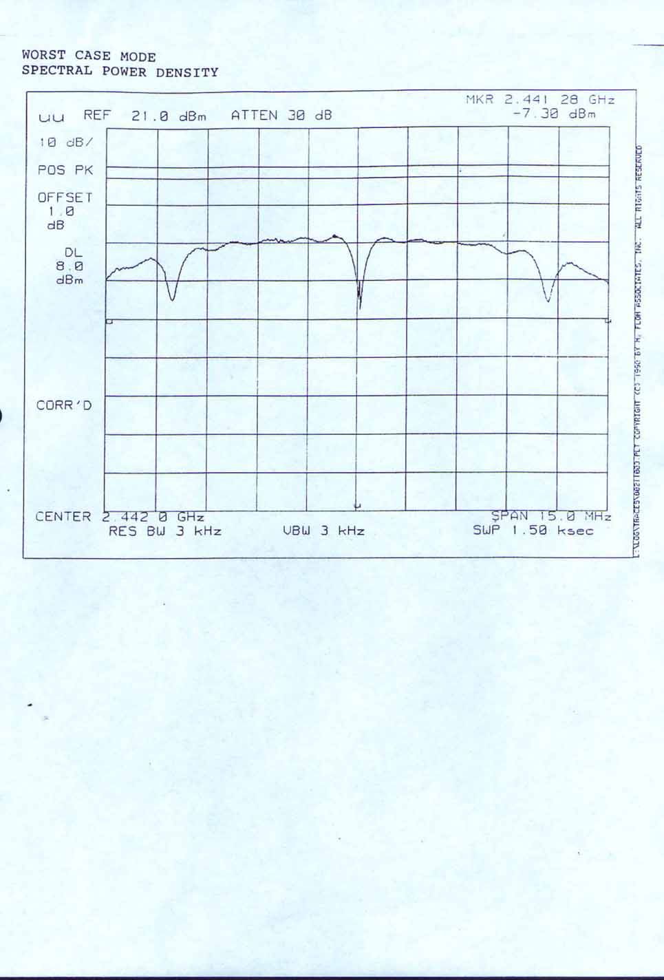
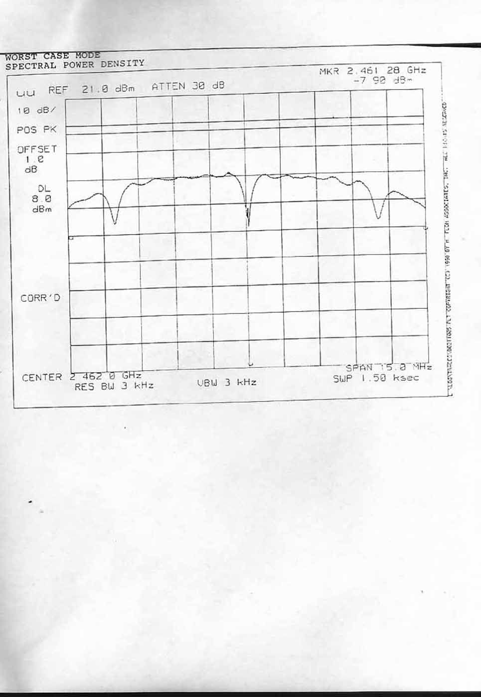
AHD EMC Lab, 92723 M152, Dowagiac, MI 49047, (616) 424-701491344 Exhibit A: Page 1 of 2 NVLAP ACCREDITED NARTE Certified Engineer Professional Engineer Federal communications CommissionMarch 10, 2000 Equipment Approval Services, P.O. Box 358315 Pittsburgh, PA 15251-5315 Attention: Authorization & Evaluation Division Re: Application for Certification of Aironet Wireless Communications, Inc. under 47CFR 15.247. FCC ID: LDK102039 Gentlemen: On behalf of the applicant, Aironet Wireless Communications, Inc., please find attached the submittal materials for certification of the Aironet 2.4GHz Direct Sequence Spread Spectrum transmitter / receiver. Pursuant to 47CRF 0.459, Aironet Wireless Communications requests that these listed exhibits be held confidential. Exhibit DProcessing Gain Information/Calculations Exhibit GTheory/Description of Operation, Exhibit H:Circuit Block Diagrams Exhibit I:Schematics Exhibit J:Tuneup Information Aironet Wireless Communications has invested considerable resources into developing this DSSS. Having the listed exhibits available to ‘competition’ would negate the advantage achieved in developing this product. Since the DSSS devices are a major product line for Aironet, not protecting the details of the design will result in a financial hardship for the company. The complete List of the Exhibits in this submittal package appears on Page 2 of this cover letter. Your prompt consideration of this application for product certification will be greatly appreciated. Should you have any questions regarding the content of this report, kindly contact me. Sincerely, Ted Chaffee, Technical Lab Manager Narte Certified Engineer, #EMC-002025-NE tel/fax: 616. 424.7014 email: [email protected], or [email protected] Test report #20000282FFCC 15.247 for MI-4800BFCC ID: LDK102039 Tested February 2, 2000 AHD EMC Lab, 92723 M152, Dowagiac, MI 49047, (616) 424-701491344 Exhibit A: Page 2 of 2 Table of Contents Form 731, form 159 with payment EXHIBIT A: Cover Letter / Table of ContentsTotal Pages 2 EXHIBIT B: Statements of Attestation [2.911(d)]Total Pages 3 Attesting to Accuracy of DataExhibit B, File “EXB_p1DataAttst.jpg” Public Notice 22504 Exhibit B, File “EXB_p1DataAttst.jpg” Power of Attorney Exhibit B, File “EXB_p2PowrOAttrny.pdf” AHD AccreditationExhibit B, File “EXB_p3NV:APCert.jpg” EXHIBIT C: Description of Product [2.1033(b)] Total Pages 1 EXHIBIT D: Processing Gain Information/Calculations [15.247(e)] Total Pages 2 EXHIBIT E: Product photos - [2.1033(b7)] Five photosTotal Pages 4 EXHIBIT F: ID Label / Location [2.925,2.926,2.1033(b2,7)] Total Pages 1 EXHIBIT G: Description of Operation [2.1033(b4,5)] Total Pages 1 EXHIBIT H: Circuit Block Diagram [2.1033(b5)] Total Pages 1 EXHIBIT I:Schematics [2.1033(b5)] Total Pages 1 EXHIBIT J: Tune-up Information [2.1033(b5] Total Pages 2 EXHIBIT K: Report of Measurements [2.1033(b6)] Total Pages 33 Detailed Table of ContentsExhibit K, Page 2 Manufacturer/Applicant [2.1033(b1)Exhibit K, Page 4 Measurement/Test Facility & EquipmentExhibit K, Page 4 Configuration/Setup [2.1033(b8)]Exhibit K, Page 5 Summary of ResultsExhibit K, Page 7 Test Standards / Methods Used [2.1033(b6)] Exhibit K, Page 8 Test Methodology [2.1033(b6)]Exhibit K, Page 8 Test Data [2.1033(b6)]Exhibit K, Page 10 Spectral Power Density [15.247(d)] Exhibit K, Page 10 Minimum 6dB Bandwidth[15.247(a2) Exhibit K, Page 12 Peak Power Output [15.247(b1)]Exhibit K, Page 14 Band Edge emissions [15.247(c)]Exhibit K, Page 15 Transmitter Harmonics[15.205,209)] Exhibit K, Page 30 Spurious Emissions[15.33(b)]Exhibit K, Page 32 EXHIBIT L: Setup photos [2.1033(b8)] Eight photosTotal Pages 5 EXHIBIT M: RF Exposure Information [15.247(b4)]Total Pages 1 EXHIBIT N: User’s Manual Total Pages 4
Cover Letter(s)
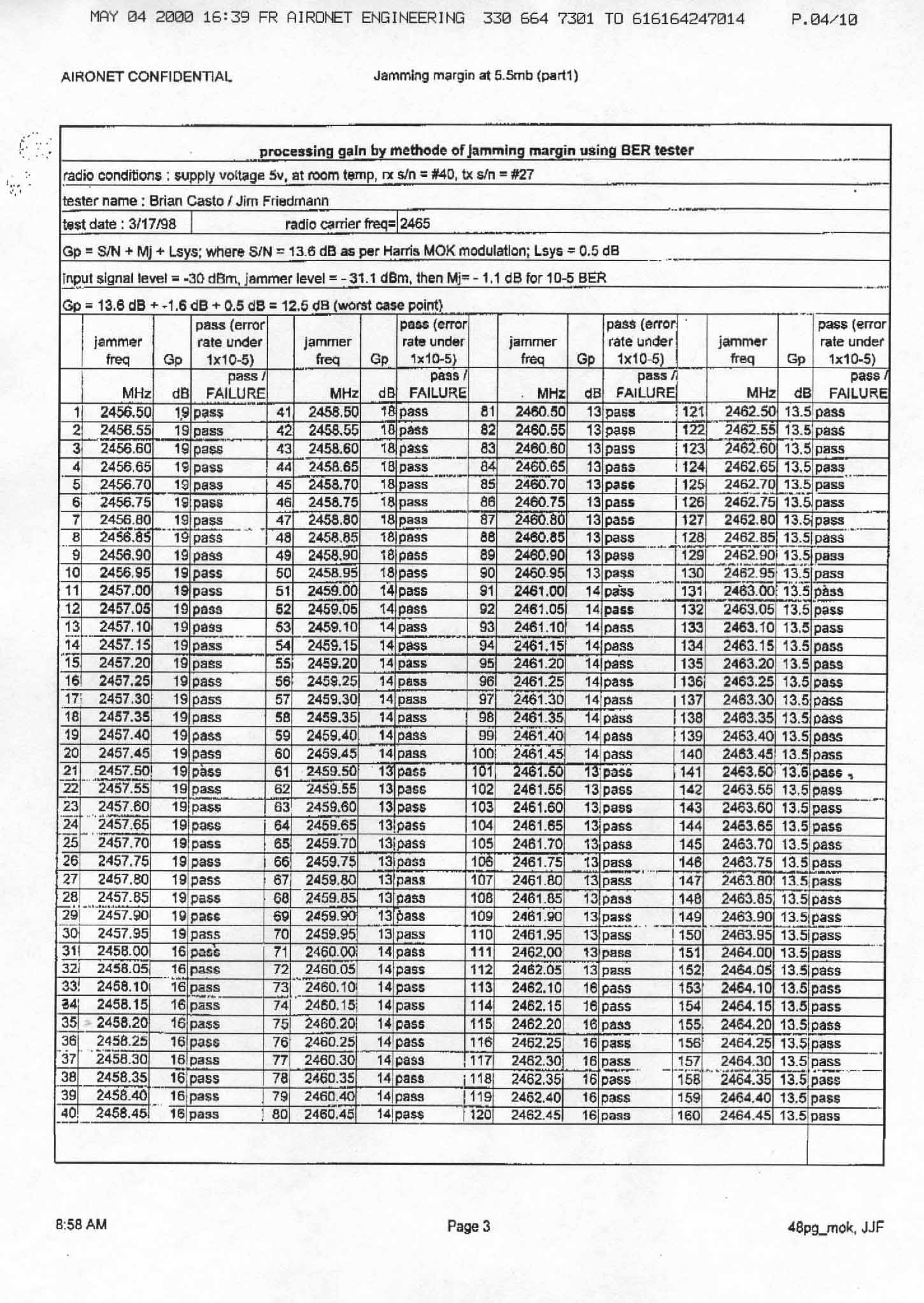
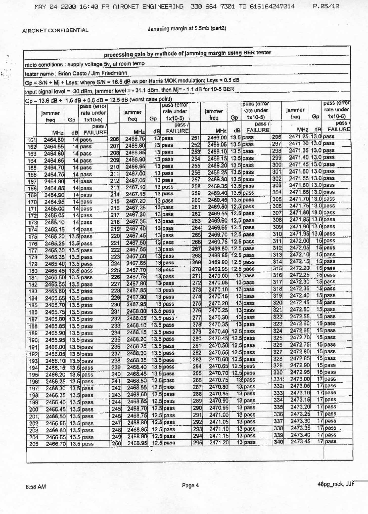
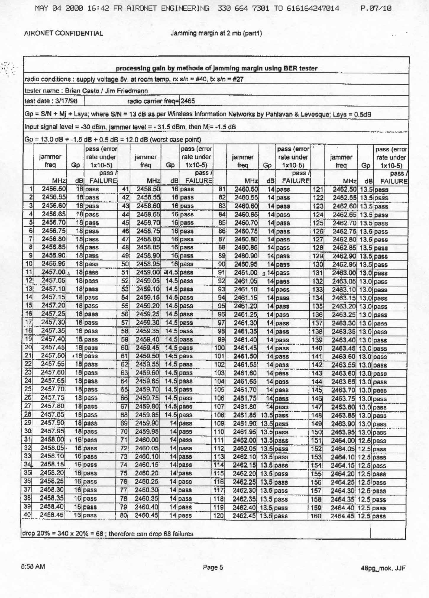
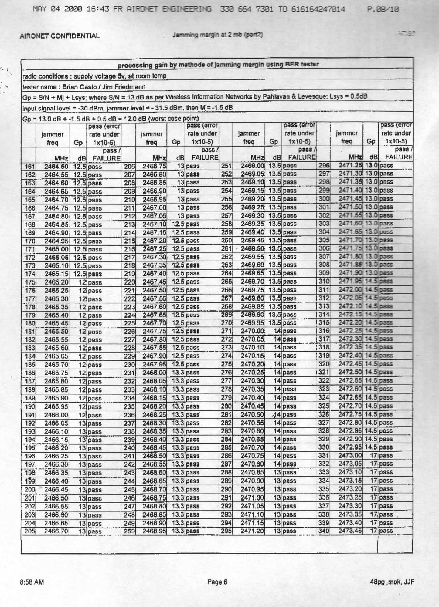
AHD EMC Lab, 92723 M152, Dowagiac, MI 49047, (616) 424-701499060 Exhibit A: Page 1 of 2 NVLAP ACCREDITED NARTE Certified Engineer Professional Engineer Federal communications CommissionMay 3, 2000 Equipment Approval Services, P.O. Box 358315 Pittsburgh, PA 15251-5315 Attention: Authorization & Evaluation Division Re: Application for Certification of Aironet Wireless Communications, Inc. under 47CFR 15.247. FCC ID: LDK102039 Gentlemen: On behalf of the applicant, Aironet Wireless Communications, Inc., please find attached the submittal materials for certification of the Aironet 2.4GHz Direct Sequence Spread Spectrum transmitter / receiver. Pursuant to 47CRF 0.459, Aironet Wireless Communications requests that these listed exhibits be held confidential. Exhibit GTheory/Description of Operation, Exhibit H:Circuit Block Diagrams Exhibit I:Schematics Exhibit J:Tuneup Information Aironet Wireless Communications has invested considerable resources into developing this DSSS. Having the listed exhibits available to ‘competition’ would negate the advantage achieved in developing this product. Since the DSSS devices are a major product line for Aironet, not protecting the details of the design will result in a financial hardship for the company. The complete List of the Exhibits in this submittal package appears on Page 2 of this cover letter. Your prompt consideration of this application for product certification will be greatly appreciated. Should you have any questions regarding the content of this report, kindly contact me. Sincerely, Ted Chaffee, Technical Lab Manager Narte Certified Engineer, #EMC-002025-NE tel/fax: 616. 424.7014 email: [email protected], or [email protected] Test report #20000282FFCC 15.247 for MI-4800BFCC ID: LDK102039 Tested February 2, 2000 AHD EMC Lab, 92723 M152, Dowagiac, MI 49047, (616) 424-701499060 Exhibit A: Page 2 of 2 Table of Contents Form 731, form 159 with payment EXHIBIT A: Cover Letter / Table of ContentsTotal Pages 2 EXHIBIT B: Statements of Attestation [2.911(d)]Total Pages 3 Attesting to Accuracy of DataExhibit B, File “EXB_p1DataAttst.jpg” Public Notice 22504 Exhibit B, File “EXB_p1DataAttst.jpg” Power of Attorney Exhibit B, File “EXB_p2PowrOAttrny.pdf” AHD AccreditationExhibit B, File “EXB_p3NV:APCert.jpg” EXHIBIT C: Description of Product [2.1033(b)] Total Pages 1 EXHIBIT D: Processing Gain Information/Calculations [15.247(e)] Total Pages 2 Processing Gain Jamming Test DataTotal Pages 8 EXHIBIT E: Product photos - [2.1033(b7)] Five photosTotal Pages 4 EXHIBIT F: ID Label / Location [2.925,2.926,2.1033(b2,7)] Total Pages 1 EXHIBIT G: Description of Operation [2.1033(b4,5)] Total Pages 1 EXHIBIT H: Circuit Block Diagram [2.1033(b5)] Total Pages 1 EXHIBIT I:Schematics [2.1033(b5)] Total Pages 1 EXHIBIT J: Tune-up Information [2.1033(b5] Total Pages 2 EXHIBIT K: Report of Measurements [2.1033(b6)] Total Pages 33 Detailed Table of ContentsExhibit K, Page 2 Manufacturer/Applicant [2.1033(b1)Exhibit K, Page 4 Measurement/Test Facility & EquipmentExhibit K, Page 4 Configuration/Setup [2.1033(b8)]Exhibit K, Page 5 Summary of ResultsExhibit K, Page 7 Test Standards / Methods Used [2.1033(b6)] Exhibit K, Page 8 Test Methodology [2.1033(b6)]Exhibit K, Page 8 Test Data [2.1033(b6)]Exhibit K, Page 10 Spectral Power Density [15.247(d)] Exhibit K, Page 10 Minimum 6dB Bandwidth[15.247(a2) Exhibit K, Page 12 Peak Power Output [15.247(b1)]Exhibit K, Page 14 Band Edge emissions [15.247(c)]Exhibit K, Page 15 Transmitter Harmonics[15.205,209)] Exhibit K, Page 30 Spurious Emissions[15.33(b)]Exhibit K, Page 32 EXHIBIT L: Setup photos [2.1033(b8)] Eight photosTotal Pages 5 EXHIBIT M: RF Exposure Information [15.247(b4)]Total Pages 2 EXHIBIT N: User’s Manual Total Pages 4
ID Label/Location Info
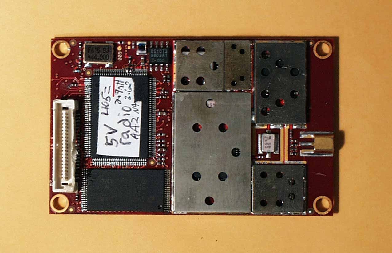
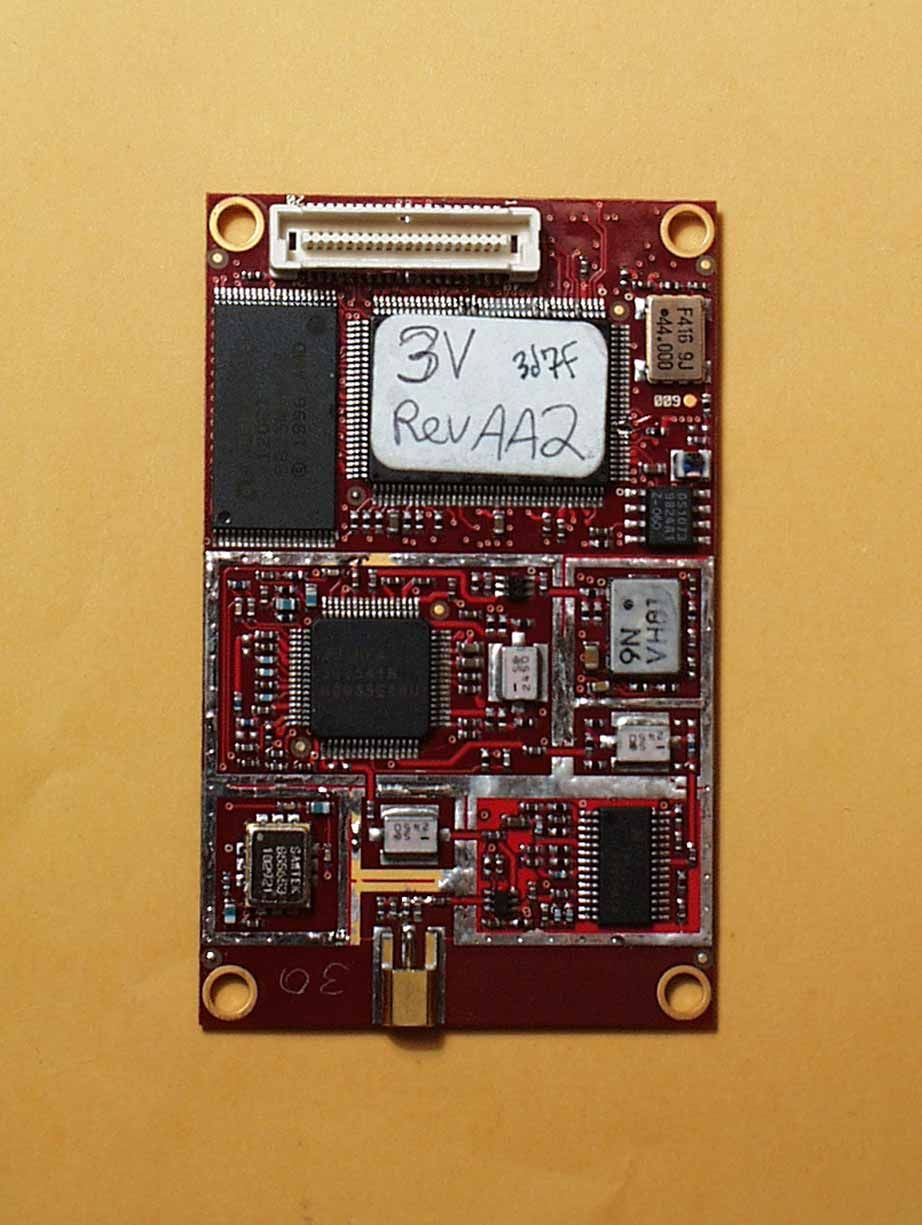
Test report #20000282FFCC 15.231 for MI-4800BFCC ID: LDK102039 Tested February 2, 2000 AHD EMC Lab, 92723 M152, Dowagiac, MI 49047, (616) 424-701492480 Exhibit F: Page 1 of 2 EXHIBIT F: E QUIPMENT L ABEL [2.925, 2.926, 2.1033( B 2,7), 15.19( A 3)] LABEL Example / Drawing Refer to file “EXF_Labelinfo.pdf” The FCC Identifier assigned to the MI-4800B is FCC ID: LDK102039. This number will be imprinted on the 1.500” x 0.812” white label. The label will be affixed to the product as described in the excerpt from the OEM customer manual reproduced here. OEM Labeling Requirements US and US Territories In accordance with FCC rules, the OEM product must have the radio approval number on the product label. This can be a second label added to the outside of the product. The label wording should be as follows: This product contains Airone t Radio Module FCC ID: LDK102039 Canada In accordance with Canadian DOC rules, the OEM product must have the radio approval number on the product label. This can be a second label added to the outside of the product. The label wording should be as follows: This product contains Airone t Radio Module Canada (pe nding) Europe In compliance with the European Telecommunication Standards and European Authorities, the OEM product must have the radio approval number on the product label. This can be a second label added to the outside of the product. The label wording should be as follows: This product contains Airone t Radio Module Place the appropriate country identification number and country symbols here Other Countries The product must be labeled in accordance with the requirements of the specific country.
ID Label/Location Info
Test report #20000282FFCC 15.231 for MI-4800BFCC ID: LDK102039 Tested February 2, 2000 AHD EMC Lab, 92723 M152, Dowagiac, MI 49047, (616) 424-701492483 Exhibit F: Page 1 of 2 EXHIBIT F: E QUIPMENT L ABEL [2.925, 2.926, 2.1033( B 2,7), 15.19( A 3)] LABEL Example / Drawing Refer to file “EXF_Labelinfo.pdf” The FCC Identifier assigned to the MI-4800B is FCC ID: LDK102039. This number will be imprinted on the 1.500” x 0.812” white label. The label will be affixed to the product as described in the excerpt from the OEM customer manual reproduced here. OEM Labeling Requirements US and US Territories In accordance with FCC rules, the OEM product must have the radio approval number on the product label. This can be a second label added to the outside of the product. The label wording should be as follows: This product contains Airone t Radio Module FCC ID: LDK102039 Canada In accordance with Canadian DOC rules, the OEM product must have the radio approval number on the product label. This can be a second label added to the outside of the product. The label wording should be as follows: This product contains Airone t Radio Module Canada (pe nding) Europe In compliance with the European Telecommunication Standards and European Authorities, the OEM product must have the radio approval number on the product label. This can be a second label added to the outside of the product. The label wording should be as follows: This product contains Airone t Radio Module Place the appropriate country identification number and country symbols here Other Countries The product must be labeled in accordance with the requirements of the specific country.
ID Label/Location Info
! CISCO LABEL DEFINITION DOCUMENT NOTES: 1) LABEL STOCK REFERANCE: LBL- 2) MAIN LABEL SIZE REF: 3) AUXILIARY LABEL SIZE REF: 4) CORNER RADII REF: .062 ( NOT ACCURATELY SHOWN ABOVE) 5) BACKGROUND COLOR REF: WHITE 6) PRINT TYPE & COLOR: HELVETICA NORMAL/BLACK PART NAME: DRAWN BY: DATE: PART NUMBER: This product contains FCC ID: LDK102039 Canada:XXXXXXXXXXXX 550-004711 1.500 x .812 NA 550-005633 LABEL, LOGO/PRODUCT, MI341-3 DNJ03/28/00 AIR-MI341-3 REF. REVISION:A0 PN: 100-005619-001 2.4GHz DS 11Mbps |+ Cisco Systems, Inc. 170 West Tasman Drive San Jose, CA 95134-1706 USA Wireless LAN Module 550-005633
ID Label/Location Info
AHD EMC Lab, 92723 M152, Dowagiac, MI 49047, (616) 424-701499808 20000282 EMC Testing/Engineering Services S TATEMENT OF C OMPLIANCE FOR PRODUCT EMISSIONS R EGULATORY S TANDARD FCC Part 15, Subpart B FCC Part 15, Subpart B FCC Part 15, Subpart B FCC Part 15, Subpart B Digital Device, Class B Digital Device, Class B Digital Device, Class B Digital Device, Class B N AME OF E QUIPMENT 2.4GHz DSSS Transceiver Module 2.4GHz DSSS Transceiver Module 2.4GHz DSSS Transceiver Module 2.4GHz DSSS Transceiver Module M ODEL N UMBER ( S ) MI-4800B MI-4800B MI-4800B MI-4800B AIR-340-x AIR-340-xAIR-340-x AIR-340-x M ANUFACTURER CISCO SYSTEMS, Inc. / AIRONET CISCO SYSTEMS, Inc. / AIRONET CISCO SYSTEMS, Inc. / AIRONET CISCO SYSTEMS, Inc. / AIRONET 3875 Embassy Parkway, 3875 Embassy Parkway, 3875 Embassy Parkway, 3875 Embassy Parkway, Akron, OH 44333 Akron, OH 44333 Akron, OH 44333 Akron, OH 44333 T EST D ATE January 30-February 2, 2000 January 30-February 2, 2000 January 30-February 2, 2000 January 30-February 2, 2000 AHD R EPORT N UMBER 20000282F 20000282F 20000282F 20000282F According to testing performed at the AHD Open Area Test Site, the above-mentioned unit is in compliance with Class B limits defined in Part 15 of FCC Rules and Regulations. Compliance is demonstrated in the configuration and with the changes, if required, outlined in the product test report. It is the manufacturer's responsibility to assure that additional production units of this model are manufactured with identical electrical and mechanical components. As the responsible EMC Test Engineer, I hereby declare that the equipment, specified above, conforms to the Class B RFI Suppression Requirements of FCC Rules Part 15. Date : Ted Chaffee, NCE Test Engineer NVLAP Lab Code: 200129-0 AHD EMC Lab, 92723 M152, Dowagiac, MI 49047, (616) 424-701499808
ID Label/Location Info
Declaration of Conformity FCC Compliance Information Statement Cisco Model Number: AIR-MI340 2.4GHz DSSS Transceiver Module FCC Part 15 B Class B Tested by:AHD EMC Labs 92723 M-152 Dowagiac MI January 30- February 2, 2000 This device complies with part 15 of the FCC Rules. Operation is subject to the following two conditions: (1) This device may not cause harmful interference, and (2) this device must accept any interference received, including interference that may cause undesired operation. Manufacturer: Cisco Systems Inc 3875 Embassy Parkway Akron OH 44333
Operational Description
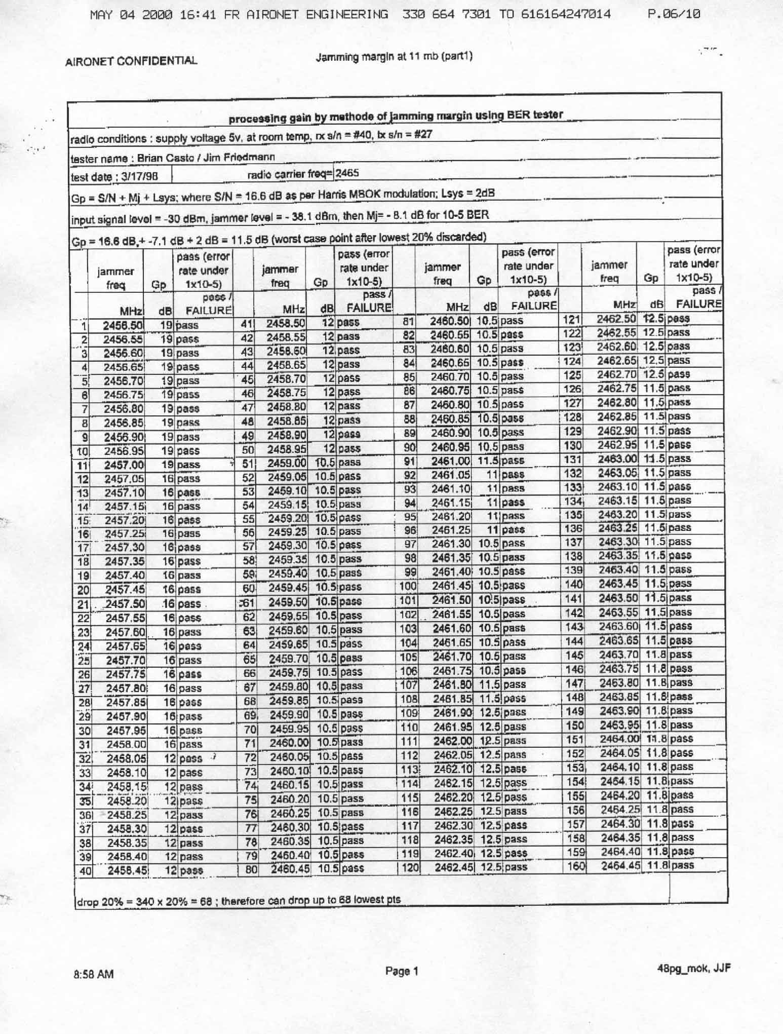
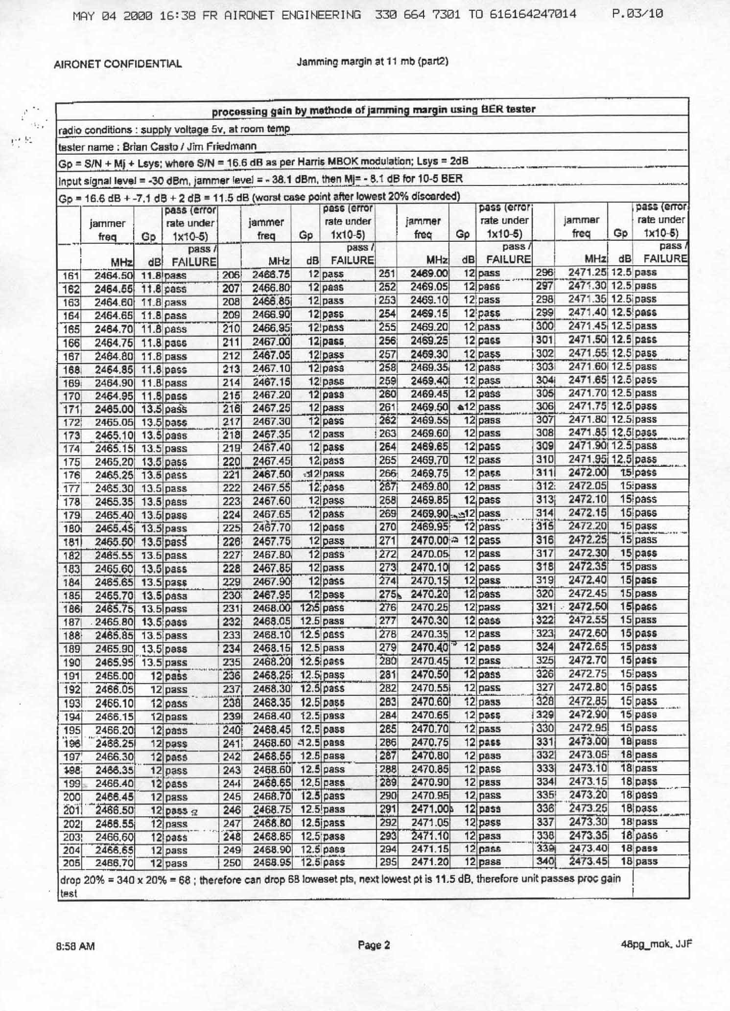
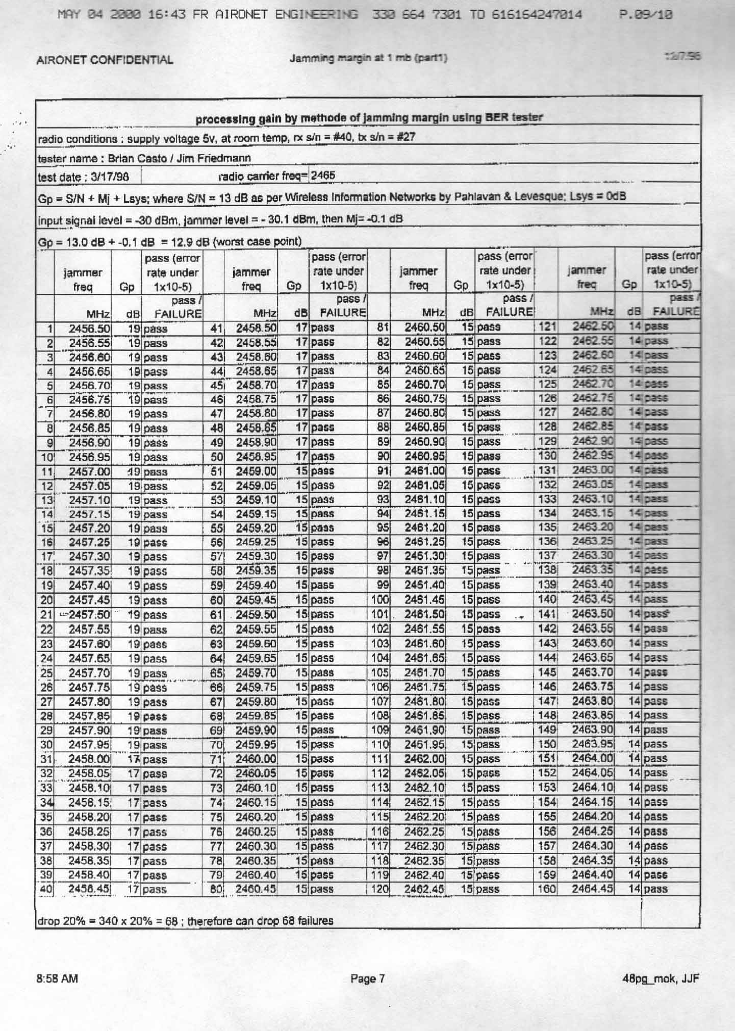
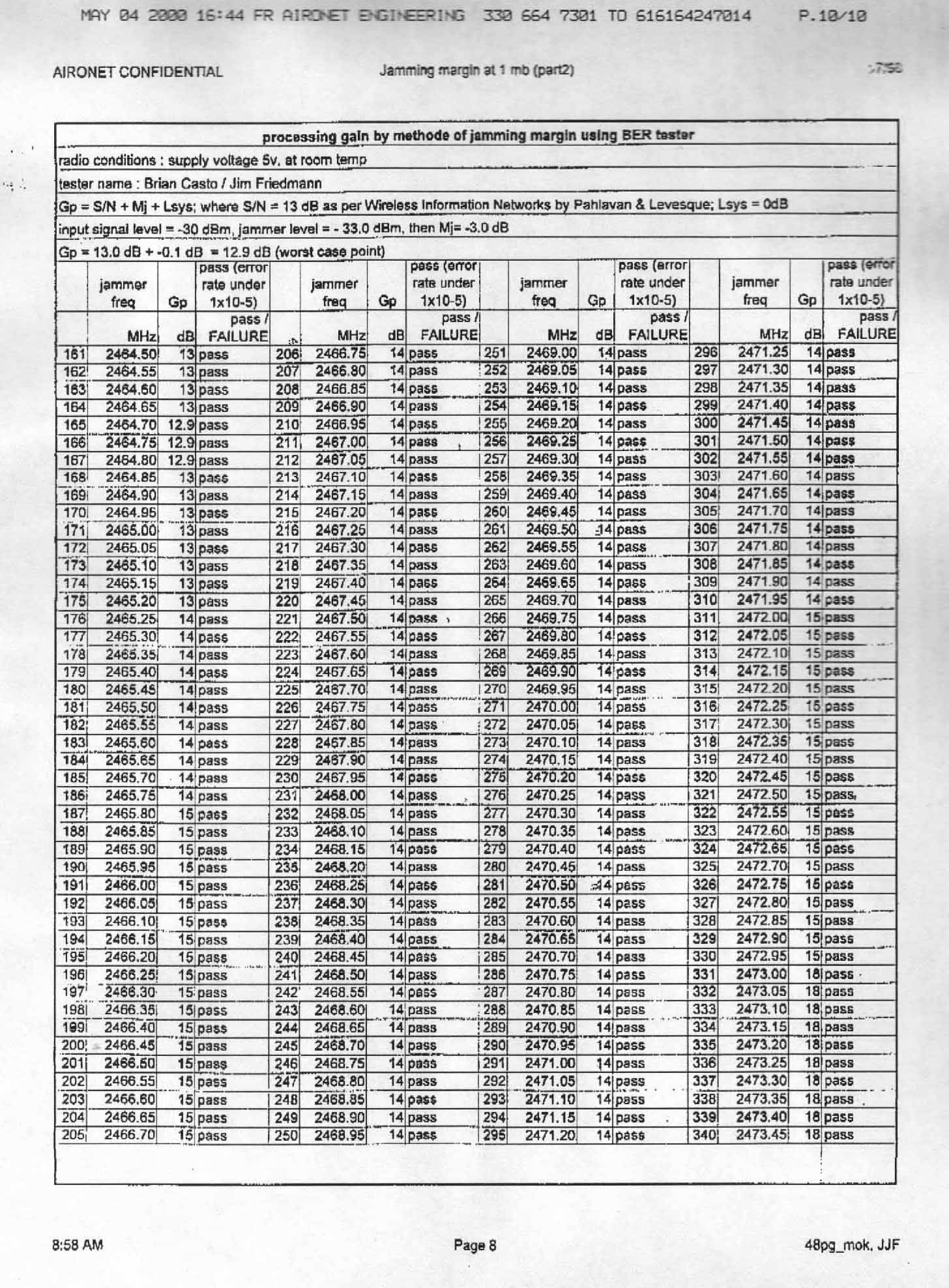
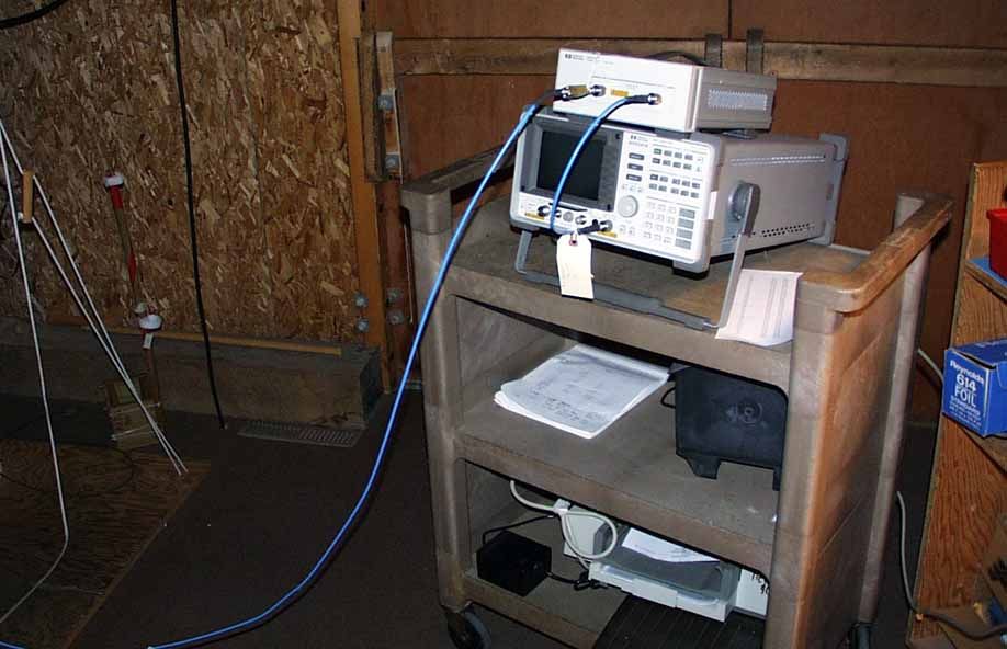
Test report #20000282FFCC 15.231 for MI-4800BFCC ID: LDK102039 Tested February 2, 2000 Aironet Confidential103/15/00 AHD EMC Lab, 92723 M152, Dowagiac, MI 49047, (616) 424-701491349 Exhibit D: Page 1 of 2 EXHIBIT D: P ROCESSING G AIN I NFORMATION [15.247( E )] PRODUCT NAME:AIRONET 4800B RADIO NAME OF TEST:The Processing Gain of a Direct Sequence System. FCC Part 15.247 (e) specifies: The processing gain of a direct sequence system shall be at least 10 dB. Guidance on measurement by FCC The processing gain may be measured using the CW jamming margin method. The test consists of stepping a signal generator in 50khz increments across the passband of the system. At each point, the generator level required to the produce the recommended Bit Error Rate (10-5) is recorded. This is the jammer level. The output power of the transmitting unit is measured at the same point. The Jammer to Signal (J/S) ratio is then calculated. Discard the worst 20% of the J/S data points. Total losses in a system including transmitter and receiver, should be assumed to be no more than 2 dB. therefore, processing gain = S/N + Mj + Lsys Where : S/N = Signal to noise ratio required at the receiver output for 10-5 error rate of a ideal receiver for your demodulation scheme Mj = Jammer to signal ratio Lsys = System losses (2dB max) Test results : for 1 mb data rate: S/N = 13 dB ; taken from Wireless Information Networks by Pahlavan & Levesque Mj = - 4.2 dB ; worst case jamming margin from tests in lab Lsys = 2.0 dB ; system losses therefore the processing gain at 1mb is 13 dB - 4.2 dB + 2.0 dB = 10.8 dB for 2 mb data rate: S/N = 13 dB ; taken from Wireless Information Networks by Pahlavan & Levesque Mj = - 4.2 dB ; worst case jamming margin from tests in lab Lsys = 2.0 dB ; system losses therefore the processing gain at 2mb is 13 dB – 4.2 dB + 2.0 dB = 10.8 dB Test report #20000282FFCC 15.231 for MI-4800BFCC ID: LDK102039 Tested February 2, 2000 Aironet Confidential203/15/00 AHD EMC Lab, 92723 M152, Dowagiac, MI 49047, (616) 424-701491349 Exhibit D: Page 2 of 2 for 5.5 mb data rate: S/N = 13.6 dB ; taken from Harris CCK encoding modulation Mj = - 4.4 dB ; worst case jamming margin from tests in lab (after 20% discard) Lsys = 2.0 dB ; system losses therefore the processing gain at 5.5mb is 13.6 dB - 4.4 dB + 2.0 dB = 11.2 dB for 11 mb data rate: S/N = 16.0 dB ; taken from Harris CCK encoding modulation Mj = - 7.4 dB ; worst case jamming margin from tests in lab (after 20% discarded) Lsys = 2.0 dB ; system losses therefore the processing gain at 11mb is 16.0 dB - 7.4 dB + 2.0 dB = 10.6 dB AI RONET CONFI DENTI AL RF Systems Engi neering dwg: J. Friedmann Fil e:FCC025_2.ds4 Date: 3/21/96 rev: 2. 4 Ghz SPREAD SPECTRUM RADIO, 2nd GEN Jammer Test, R240 eng: J. Friedmann Transmitter Jammi ng Test Setup AI RONET Si g GenPower Meter Recei ver Bit Error Rate Tester splitsum
RF Exposure Info
Test report #20000282FFCC 15.231 for MI-4800BFCC ID: LDK102039 Tested February 2, 2000 AHD EMC Lab, 92723 M152, Dowagiac, MI 49047, (616) 424-701499057 Exhibit M: Page 1 of 2 EXHIBIT M: RF E XPOSURE I NFORMATION [15.247( B 4),1.307( B 1),2.1093( C , D )] Engineering Analysis of Direct Sequence Spread Spectrum Transceiver Model MI4800B FCC ID: LDK102039 To Federal Communications Commission Part 1.1310 Radio Frequency Exposure Limits, Part 2.1093 RF Exposure Evaluation: Portable Devices, & OET 65 Supplement C 05/03/00 Test report #20000282FFCC 15.231 for MI-4800BFCC ID: LDK102039 Tested February 2, 2000 AHD EMC Lab, 92723 M152, Dowagiac, MI 49047, (616) 424-701499057 Exhibit M: Page 2 of 2 This analysis was done per the requirements of Part 15.247(b4) of the FCC rules as part of the FCC certification requirements for spread spectrum devices. The Aironet radio modules are designed for a maximum transmit output power of 100mW (+20dBm) and all calculations were based on that power . The test sample evaluated measured a transmit output power of approximately 18dBm. The unit is designed as a portable hand-held transmitter. This device will be utilized in the general population / uncontrolled areas. This category of devices are evaluated with respect to SAR limits for RF exposure. The applicable limit is 1.6W/Kg as averaged over any one gram of cube tissue. This limit is the ‘partial-body’ limit for uncontrolled exposure areas. A sample unit of model MI-4800B was sent to the University of Utah for SAR evaluation. This evaluation took place under the direction of professor Dr. Om Gandhi. The results of this SAR evaluation are: at +15dBm the SAR is .047W/Kg at +18dBm the SAR is .162W/Kg Dr. Gandhi’s report can be sent when it is available.
RF Exposure Info
SAR COMPLIANCE TESTING OF CISCO/AIRONET MODEL LDK102038 WIRELESS PC April 28, 2000 Submitted to:Mr. David A. Case NCE Senior Compliance Engineer Cisco Systems 3875 Embassy Parkway Akron, OH 44333 Submitted by:Om P. Gandhi Professor of Electrical Engineering University of Utah 50 S Central Campus Dr., Rm. 3280 Salt Lake City, UT 84112-9206 1 SAR COMPLIANCE TESTING OF CISCO/AIRONET MODEL LDK102038 WIRELESS PC I. Introduction The U.S. Federal Communications Commission (FCC) has adopted limits of human exposure to RF emissions from mobile and portable devices that are regulated by the FCC [1]. The FCC has also recently issued Supplement C (Edition 97-01) to OET Bulletin 65 defining both the measurement and the computational procedures that should be followed for evaluating compliance of mobile and portable devices with FCC limits for human exposure to radiofrequency emissions [2]. We have used the measurement procedure given in [2] to obtain peak 1-g SARs for the Cisco/Aironet Model LDK102038 Wireless PC. A photograph of this unit is shown in Fig. 1. As seen in Fig. 1, the RF antenna operating in the ISM frequency band 2412-2462 MHz is mounted at the back of the right-hand side of the keyboard. The Cisco/Aironet Model LDK102038 operates with a transmit power of up to 30 mW radiated from a printed patch antenna. Since the wireless PC may also be potentially placed on the lap where the RF antenna would be the closest to the body, a planar phantom model was used for all SAR measurements. II.The Tissue-Simulant Model The testing for the SAR distribution for the Cisco/Aironet Model LDK102038 Wireless PC was done with a planar rectangular box phantom model shown in Fig. 2. This box phantom of external dimensions 30 × 50 cm is filled with a tissue-simulant fluid up to a depth of 15.5 cm. To maintain flatness of the plantom, the rectangular box is made of acrylic 1 (ε r = 2.56) of thickness 6.35 mm. The tissue-simulant fluid uses a composition developed at the University of Utah which consists of 62.0% water, 37.0% sugar and 1% HEC. 2 For this composition, we have measured the dielectric properties using a Hewlett Packard (HP) Model 85070B Dielectric Probe in conjunction with HP Model 8720C Network Analyzer (50 MHz-20 GHz). The measured dielectric properties at the midband frequency of 2450 MHz are as follows: ε r = 51.3 ± 1.7 and σ = 1.76 ± 0.07 S/m. From reference 3, we obtain the desired dielectric properties to simulate the muscle tissue to be ε r = 52.7 and σ = 1.74 S/m. Thus, the measured properties for the muscle-simulant fluid are close to the desired values. III. The Measured SAR Distributions The SAR distribution was determined using the automated SAR measurement system developed at the University of Utah [4]. As described in [4], this SAR measurement system has been validated using a number of wireless telephones at 835 and 1900 MHz, respectively. The highest SAR region was identified in the first instance by using a coarser sampling with a step size of 8.0 mm over three overlapping areas for a total scan area of 8.0 × 9.6 cm. After identifying the region of the highest SAR, the SAR distribution was measured with a resolution of 2 mm in order to obtain the peak 1 cm 3 or 1-g SAR. The measured SAR distribution for the Cisco/Aironet Model LDK102038 Wireless PC operated in the maximum radiation mode (maximum radiated power of 30 mW) is given in Table 1. The peak 1-g SAR is determined to be 0.047 W/kg. IV. Comparison of the Data With FCC 96-326 Guidelines According to the FCC 96-326 Guidelines [1], the peak SAR for any 1-g of tissue should not exceed 1.6 W/kg. For the maximum radiated power condition, the Cisco/Aironet Model LDK102038 Wireless PC has been measured to give a peak 1-g SAR of 0.047 W/kg which is considerably smaller than 1.6 W/kg. 3 REFERENCES 1.Federal Communications Commission, "Guidelines for Evaluating the Environmental Effects of Radiofrequency Radiation," FCC 96-326, August 1, 1996. 2.K. Chan, R. F. Cleveland, Jr., and D. L. Means, "Evaluating Compliance With FCC Guidelines for Human Exposure to Radiofrequency Electromagnetic Fields," Supplement C (Edition 97-01) to OET Bulletin 65, December, 1997. Available from Office of Engineering and Technology, Federal Communications Commission, Washington D.C., 20554. 3.http://Sparc10.iroe.fi.cnr.it/tissprop/. 4.Q. Yu, O. P. Gandhi, M. Aronsson, and D. Wu, "An Automated SAR Measurement System for Compliance Testing of Personal Wireless Devices," IEEE Transactions on Electromagnetic Compatibility, Vol. 41(3), pp. 234-245, August 1999. 4 Table 1.The SARs measured for Cisco/Aironet Model LDK102038 Wireless PC. The SARs in W/kg are measured with a step size of 2 mm for the highest SAR region. 1-g SAR = 0.047 W/kg a. At depth of 1 mm 0.0360.0680.0660.0750.078 0.0550.0530.0620.0720.083 0.0830.0790.0820.0850.093 0.0740.0780.0810.0840.095 0.0790.0790.0850.0840.078 b. At depth of 3 mm 0.0410.0510.0510.0570.058 0.0490.0510.0550.0590.062 0.0580.0580.0610.0630.065 0.0560.0590.0620.0630.069 0.0610.0620.0640.0650.062 c. At depth of 5 mm 0.0430.0370.0390.0420.042 0.0430.0480.0470.0460.044 0.0380.0410.0440.0450.043 0.0420.0430.0470.0460.048 0.0460.0480.0470.0480.049 d. At depth of 7 mm 0.0400.0260.0290.0300.029 0.0370.0430.0380.0360.031 0.0240.0280.0310.0310.027 0.0300.0310.0350.0340.032 0.0350.0360.0340.0360.040 e. At depth of 9 mm 0.0340.0180.0220.0210.020 0.0300.0360.0290.0270.022 0.0150.0200.0220.0200.017 0.0220.0220.0260.0250.022 0.0270.0270.0250.0270.033 5 Fig. 1.Photograph of Cisco/Aironet Model LD…
Text truncated - open the document above for the full version.
Contact Information
Applicant
Samuel Kim(Manager, Engineering)
Technical Contact
Aironet Wireless CommunicationsDavid A Case
[email protected]330-664-7396
3875 Embassy Parkway · Akron, Ohio · United States
Non-Technical Contact
Aironet Wireless CommunicationsDavid A Case
[email protected]330-664-7396
Test Firm
AHD EMC LaboratoryGordon Helm
Technical Specifications
| # | Rule Parts | Frequency Range | Power Output |
|---|---|---|---|
| 1 | 15C | 2.41 GHz - 2.46 GHz | 33.00 mW |
Other Applications from Cisco Systems Inc

LDKJ98213058
May 25, 2026Wireless Phone
Equipment Class
DSS - Part 15 Spread Spectrum TransmitterLDKIW9165E
Aug 20, 2024Wi-Fi 6E Outdoor Access Point
Equipment Class
6SD - 15E 6 GHz Standard Power Access PointLDKIW9165DH
Aug 05, 2024Wi-Fi 6E Outdoor Access Point
Equipment Class
6SD - 15E 6 GHz Standard Power Access PointLDKUSBC2857
Jul 22, 2024Cisco Headset USB-C Adapter
Equipment Class
DSS - Part 15 Spread Spectrum TransmitterLDKESPRD2922
May 09, 2024UC Phone
Equipment Class
NII - Unlicensed National Information Infrastructure TX