LDK102041Spread Spectrum Transmitter
Cisco Systems Inc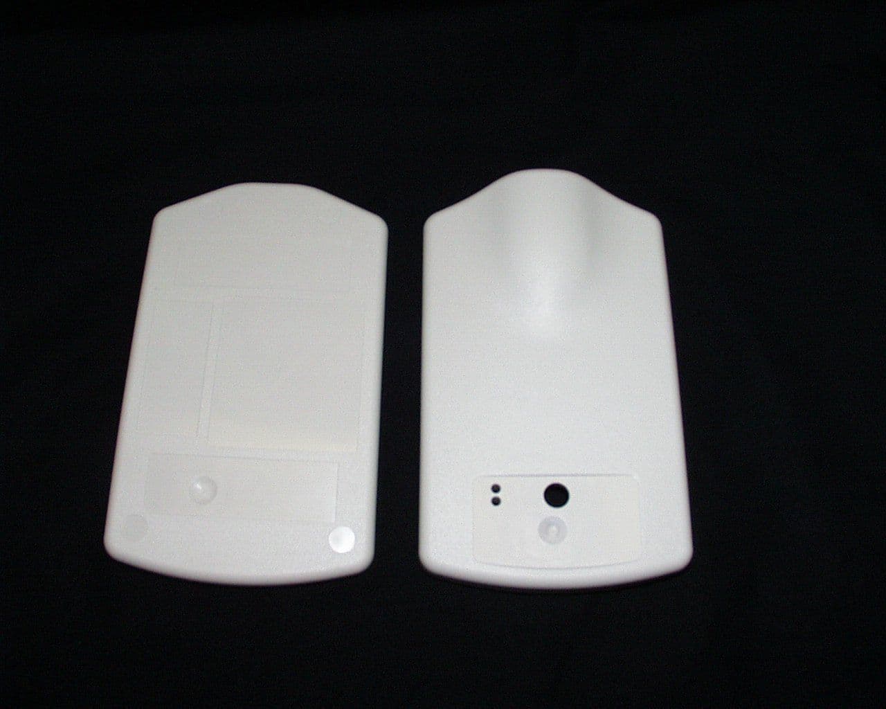
Click to zoom
Application Details
- Equipment Class
- DSS - Part 15 Spread Spectrum Transmitter
- Date of Grant
- Dec 18, 2000
- Application Purpose
- Original Equipment
- Date of Application
- Sep 26, 2000
- Equipment Note
- Spread Spectrum Transmitter
- Frequency Range
- 2412.00000000 - 2462.00000000
- Company
- Cisco Systems Inc
- Country
- United States
Documents & Files
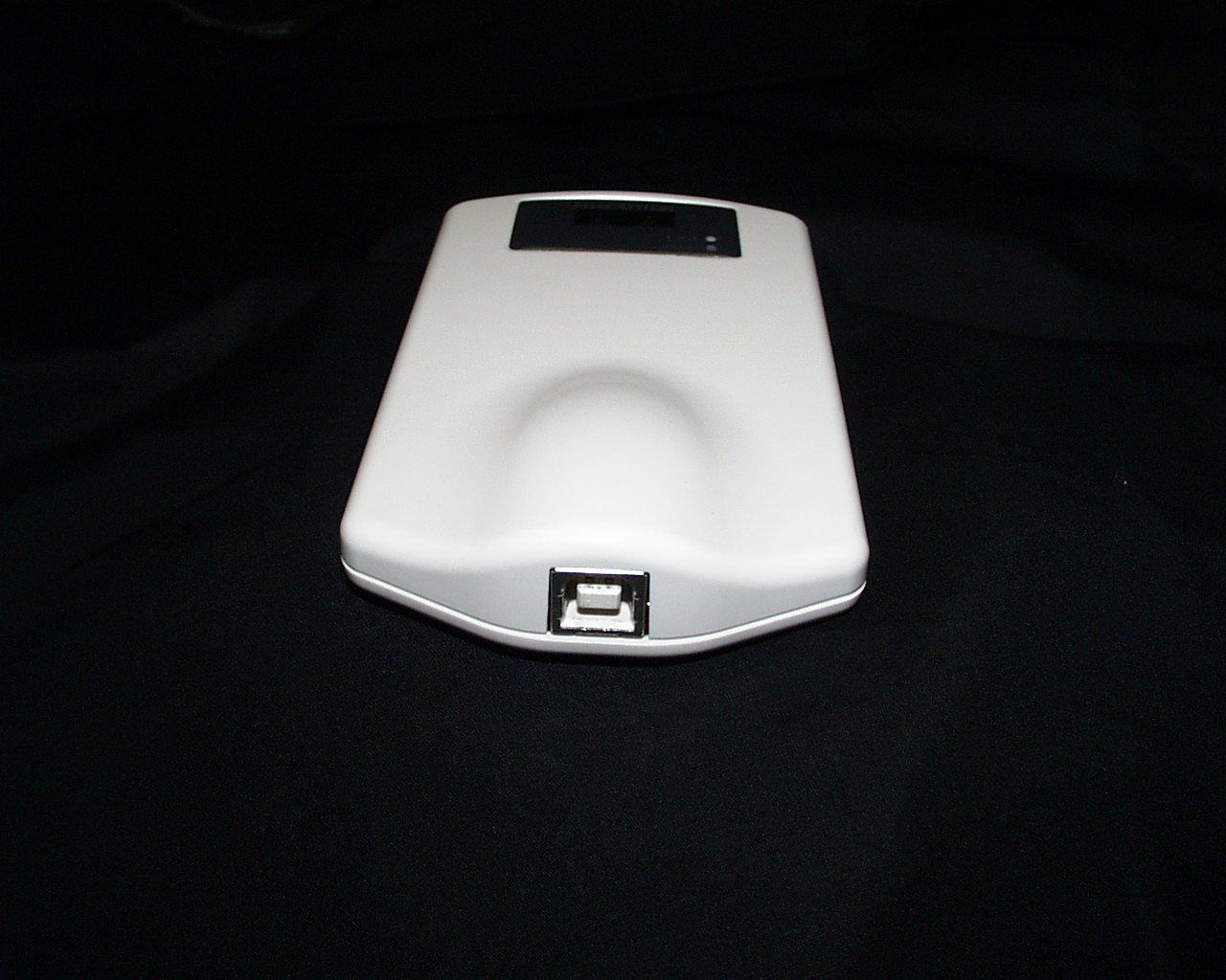
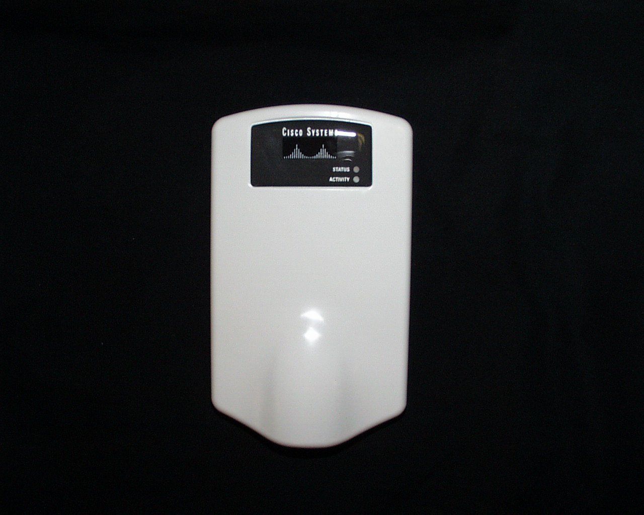
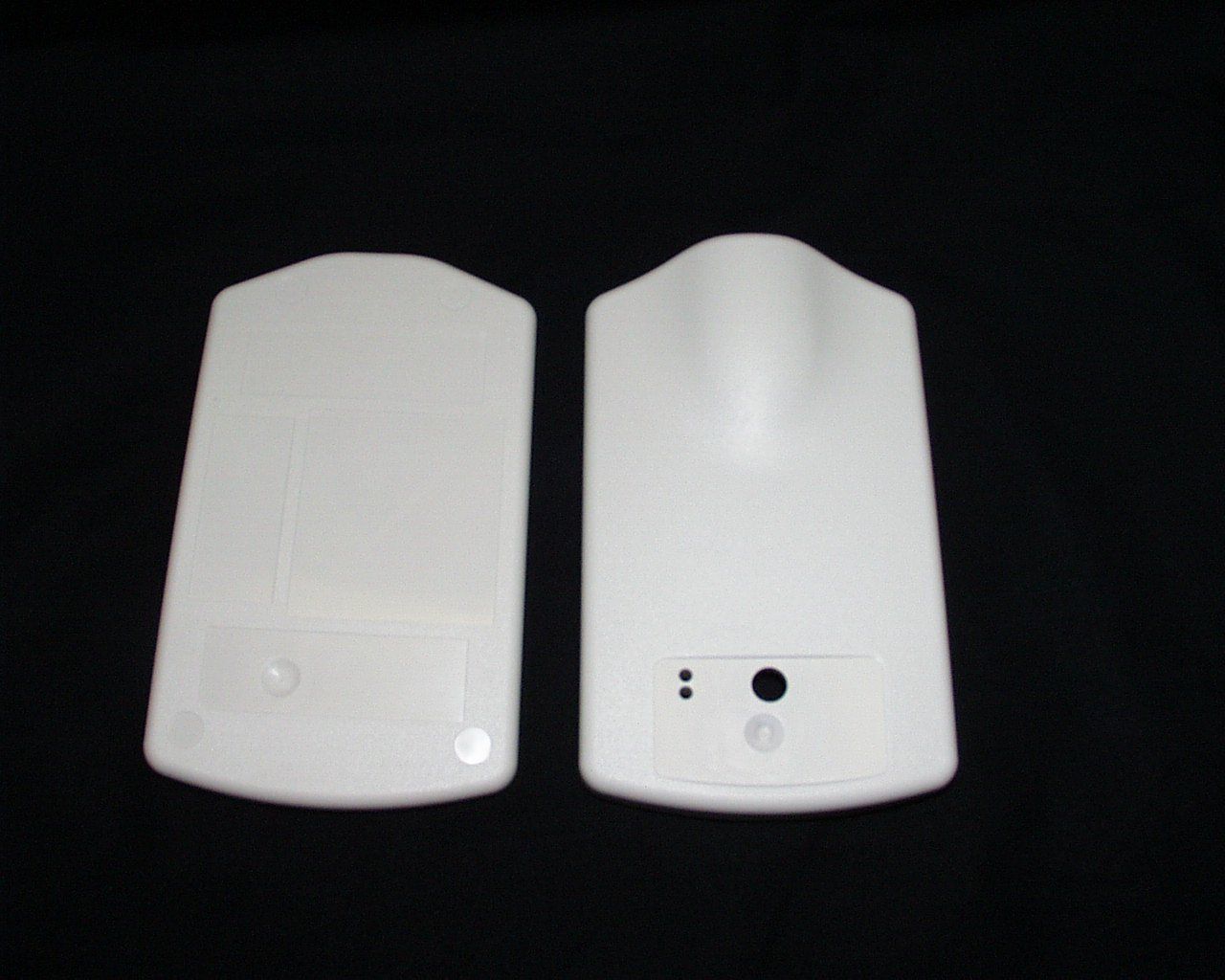
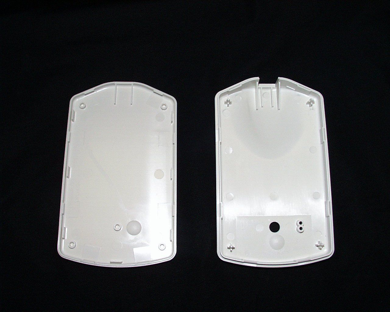
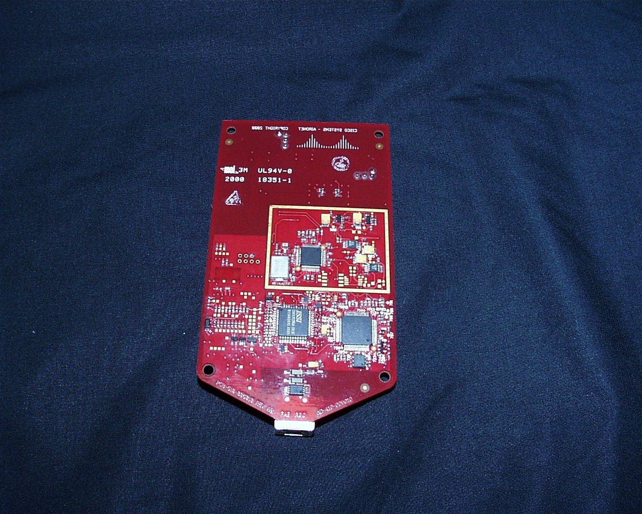
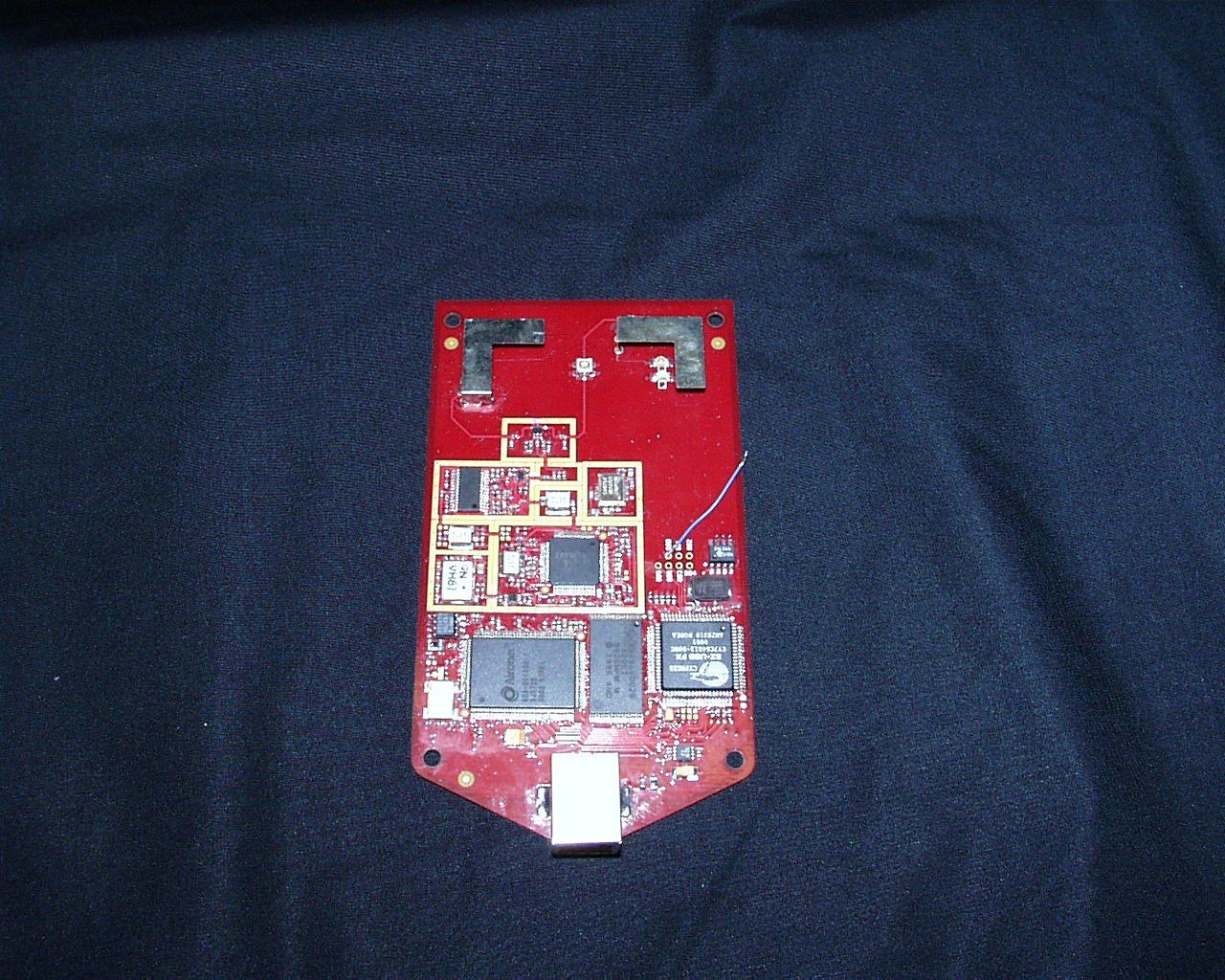
Document Text
Text extracted from the exhibit documents filed with the FCC. Open a document above to read the original.
Users Manual
T AKE O UT W HAT Y OU NEED I NSTALL THE USB C LIENT A DAPTER I NSTALL THE D RIVER AND U TILITIES 1 2 3 Quick Start Guide C ISCO A IRONET 340 S ERIES USB C LIENT A DAPTER 1 Take Out What You Need •Cisco Aironet 340 Series USB Client Adapter (labeled Wireless USB Adapter) •USB cable (2-meter) •Velcro Strips •Cisco Aironet 340 Series USB Client Adapter CD for Windows 98, Windows 2000 and Windows ME with software and product documentation If any item is missing or damaged, contact your Cisco representative or reseller for support. Computer Requirements A computing device (desktop or laptop computer) equipped with a USB port. All drivers and supporting software for the USB port must be loaded and configured. Check to see that you have the following items: 2 Install the USB Client Adapter Overview The Cisco Aironet 340 Series USB Client Adapter will operate in a wide range of environments but will deliver maximum performance if the adapter is installed in the best possible configuration. Here is the optimum configuration for the adapter: •Positioned so the curved surface of the adapter faces in the direction of the Access Point •Installed vertically on a wall, the higher on the wall the better •The 2-meter cable connected directly between the adapter and the USB port on the computer The instructions that follow describe alternate or non-ideal conditions that will work, but could contribute to reduced system performance. The further you deviate from optimum conditions, the more likely you will degrade performance. If your operating environment prevents an optimum installation, refer to the Software Configuration Guide and the Link Test Utility which is a tool for testing and optimizing performance under marginal conditions. Multiple USB Devices For optimum performance, connect the adapter cable directly into the computer’s USB port. If you are using more than one USB device, install a multi-port USB hub. The adapter is powered by the computer, so attaching other devices will increase power drain from the computer. To avoid excessive power drain when using more that one USB device, install the adapter into a self-powered hub. Follow these steps to install the adapter: 1 Select an operating location. For optimum performance, use only the 2-meter cable supplied with the adapter. Using an extension USB cable could degrade system performance. 2 Position the adapter vertically on a wall, the higher on the wall better. If no wall is available, the adapter can rest horizontally on a flat surface but you will get reduced system performance. Position the curved face of the adapter in the direction of the Access Point. 3 3 Mount the adapter. The adapter includes Velcro mounting strips with a peel-off backing. If installing the adapter on a flat non-fabric surface, use both black and white strips. Leave black loops attached to white hooks. Peel off white strip backing and attach to adapter. Peel off black strip backing and attach to wall. If installing adapter on a fabric wall, there is no need to attach the black loop strip to the wall. The white hook strip will adhere to fabric. 4 Power up the computer. You will connect the adapter to the USB port while the computer is running. 5 Install the USB Adapter CD. 6 Connect the USB cable between the adapter and the USB port. The operating system will detect the new hardware and start the configuration sequence. 4 Install the Driver and Utilities Note: The following procedures assume you are installing the driver from the CD provided. If your PC does not have a CD-ROM drive, download the driver from Cisco’s web site. After you have installed the USB client adapter, the system automatically detects it, opens a New Hardware Found window, and starts collecting information for a driver database. Follow these steps to install the drivers: 1 When the Add New Hardware Wizard dialog box opens, it is searching for new drivers. Click Next . 2 From the next dialog box, select Search for the best driver for your device (Recommended) and click Next . 3 If asked which drive to choose to load drivers, select CD-ROM drive and deselect all other options. 4 The hardware wizard will find the installation files on the CD and display the search results. When the USB adapter driver is displayed, click Next to copy the required files. 5 During driver installation, you may be prompted to enter a path to the required client adapter or Windows files: (a) Windows files installed on your PC are usually located in the folder C:\Windows\Options\Cabs. Click OK to install. (b) If the system prompts you for the Windows CD and the CD-ROM drive on your PC is drive D, the path should be D:\WIN(either 98, 2K, or ME). Click OK to copy the required files. 6 The Add New Hardware Wizard window again opens indicating that the installation is complete. Click Finish. 7 Remove the CD and restart your laptop. 5 Follow these steps to install the utilities: After you have installed the appropriate driver for your system, you can install the Cisco Aironet Client Utilities (ACU), Link Status Meter (LSM), and Client Encryption Manager (CEM) utilities. Installing utilities is optional unless using Wired Equivalent Privacy (WEP) in your network. If WEP is enabled, all devices in the network must have the same WEP code, which you set using the CEM utility. The ACU and LSM utilities provide troubleshooting and status information, but are not required. 1 Insert the CD-ROM for your operating system into your computer CD-ROM drive. 2 Select Start > Run and enter the following path (where D is the letter for your CD-ROM drive): D:\utils\setup.exe 3 Follow the setup instructions on the screen to complete the installation. Refer to Software Configuration Guide on the Client Adapter CD for instructions on how to use each utility. Note: After you have installed the appropriate driver and utilities, contact your IS department if you have a problem connecting to the network. 6 Safety Information for the Cisco Aironet 340 Seri…
Text truncated - open the document above for the full version.
Users Manual
T AKE O UT W HAT Y OU NEED I NSTALL THE USB C LIENT A DAPTER I NSTALL THE D RIVER AND U TILITIES 1 2 3 Quick Start Guide C ISCO A IRONET 340 S ERIES USB C LIENT A DAPTER 1 Take Out What You Need •Cisco Aironet 340 Series USB Client Adapter (labeled Wireless USB Adapter) •USB cable (2-meter) •Velcro Strips •Cisco Aironet 340 Series USB Client Adapter CD for Windows 98, Windows 2000 and Windows ME with software and product documentation If any item is missing or damaged, contact your Cisco representative or reseller for support. Computer Requirements A computing device (desktop or laptop computer) equipped with a USB port. All drivers and supporting software for the USB port must be loaded and configured. Check to see that you have the following items: 2 Install the USB Client Adapter Overview The Cisco Aironet 340 Series USB Client Adapter will operate in a wide range of environments but will deliver maximum performance if the adapter is installed in the best possible configuration. Here is the optimum configuration for the adapter: •Positioned so the curved surface of the adapter faces in the direction of the Access Point •Installed vertically on a wall, the higher on the wall the better •The 2-meter cable connected directly between the adapter and the USB port on the computer The instructions that follow describe alternate or non-ideal conditions that will work, but could contribute to reduced system performance. The further you deviate from optimum conditions, the more likely you will degrade performance. If your operating environment prevents an optimum installation, refer to the Software Configuration Guide and the Link Test Utility which is a tool for testing and optimizing performance under marginal conditions. Multiple USB Devices For optimum performance, connect the adapter cable directly into the computer’s USB port. If you are using more than one USB device, install a multi-port USB hub. The adapter is powered by the computer, so attaching other devices will increase power drain from the computer. To avoid excessive power drain when using more that one USB device, install the adapter into a self-powered hub. Follow these steps to install the adapter: 1 Select an operating location. For optimum performance, use only the 2-meter cable supplied with the adapter. Using an extension USB cable could degrade system performance. 2 Position the adapter vertically on a wall, the higher on the wall better. If no wall is available, the adapter can rest horizontally on a flat surface but you will get reduced system performance. Position the curved face of the adapter in the direction of the Access Point. 3 3 Mount the adapter. The adapter includes Velcro mounting strips with a peel-off backing. If installing the adapter on a flat non-fabric surface, use both black and white strips. Leave black loops attached to white hooks. Peel off white strip backing and attach to adapter. Peel off black strip backing and attach to wall. If installing adapter on a fabric wall, there is no need to attach the black loop strip to the wall. The white hook strip will adhere to fabric. 4 Power up the computer. You will connect the adapter to the USB port while the computer is running. 5 Install the USB Adapter CD. 6 Connect the USB cable between the adapter and the USB port. The operating system will detect the new hardware and start the configuration sequence. 4 Install the Driver and Utilities Note: The following procedures assume you are installing the driver from the CD provided. If your PC does not have a CD-ROM drive, download the driver from Cisco’s web site. After you have installed the USB client adapter, the system automatically detects it, opens a New Hardware Found window, and starts collecting information for a driver database. Follow these steps to install the drivers: 1 When the Add New Hardware Wizard dialog box opens, it is searching for new drivers. Click Next . 2 From the next dialog box, select Search for the best driver for your device (Recommended) and click Next . 3 If asked which drive to choose to load drivers, select CD-ROM drive and deselect all other options. 4 The hardware wizard will find the installation files on the CD and display the search results. When the USB adapter driver is displayed, click Next to copy the required files. 5 During driver installation, you may be prompted to enter a path to the required client adapter or Windows files: (a) Windows files installed on your PC are usually located in the folder C:\Windows\Options\Cabs. Click OK to install. (b) If the system prompts you for the Windows CD and the CD-ROM drive on your PC is drive D, the path should be D:\WIN(either 98, 2K, or ME). Click OK to copy the required files. 6 The Add New Hardware Wizard window again opens indicating that the installation is complete. Click Finish. 7 Remove the CD and restart your laptop. 5 Follow these steps to install the utilities: After you have installed the appropriate driver for your system, you can install the Cisco Aironet Client Utilities (ACU), Link Status Meter (LSM), and Client Encryption Manager (CEM) utilities. Installing utilities is optional unless using Wired Equivalent Privacy (WEP) in your network. If WEP is enabled, all devices in the network must have the same WEP code, which you set using the CEM utility. The ACU and LSM utilities provide troubleshooting and status information, but are not required. 1 Insert the CD-ROM for your operating system into your computer CD-ROM drive. 2 Select Start > Run and enter the following path (where D is the letter for your CD-ROM drive): D:\utils\setup.exe 3 Follow the setup instructions on the screen to complete the installation. Refer to Software Configuration Guide on the Client Adapter CD for instructions on how to use each utility. Note: After you have installed the appropriate driver and utilities, contact your IS department if you have a problem connecting to the network. 6 Safety Information for the Cisco Aironet 340 Seri…
Text truncated - open the document above for the full version.
Attestation Statements
MFA p0070020, d0090017 DECLARATION OF CONFORMITY (UNINTENTIONAL RADIATOR) for MODEL: AIR-USB340 FCC ID: LDK102041 to FEDERAL COMMUNICATIONS COMMISSION RULE PART 15, SUBPART B - UNINTENTIONAL RADIATORS CLASS B LIMITS. DATE OF AMENDED REPORT: December 12, 2000 ON THE BEHALF OF THE APPLICANT: Cisco Systems Inc AT THE REQUEST OF : P.O. 394296 Cisco Systems Inc 3875 Embassy Parkway Akron, OH 44333 Attention of: David A. Case, NCE, Senior Compliance Engineer (330) 664-7396; FAX: -7301 Email: [email protected] SUPERVISED BY: Morton Flom, P. Eng. MFA p0070020, d0090017 FCC ID: LDK102041 MFA p0070020, d0090017 0 TABLE OF CONTENTS RULEDESCRIPTIONPAGE . Test Report 1 2.947 General Information 3 15.109 Spurious Emissions (Radiated) 6 FCC ID: LDK102041 MFA p0070020, d0090017 PAGE NO.1of15. Required information per ISO/IEC Guide 25-1990, paragraph 13.2: a) TEST REPORT b) Laboratory: (FCC: 31040/SIT) (Canada: IC 2044) M. Flom Associates, Inc. 3356 N. San Marcos Place, Suite 107 Chandler, AZ 85225 c) Report Number: d0090017 d) Client: Cisco Systems Inc 3875 Embassy Parkway Akron, OH 44333 e) Identification: AIR-USB340 FCC ID: LDK102041 Description: Spread Spectrum Radio f) EUT Condition: Not required unless specified in individual tests. g) Report Date: September 12, 2000 EUT Received: July 20, 2000 h, j, k): As indicated in individual tests. i) Sampling method: No sampling procedure used. l) Uncertainty: In accordance with MFA internal quality manual. m) Supervised by: Morton Flom, P. Eng. n) Results: The results presented in this report relate only to the item tested. o) Reproduction: This report must not be reproduced, except in full, without written permission from this laboratory. FCC ID: LDK102041 MFA p0070020, d0090017 PAGE NO.2of15. M. Flom Associates, Inc. is accredited by the American Association for Laboratory Association (A2LA) as shown in the scope below. "This laboratory is accredited by the American Association for Laboratory Accreditation (A2LA) and the results shown in this report have been determined in accordance with the laboratory's terms of accreditation unless stated otherwise in the report." Should this report contain any data for tests for which we are not accredited, or which have been undertaken by a subcontractor that is not A2LA accredited, such data would not covered by this laboratory's A2LA accreditation. FCC ID: LDK102041 MFA p0070020, d0090017 PAGE NO.3of15. GENERAL INFORMATION Part 2.947: MEASUREMENT PROCEDURE 15.101: AUTHORIZATION OF UNINTENTIONAL RADIATORS GUIDE: MEASUREMENT PROCEDURE ANSI C63.4-1992/2000 DESCRIPTION OF MEASUREMENT FACILITIES: FILE: 31040/SIT A description of the measurement facilities was filed with the Commission and was found to be in compliance with the requirements of Section 2.948, by letter dated March 3, 1997. All pertinent changes will be reported to the Commission by up-date prior to March 2000. NOTE: The equipment under test was connected with all accessories as normally supplied, and was operated in accordance with the manufacturer's specifications. The data herein is to indicate that the equipment under test has been found to comply with the FCC Rules Part 15 Subpart B Class B Limits. DATE OF TESTS : July 2000 PERSONNEL: STAFF AT M. FLOM ASSOCIATES, INC. NOTE: This report must not be reproduced, except in full, without written permission from this laboratory. FCC ID: LDK102041 MFA p0070020, d0090017 PAGE NO.4of15. TECHNICAL REPORT 1. (a) NAME AND ADDRESS OF MANUFACTURER: Cisco Systems Inc 170 West Tasman Drive San Jose, CA 95134-1706 (b) MODEL NO: AIR-USB340 (c) TRADE NAME: Cisco (d) EQUIPMENT UNDER TEST (EUT) DESCRIPTION: Spread Spectrum Radio (e) THE EUT's NORMAL OPERATING LOCATION IS : Module 2. ACCESSORIES : Qty Type Make, Model S/N FCC ID 1 Laptop Toshiba PRT800U 29337228U-3 CJ6PN-25452-MS-E FCC ID: LDK102041 MFA p0070020, d0090017 PAGE NO.5of15. 3. CABLES: Qty Type Length, m Shield Shielded Hood Ferrite N/A FOR ALL TESTS: a. Interface cables were positioned so as to maximize the emissions during testing. b. Cables draped and bundled individually. c. Cables were arranged and moved in all planes to maximize emissions. d. External monitor connected (a) to auxiliary AC outlet and then (b) to floor-mounted AC outlet. e. Photographs show worst case conditions. In accordance with ANSI C63.4-1992/2000, section 6.1.9, and unless otherwise indicated in the specific measurement results, the ambient temperature of the actual EUT was maintained within the range of 10°to 40°C (50°to 104°F) unless the particular equipment requirements specify testing over a different temperature range. Also, unless otherwise indicated, the humidity levels were in the range of 10% to 90% relative humidity. 4. MODIFICATIONS : (none) 15.31: MEASUREMENT STANDARD & PROCEDURE: IEEE STANDARD 187 WAS USED AS A GUIDE. FCC MEASUREMENT PROCEDURE MP-1 x ANSI 63.4 (1992/2000) “Methods of measurement od radio-noise emissions from low-voltage electrical and electronic equipment in the range of 9 kHz to 40 GHz.” FCC ID: LDK102041 MFA p0070020, d0090017 PAGE NO.6of15. NAME OF TEST: Radiated Spurious Emissions SPECIFICATION: 15.109: Radiated Interference Limits 15.209: Radiated Emission Limits; General Requirements 15.33: Frequency Range of Radiated Measurements 80.217: Suppression of Interference Aboard Ships GUIDE: ANSI C63.4-1992/2000 TEST EQUIPMENT: See attached test setup TEST CONFIGURATION OF EUT: 1. The equipment was installed in a typical system and configured in accordance with the manufacturer's instructions. It was also operated in a manner which is representative of the typical usage for the EUT. 2. The equipment and I/O cable(s) were re-arranged to maximize each emission. For each change in configuration, the system was rotated through 360°. The antenna height was changed from one to six meters. Both horizontal and vertical polarization scans were used. The worst case is here reported. 3. For EUTs normally operated on top of a table, tests were performed with the EUT…
Text truncated - open the document above for the full version.
ID Label/Location Info
2 1 3 4 5 6 NOTES: UNLESS OTHERWISE SPECIFIED 1) REFERENCE BOM'S xxxxxxxxxxxxxxxxxxxxxx . 2) SHALL MEET MECHANICAL ACCEPTANCE SPEC., DOCUMENT NO. 5-0669-XX . 3) PLACE SERIAL LABEL APPROX. AS SHOWN. REFER TO CISCO SPECIFICATION FOR LABEL AND PRINTING REQUIREMENT, DOCUMENT NO. 701806-0000. ASSEMBLY PROCEDURE: 1) MOUNT ITEM 1HOLES INTO ITEM 2 LOCATING PINS, ORIENTED AS SHOWN 2) SNAP ITEM 3 TO ITEM 2 3) ASSEMBLE ITEM 4 TO ITEM 2, ORIENTED AS SHOWN 4) ASSEMBLE ITEMS 5 & 6 TO ITEM 3, ORIENTED AS SHOWN 5) ASSEMBLE ITEM 7 (QTY 4) TO ITEM 3 7 TYP 4 PLCS 8 D C B A 8 7 6 5 43 2 1 A B C D 1 2 3 4 5 6 7 X.X = .030 X.XX = .015 X.XXX = .005 ANGULAR = 0-30' MATERIAL: FINISH: UNLESS OTHERWISE SPECIFIED DIMENSIONS ARE IN INCHES: TOLERANCES: THIS DRAWING CONTAINS INFORMATION WHICH IS THE PROPRIETARY PROPERTY OF CISCO SYSTEMS. THIS DRAWING IS CONFIDENTIAL AND ITS CONTENTS MAY NOT BE DISCLOSED WITHOUT PRIOR WRITTEN CONSENT OF CISCO SYSTEMS. APPROVALDATE DES: ENG: MFG: JAM 7/28/00 SIZE DWG NO. B 62-6387-01 REFDWG, ASY, ELMECH, COMET SCALE: 1:1 DO NOT SCALE DRAWING SHT1OF 1 CAD TYPE: SOLIDWORKS REV A0 REV A0 DESCRIPTION ---REVISION--- ECN APPROVE MECH MFG INITIAL RELEASE 6057 JAM MODEL FILE:62-6387-01
Operational Description
Aironet Confidential 4 9/27/00 AI RONET CONFI DENTI AL RF Systems Engi neering dwg: J. Friedmann File:FCC025_2.ds4 Date: 3/21/96 rev: 2. 4 Ghz SPREAD SPECTRUM RADI O, 2nd GEN Jammer Test, R240 eng: J. Friedmann Transmitter Jammi ng Tes t Set up AI RONET Si g GenPower Meter Recei ver Bit Error Rate Tester splitsum
Operational Description
Aironet Confidential 2 9/27/00 PRODUCT NAME: Cisco Systems AIR-LMC34X RADIO NAME OF TEST: The Processing Gain of a Direct Sequence System. FCC Part 15.247 (e) specifies: The processing gain of a direct sequence system shall be at least 10 dB. Guidance on measurement by FCC The processing gain may be measured using the CW jamming margin method. The test consists of stepping a signal generator in 50khz increments across the passband of the system. At each point, the generator level required to the produce the recommended Bit Error Rate (10-5) is recorded. This is the jammer level. The output power of the transmitting unit is measured at the same point. The Jammer to Signal (J/S) ratio is then calculated. Discard the worst 20% of the J/S data points. Total losses in a system including transmitter and receiver, should be assumed to be no more than 2 dB. therefore, processing gain = S/N + Mj + Lsys Where : S/N = Signal to noise ratio required at the receiver output for 10-5 error rate of a ideal receiver for your demodulation scheme Mj = Jammer to signal ratio Lsys = System losses (2dB max) Test results : for 1 mb data rate: S/N = 13 dB ; taken from Wireless Information Networks by Pahlavan & Levesque Mj = - 4.2 dB ; worst case jamming margin from tests in lab Lsys = 2.0 dB ; system losses therefore the processing gain at 1mb is 13 dB - 4.2 dB + 2.0 dB = 10.8 dB for 2 mb data rate: S/N = 13 dB ; taken from Wireless Information Networks by Pahlavan & Levesque Mj = - 4.2 dB ; worst case jamming margin from tests in lab Lsys = 2.0 dB ; system losses therefore the processing gain at 2mb is 13 dB – 4.2 dB + 2.0 dB = 10.8 dB Aironet Confidential 3 9/27/00 for 5.5 mb data rate: S/N = 13.6 dB ; taken from Harris CCK encoding modulation Mj = - 4.4 dB ; worst case jamming margin from tests in lab (after 20% discard) Lsys = 2.0 dB ; system losses therefore the processing gain at 5.5mb is 13.6 dB - 4.4 dB + 2.0 dB = 11.2 dB for 11 mb data rate: S/N = 16.0 dB ; taken from Harris CCK encoding modulation Mj = - 7.4 dB ; worst case jamming margin from tests in lab (after 20% discarded) Lsys = 2.0 dB ; system losses therefore the processing gain at 11mb is 16.0 dB - 7.4 dB + 2.0 dB = 10.6 dB
Operational Description
CISCO CONFIDENTIALMercury processing gainJ. Friedmann data ratesmodulation usedsymbol rateschip ratechip per bit 10 log (chip per bit) add 3dB if unique codes for I & Q (minus 1 dB for implementation) theoretical processing gain dB (add last two columns) measured processing gain 1 mb/sBPSK1 mbps11 mbps 11 (same code for I & Q)10.7 dB10.7 dB10.8 dB 2 mb/sQPSK1 mbps11 mbps 11 (same code for I & Q)10.7 dB10.7 dB10.8 dB 5.5 mb/sCCK1.375 mbps8 mbps 8 (8 for I & 8 for Q)9 dB2 dB11 dB10.7 dB 11 mb/sCCK1.375 mbps8 mbps 8 (8 for I & 8 for Q)9 dB2 dB11 dB10.6 dB 9/25/001PG_Mercury_th_writeup.xls
Operational Description
Figure 1. Mechanical Drawing of the Comet Inverted-F Antenna Electrical Testing - VSWR. The mechanical dimensions were optimized for 2:1 VSWR bandwidth of 100 MHz centered around 2450 MHz. Test results on two separate primary and secondary antennas are shown in Figures 2 – 5 below.
Operational Description
CISCO CONFIDENTIALMercury processing gainJ. Friedmann data ratesmodulation usedsymbol rateschip ratechip per bit 10 log (chip per bit) add 3dB if unique codes for I & Q (minus 1 dB for implementation) theoretical processing gain dB (add last two columns) measured processing gain 1 mb/sBPSK1 mbps11 mbps 11 (same code for I & Q)10.7 dB10.7 dB10.8 dB 2 mb/sQPSK1 mbps11 mbps 11 (same code for I & Q)10.7 dB10.7 dB10.8 dB 5.5 mb/sCCK1.375 mbps8 mbps 8 (8 for I & 8 for Q)9 dB2 dB11 dB10.7 dB 11 mb/sCCK1.375 mbps8 mbps 8 (8 for I & 8 for Q)9 dB2 dB11 dB10.6 dB 9/25/001PG_Mercury_th_writeup.xls
Parts List/Tune Up Info
Aironet Confidential 5 9/27/00 LM340 Spread Spectrum Transceiver Alignment Procedures Set power out: put radio in TX mode, use power meter to set power out. 1)TX on,ch 12-84: set power amp output power by adjusting voltage to the IF attenuator in the tx chain. This is done by software, which changes the DAC voltage output. TX power out; set power to +15dBm + 1dB /-1 dB for highest power setting
Parts List/Tune Up Info
BOM-410-005010 This document includes the followin g assembl y variations: Variation Title Descri p tion -001 64k-bit EEPROM 64k-bit EEPROM -002 128-bit EEPROM 128-bit EEPROM 19-May-00 BOM-410-005010 PAGE 1 OF 11 RUN PCA , COMET BILL OF MATERIALS THE INFORMATION CONTAINED HEREIN IS PROPRIETARYANY REPRODUCTION OR DISCLOSURE OF THIS DRAWN: Susan Wagner APPROVAL: Steve Cloud 19-May-00 CHECKED: DOCUMENT IS FORBIDDEN, EXCEPT WITH WRITTENTO AIRONET WIRELESS COMMUNICATIONS INC.PERMISSION FROM AIRONET WIRELESS COMMUNICATIONS. REV DESCRIPTION ECN AB0 2445 INCORPORATED ECN REVISIONS A PPROVED Aironet Wireless Communications, Inc. Fairlawn, Ohio 44333 h a a a a NOTE: SEE SOURCE CONTROL DRAWINGS FOR ORDERING INFORMATION. Part Number Value/Item Description Reference Designator Rev Item Qty Fab Assy -001: 64k-bit EEPROM Doc ( A ) Cell PCB1 PCB , COMET PCB 510-005010 AB 1AB0 1 SHLD1 SHIELD , POWER AMP SHIELD 530-004913 A1 1 2 SHIELD SHLD6 SHIELD, I/Q MODEM SHIELD 530-004919 A1 1 3 SHIELD SHLD3 SHIELD, RF/IF SHIELD 530-004939 B0 1 4 SHIELD SHLD2 SHIELD , 2GHZ VCO SHIELD 530-005061 A0 1 5 SHIELD SHLD8 SHIELD , TX BPF SHIELD 530-005062 B0 1 6 SHIELD ANT1 ANT2 FABMTL , ANTENNA , COMET ANTENNA , COMET 530-005513 2 7 ANTRT U502 U505 U802 VOLTAGE REGULATOR, 500MA PEAK OUTPUT LDO MIC5219-3.3BMM 601-004136-033 3 8 UMAX8 U704 IC , UHS INVERTER , TINYLOGIC ( TM ) UHS SINGLE INV 601-004165 1 9 USV U500 U501 VOLTAGE REGULATOR , 150MA CMOS LDO TC1185-2.8VCT 601-004325-0280 2 10 SMV U400 IC , RF/IF CONVERTER & SYNTHESIZER 2.4GHZ HFA3683A 601-004748 1 11 LQFP64 U503 IC , I/Q MODULATOR/DEMOD & SYNTHESIZER HFA3783IN 601-004749 1 12 TQFP48 U101 IC, POWER AMPLIFIER & DETECTOR, 2.4GHZ HFA3983IV 601-004802 1 13 TSSP29 U401 IC , SILICON MMIC WIDEBAND AMP , 3V , 2.7GHZ UPC2745TB 601-004866 1 14 SMM6 U1 U100 IC , GAAS RF SWITCH , SPDT , 2.5GHZ AS179-92 601-004904 2 15 SOT363 U900 U901 IC , UHS INVERTER W/SCHMITT TRIGER INPUT UHS SCHMITT INV 601-005712 2 16 USV U701 U705 U708 LMOS, 2-INPUT AND GATE TC7S08FU 604-002976 3 17 USV U600 IC,2MBIT BOTTOM SECTOR, LO VOLTAGE FLASH AM29LV002BB-120EC 605-003571-120C 1 18 TSOP40 U706 IC , SRAM , 128K X 16 , 3.3V , CMOS SRAM 128Kx16 15ns , C 605-004901-015 1 19 TQFP44 U800 IC , IIC 8K X 8 SERIAL EEPROM 24LC64-/SN 605-005694 1 20 SO8 U710 IC , SILICON SERIAL NUMBER DS2401AP 606-002904 1 21 TSOC6 U707A IC, DSSS BASEBAND PROCESSOR, 11MB, CCK HFA3861BIN 607-005388 1 22 TQFP64 U601 PROCESSOR, A503 CUSTOM EMBEDDED ASIC A503 608-004808 1 23 TQ128W U801 IC , EZ-USB FX MICRO-CONTROLLER , 80-PIN CY7C64603-80NC 608-005506 1 24 PQFP80 Q900 TRANSISTOR , NPN , GENERAL - SMD MMBT2222A 611-000047 1 25 SOT23 Q700 Q701 TRANSISTOR , SILICON NPN W/BUILTIN RESIS B=10K/BE=NONE 611-002986-14T 2 26 SSM U902 DUAL USB TRANSIENT SUPPRESSOR SN75240PW 613-005517-COM 1 27 TSSOP8 R931 RESISTOR , 1/10W 5% - SMD 0.0 620-000131-000 1 28 0805 R815 RESISTOR , 1/10W 5% - SMD 1.0M 620-000131-1M0 1 29 0805 R302 R413 R415 R417 R418 R420 R503 RESISTOR , 1/16W , 5% - SMD 0.0 620-003251-000 22 30 0402 R520 R707 R711 R715 R721 R727 R728 19-May-00 BOM-410-005010 PAGE 2 OF 11 RUN PCA , COMET BILL OF MATERIALS THE INFORMATION CONTAINED HEREIN IS PROPRIETARYANY REPRODUCTION OR DISCLOSURE OF THIS DRAWN: Susan Wagner APPROVAL: Steve Cloud 19-May-00 CHECKED: DOCUMENT IS FORBIDDEN, EXCEPT WITH WRITTENTO AIRONET WIRELESS COMMUNICATIONS INC.PERMISSION FROM AIRONET WIRELESS COMMUNICATIONS. REV DESCRIPTION ECN AB0 2445 INCORPORATED ECN REVISIONS A PPROVED Aironet Wireless Communications, Inc. Fairlawn, Ohio 44333 h a a a a NOTE: SEE SOURCE CONTROL DRAWINGS FOR ORDERING INFORMATION. Part Number Value/Item Description Reference Designator Rev Item Qty Fab Assy -001: 64k-bit EEPROM (Cont'd) Doc ( A ) Cell R729 R733 R812 R813 R903 R912 R914 R919 R400 R501 R508 R737 RESISTOR, 1/16W, 5% - SMD 100 620-003251-100 4 31 0402 R613 R700 R701 R732 R807 R811 R814 RESISTOR , 1/16W , 5% - SMD 10K 620-003251-10K 15 32 0402 R905 R906 R907 R909 R910 R913 R917 R918 R105 R107 R308 R414 R516 R600 R612 RESISTOR , 1/16W , 5% - SMD 10 620-003251-10R 7 33 0402 R305 R403 R411 RESISTOR, 1/16W, 5% - SMD 18 620-003251-18R 3 34 0402 R101 R900 R902 R915 RESISTOR , 1/16W , 5% - SMD 1.0K 620-003251-1K0 4 35 0402 R412 R416 RESISTOR , 1/16W , 5% - SMD 1.1K 620-003251-1K1 2 36 0402 R306 R610 R930 RESISTOR , 1/16W , 5% - SMD 1.5K 620-003251-1K5 3 37 0402 R805 RESISTOR , 1/16W , 5% - SMD 1.0M 620-003251-1M0 1 38 0402 R402 RESISTOR, 1/16W, 5% - SMD 20 620-003251-20R 1 39 0402 R806 R929 RESISTOR , 1/16W , 5% - SMD 22 620-003251-22R 2 40 0402 R500 R506 RESISTOR , 1/16W , 5% - SMD 2.0K 620-003251-2K0 2 41 0402 R301 R304 R401 R404 R409 R410 RESISTOR , 1/16W , 5% - SMD 300 620-003251-300 6 42 0402 R505 R748 RESISTOR, 1/16W, 5% - SMD 3.9K 620-003251-3K9 2 43 0402 R741 R743 R908 RESISTOR, 1/16W, 5% - SMD 470 620-003251-470 3 44 0402 R611 R744 R745 R746 R747 RESISTOR , 1/16W , 5% - SMD 47K 620-003251-47K 5 45 0402 R1 R100 R104 R106 R2 R50 R51 R517 RESISTOR , 1/16W , 5% - SMD 51 620-003251-51R 9 46 0402 R522 R307 R725 RESISTOR, 1/16W, 5% - SMD 680 620-003251-680 2 47 0402 R601 R602 R603 R604 R605 R606 R708 RESISTOR, 1/16W, 5% - SMD 68K 620-003251-68K 29 48 0402 R719 R720 R722 R724 R730 R731 R735 R736 R740 R800 R801 R802 R803 R804 R920 R921 R922 R923 R924 R925 R926 R927 R309 R310 RESISTOR , 1/16W , 5% - SMD 82 620-003251-82R 2 49 0402 R311 RESISTOR , 1/16W , 5% - SMD 91 620-003251-91R 1 50 0402 R406 RESISTOR , 1/16W 1% -SMD 11.5K 620-003521-11K5 1 51 0402 R705 R712 R716 R718 RESISTOR , 1/16W 1% -SMD 124 620-003521-124R 4 52 0402 19-May-00 BOM-410-005010 PAGE 3 OF 11 RUN PCA , COMET BILL OF MATERIALS THE INFORMATION CONTAINED HEREIN IS PROPRIETARYANY REPRODUCTION OR DISCLOSURE OF THIS DRAWN: Susan Wagner APPROVAL: Steve Cloud 19-May-00 CHECKED: DOCUMENT IS FORBIDDEN, EXCEPT WITH WRITTENTO AIRONET WIRELESS COMMUNICATIONS INC.PERMISSION FROM AIRONET WIRELESS COMMUNICATIONS. REV DESCRIPTION ECN AB0 2445 INCORPORATED ECN REVISIONS A PPROVED Aironet Wireless Communications, Inc. Fairlawn, Ohio 44333 …
Text truncated - open the document above for the full version.
RF Exposure Info
T AKE O UT W HAT Y OU NEED I NSTALL THE USB C LIENT A DAPTER I NSTALL THE D RIVER AND U TILITIES 1 2 3 Quick Start Guide C ISCO A IRONET 340 S ERIES USB C LIENT A DAPTER 1 Take Out What You Need •Cisco Aironet 340 Series USB Client Adapter (labeled Wireless USB Adapter) •USB cable (2-meter) •Velcro Strips •Cisco Aironet 340 Series USB Client Adapter CD for Windows 98, Windows 2000 and Windows ME with software and p…
Text truncated - open the document above for the full version.
Contact Information
Applicant
Samuel Kim(Manager, Engineering)
Technical Contact
M. Flom Associates, IncMorton Flom
[email protected]480 926 3100
3356 N. San Marcos Pl., Suite 107 · Chandler, Arizona · United States
Non-Technical Contact
M. Flom Associates, Inc.Morton Flom
[email protected]480 926 3100
Test Firm
M. Flom Associates, Inc.Morton Flom
Technical Specifications
| # | Rule Parts | Frequency Range | Power Output |
|---|---|---|---|
| 1 | 15C | 2.41 GHz - 2.46 GHz | 30.00 mW |
Other Applications from Cisco Systems Inc

LDKJ98213058
May 25, 2026Wireless Phone
Equipment Class
DSS - Part 15 Spread Spectrum TransmitterLDKIW9165E
Aug 20, 2024Wi-Fi 6E Outdoor Access Point
Equipment Class
6SD - 15E 6 GHz Standard Power Access PointLDKIW9165DH
Aug 05, 2024Wi-Fi 6E Outdoor Access Point
Equipment Class
6SD - 15E 6 GHz Standard Power Access PointLDKUSBC2857
Jul 22, 2024Cisco Headset USB-C Adapter
Equipment Class
DSS - Part 15 Spread Spectrum TransmitterLDKESPRD2922
May 09, 2024UC Phone
Equipment Class
NII - Unlicensed National Information Infrastructure TX