LDK102042AIR-MPI352
Cisco Systems Inc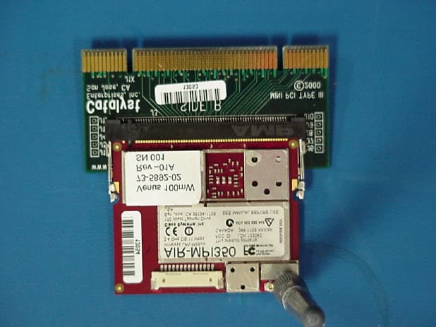
Click to zoom
Application Details
- Equipment Class
- DSS - Part 15 Spread Spectrum Transmitter
- Date of Grant
- May 29, 2001
- Application Purpose
- Original Equipment
- Date of Application
- Mar 08, 2001
- Equipment Note
- AIR-MPI352
- Frequency Range
- 2412.00000000 - 2462.00000000
- Company
- Cisco Systems Inc
- Country
- United States
Documents & Files
Document Text
Text extracted from the exhibit documents filed with the FCC. Open a document above to read the original.
Users Manual
360 Herndon Parkway Suite 1400 Herndon, VA 20170 http://www.rheintech.com Certification Report For: Cisco System Page 40 Document Number: 2001041 Revision 3 23 MANUAL C-1 Cisco Aironet AIR-MPI352 OL-XXXX-0X APPENDIXC Declarations of Conformity and Regulatory Information This appendix provides declarations of conformity and regulatory information for the Cisco Aironet AIR-MPI352. The following topics are covered in this section: •Manufacturers Federal Communication Commission Declaration of Conformity Statement, page C-2 •Industry of Canada Spectrum Management, page C-3 •Safety Information for the AIR-MPI352, page C-4 •European Community, Switzerland, Norway, Iceland, and Liechtenstein, page C-6 •Declaration of Conformity for RF Exposure, page C-8 Appendix C Declarations of Conformity and Regulatory Information Manufacturers Federal Communication Commission Declaration of Conformity Statement C-2 Cisco Aironet AIR-MPI352 OL-XXXX-0X Manufacturers Federal Communication Commission Declaration of Conformity Statement Models:AIR-MPI352 FCC Certification Number:LDK102042 Manufacturer:Cisco Systems, Inc. 170 West Tasman Drive San Jose, CA 95134-1706 USA This device complies with Part 15 rules. Operation is subject to the following two conditions: 1.This device may not cause harmful interference, and 2.This device must accept any interference received, including interference that may cause undesired operation. This equipment has been tested and found to comply with the limits of a Class B digital device, pursuant to Part 15 of the FCC Rules. These limits are designed to provide reasonable protection against harmful interference when the equipment is operated in a residential environment. This equipment generates, uses, and radiates radio frequency energy, and if not installed and used in accordance with the instructions, may cause harmful interference. However, there is no guarantee that interference will not occur. If this equipment does cause interference to radio or television reception, which can be determined by turning the equipment off and on, the user is encouraged to correct the interference by one of the following measures: •Reorient or relocate the receiving antenna. •Increase separation between the equipment and receiver. Tested To Comply With FCC Standards FOR HOME OR OFFICE USE C-3 Cisco Aironet AIR-MPI352 OL-XXXX-0X Appendix C Declarations of Conformity and Regulatory Information Industry of Canada Spectrum Management •Connect the equipment to an outlet on a circuit different from which the receiver is connected. •Consult the dealer or an experienced radio/TV technician. CautionThe Part 15 radio device operates on a non-interference basis with other devices operating at this frequency. Any changes or modification to said product not expressly approved by Cisco could void the user’s authority to operate this device. NoteThe following label must be affixed to the OEM product containing the Cisco Aironet AIR-MPI352 product: This device contains: FCC ID: LDK102042 CANADA: 246 1103 XXXXX Industry of Canada Spectrum Management Canadian Compliance Statement This Class B Digital apparatus meets all the requirements of the Canadian Interference-Causing Equipment Regulations. Cet appareil numerique de la classe B respecte les exigences du Reglement sur le material broilleur du Canada. This device complies with Class B Limits of Industry Canada. Operation is subject to the following two conditions: 1.This device may not cause harmful interference, and 2.This device must accept any interference received, including interference that may cause undesired operation. Appendix C Declarations of Conformity and Regulatory Information Safety Information for the AIR-MPI352 C-4 Cisco Aironet AIR-MPI352 OL-XXXX-0X The device is certified to the requirements of RSS-210 for 2.4-GHz spread spectrum devices. The use of this device in a system operating either partially or completely outdoors may require the user to obtain a license for the system according to the Canadian regulations. For further information, contact your local Industry Canada office. Safety Information for the AIR-MPI352 The Federal Communications Commission (FCC) with its action in ET Docket 96-8 has adopted a safety standard for human exposure to RF electromagnetic energy emitted by FCC certified equipment. Cisco Aironet Mini PCI product meets the uncontrolled environmental limits found in OET-65 and ANSI C95.1, 1991. Proper operation of this radio according to the instructions found in this manual and the hardware and software guides on the Cisco Aironet Series Wireless LAN Adapters CD will result in user exposure that is substantially below the FCC recommended limits. •Do not touch or move the antenna(s) while the unit is transmitting or receiving. •Do not hold any component containing a radio such that the antenna is very close to or touching any exposed parts of the body, especially the face or eyes, while transmitting. •Do not operate the radio or attempt to transmit data unless the antenna is connected; otherwise, the radio may be damaged. •Use in specific environments: –Do not operate a portable transmitter near unshielded blasting caps or in an explosive environment unless it is a type especially qualified for such use. –The use of wireless devices in hazardous locations is limited to the constraints posed by the safety directors of such environments. –The use of wireless devices on airplanes is governed by the Federal Aviation Administration (FAA). –The use of wireless devices in hospitals is restricted to the limits set forth by each hospital. C-5 Cisco Aironet AIR-MPI352 OL-XXXX-0X Appendix C Declarations of Conformity and Regulatory Information Safety Information for the AIR-MPI352 –In order to comply with FCC RF exposure limits, high gain antennas should be located at a minimum distance of 7.9 inches (20 cm) or more from the body of all persons when used in a mobile or fixed type application. WarningIn order to comply with RF …
Text truncated - open the document above for the full version.
Cover Letter(s)
March 1, 2001 Federal Communications Commission 7435 Oakland Mills Road Columbia, MD 21046 To Whom It May Concern: The following information is to be held confidential pursuant of 47 CFR Part 0 §0.457 and Section 552(b)(4) of the Freedom of Information Act, because the information provided contains trade secrets and proprietary. If made public, the information might be used to the disadvantage of the applicant in the market place. Schematics Product Description Hardware Functional Specification Best Regards, Don Sloan Director, EAG WNBU Engineering
External Photos
360 Herndon Parkway Suite 1400 Herndon, VA 20170 http://www.rheintech.com Certification Report For: Cisco System Page 46 Document Number: 2001041 Revision 3 26 EXTERNAL PHOTOGRAPHS 360 Herndon Parkway Suite 1400 Herndon, VA 20170 http://www.rheintech.com Certification Report For: Cisco System Page 47 Document Number: 2001041 Revision 3 27 ANTENNA PHOTOGRAPHS Antenna Antenna port
External Photos
Certification Report For: Cisco System Page 1 Document Number: 2001041 Revision 3 antennae Photographs Inverted F Inverted F antenna PCB from antenna Certification Report For: Cisco System Page 2 Document Number: 2001041 Revision 3 Dipole diversity Dipole Diversity antenna PCB from Dipole Diversity antenna Certification Report For: Cisco System Page 3 Document Number: 2001041 Revision 3 CHIP Chip antenna
External Photos
360 Herndon Parkway Suite 1400 Herndon, VA 20170 http://www.rheintech.com Certification Report For: Cisco System Page 84 Document Number: 2001041 Revision 4 APPENDIX J: ANTENNA PHOTOGRAPHS PHOTOGRAPH 10: DIPOLE CISCO ANTENNA PHOTOGRAPH 11: : DIPOLE CISCO ANTENNA PORT 360 Herndon Parkway Suite 1400 Herndon, VA 20170 http://www.rheintech.com Certification Report For: Cisco System Page 85 Document Number: 2001041 Revision 4 PHOTOGRAPH 12: DELL INVERTED F ANTENNA Inverted F antenna PCB from antenna 360 Herndon Parkway Suite 1400 Herndon, VA 20170 http://www.rheintech.com Certification Report For: Cisco System Page 86 Document Number: 2001041 Revision 4 PHOTOGRAPH 13: DELL DIPOLE ANTENNA Dipole antenna PCB from Dipole Diversity antenna 360 Herndon Parkway Suite 1400 Herndon, VA 20170 http://www.rheintech.com Certification Report For: Cisco System Page 87 Document Number: 2001041 Revision 4 PHOTOGRAPH 14: TOSHIBA CHIP ANTENNA Chip antenna 360 Herndon Parkway Suite 1400 Herndon, VA 20170 http://www.rheintech.com Certification Report For: Cisco System Page 88 Document Number: 2001041 Revision 4 PHOTOGRAPH 15: TOSHIBA INVERTED F ANTENNA Inverted F
ID Label/Location Info
360 Herndon Parkway Suite 1400 Herndon, VA 20170 http://www.rheintech.com Certification Report For: Cisco System Page 38 Document Number: 2001041 Revision 3 21 LABEL INFORMATION Location Please see information on the following pages
Internal Photos
360 Herndon Parkway Suite 1400 Herndon, VA 20170 http://www.rheintech.com Certification Report For: Cisco System Page 43 Document Number: 2001041 Revision 3 25 INTERNAL PHOTOGRAPHS Top View Bottom View 360 Herndon Parkway Suite 1400 Herndon, VA 20170 http://www.rheintech.com Certification Report For: Cisco System Page 44 Document Number: 2001041 Revision 3 Top view of the board without cover Bottom view of the board without cover 360 Herndon Parkway Suite 1400 Herndon, VA 20170 http://www.rheintech.com Certification Report For: Cisco System Page 45 Document Number: 2001041 Revision 3 Antenna port on the board
RF Exposure Info
360 Herndon Parkway Suite 1400 Herndon, VA 20170 http://www.rheintech.com Certification Report For: Cisco System Page 35 Document Number: 2001041 Revision 3 18 RF EXPOSURE CALCULATIONS FOR HIGH GAIN ANTENNAS From FCC 1.1310 table 1A, the maximum permissible RF exposure for an uncontrolled environment is 1mW/cm 2. The Electric field generated for a 1mW/cm 2 exposure (S) is calculated as follows: S = E 2 /Z where: S = Power density E = Electric field Z = Impedance. E = √S x Z 1mW/cm 2 = 10 W/m 2 The impedance of free space is 337 ohms, where E and H fields are perpendicular. Thus: E = √10 x 377 = 61.4 V/m which is equivalent to 1mW/cm 2 Using the relationship between Electric field E, Power in watts P, and distance in meters d, the corresponding Antenna numeric gain G and the transmitter output power and solving for d, d = √ P eak x 30 x G E Example using the Stub Omni-directional antenna 1. The Numeric gain G of antenna with a gain specified in dB is determined by: G = Log –1 (dB gain/10) G = Log –1 0.22 = 1.66 The table below identifies the distances where the 1mW/cm 2 exposure limits may be exceeded during continuous transmission using the external antenna Antenna Type Gain (dBi) Gain Numeric Peak output EIRP Power (mW) Calculated RF Exposure Separation Distance (cm) Minimum RF Exposure Separation Distance (cm) External 2.2 1.66 177.8 4.8 20
RF Exposure Info
CELLTECH RESEARCH INC. Test Report S/N: 030801-71LDK 1955 Moss Court, Kelowna, Date(s) of Tests: March 16, 2001 B.C. CANADA V1Y 9L3 _________________________________________________________________________________________________________ © 2001 Celltech Research Inc. CERTIFICATE OF COMPLIANCE SAR EVALUATION This wireless mobile and/or portable device has been shown to be compliant for localized Specific Absorption Rate (SAR) for uncontrolled environment/general exposure limits specified in ANSI/IEEE Std. C95.1-1992 and had been tested in accordance with the measurement procedures specified in ANSI/IEEE Std. C95.3-1999. I attest to the accuracy of data. All measurements were performed by me or were made under my supervision and are correct to the best of my knowledge and belief. I assume full responsibility for the completeness of these measurements and vouch for the qualifications of all persons taking them. Celltech Research Inc. certifies that no party to this application has been denied FCC benefits pursuant to Section 5301 of the Anti-Drug Abuse Act of 1988, 21 U.S.C. 853(a). Shawn McMillen General Manager Celltech Research Inc. Test Lab: CELLTECH RESEARCH INC. Testing and Engineering Lab 1955 Moss Court Kelowna, B.C. Canada V1Y 9L3 Phone: 250 - 860-3130 Fax: 250 - 860-3110 Toll Free: 1-877-545-6287 e-mail: [email protected] web site: www.globuswireless.com Applicant Information: CISCO SYSTEMS INC. 3875 Embassy Parkway, Suite 350 Akron, OH 44333 Attn: Jim Nicholson Tel. (330) 664-7362 Fax. (330) 664-7301 FCC ID: LDK102042 Model(s): AIR-MPI352 Equipment Type: Wireless LAN Mini-PCI Card Equipment Classification: Part 15 Spread Spectrum Transmitter Modulation: Direct Sequence Spread Spectrum (DSSS) Tx Frequency Range: 2412 - 2462 MHz RF Output Power Tested: Max. Power FCC Rule Part(s): 15.247, 2.1093; ET Docket 96.326 IC Rule Part(s): RSS-210, RSS-102 CELLTECH RESEARCH INC. Test Report S/N: 030801-71LDK 1955 Moss Court, Kelowna, Date(s) of Tests: March 16, 2001 B.C. CANADA V1Y 9L3 _________________________________________________________________________________________________________ © 2001 Celltech Research Inc. TABLE OF CONTENTS 1.0 INTRODUCTION.................................................................. 1 2.0 DESCRIPTION OF EUT.......................................................... 1 3.0 SAR MEASUREMENT SYSTEM ............................................. 2 4.0 MEASUREMENT SUMMARY.................................................. 3 5.0 SAR LIMITS........................................................................ 3 6.0 DETAILS OF SAR EVALUATION............................................ 4 7.0 EVALUATION PROCEDURES................................................. 5 8.0 SYSTEM VALIDATION.......................................................... 5 9.0 SIMULATED EQUIVALENT TISSUES...................................... 6 10.0 TISSUE PARAMETERS......................................................... 6 11.0 SYSTEM SPECIFICATIONS.................................................... 7 12.0 TEST EQUIPMENT LIST........................................................ 8 13.0 MEASUREMENT UNCERTAINTIES........................................ 9 14.0 REFERENCES...................................................................... 10 APPENDIX A - SAR MEASUREMENT DATA........................................ 11 APPENDIX B - DIPOLE VALIDATION................................................ 12 APPENDIX C - PROBE CALIBRATION............................................... 13 APPENDIX D - TEST SETUP PHOTOGRAPHS..................................... 14 CELLTECH RESEARCH INC. Test Report S/N: 030801-71LDK 1955 Moss Court, Kelowna, Date(s) of Tests: March 16, 2001 B.C. CANADA V1Y 9L3 _________________________________________________________________________________________________________ © 2001 Celltech Research Inc. CISCO SYSTEMS INC. FCC ID: LDK102042 1 2.4GHz Spread Spectrum Wireless LAN Mini-PCI Card 1.0 INTRODUCTION This measurement report shows compliance of the CISCO SYSTEMS INC. AIR-MPI352 2.4GHz Direct Sequence Spread Spectrum Wireless LAN Mini-PCI Card FCC ID: LDK102042 with FCC Part 2.1093, ET Docket 96-326 Rules and IC RSS-102 for mobile and portable devices. The test procedures, as described in American National Standards Institute C95.1-1992 (1), FCC OET Bulletin 65-1997 were employed. A description of the product and operating configuration, detailed summary of the test results, methodology and procedures used in the evaluation, equipment used, and the various provisions of the rules are included within this test report. 2.0 DESCRIPTION of Equipment Under Test (EUT) EUT Type Wireless LAN Mini-PCI Card FCC ID LDK102042 Equipment Class Part 15 Spread Spectrum Transmitter Model No.(s) AIR-MPI352 Modulation Direct Sequence Spread Spectrum S/N No. Pre-production FCC Rule Part 15.247, 2.1093; ET Docket 96.326 IC Rule Part RSS-210 RSS-102 Tx Frequency Range (MHz) 2412 - 2462 RF Output Power Tested Max. Power Antenna Type Ultra-Miniature SMT GSC Type Antenna Length 96 mm CELLTECH RESEARCH INC. Test Report S/N: 030801-71LDK 1955 Moss Court, Kelowna, Date(s) of Tests: March 16, 2001 B.C. CANADA V1Y 9L3 _________________________________________________________________________________________________________ © 2001 Celltech Research Inc. CISCO SYSTEMS INC. FCC ID: LDK102042 2 2.4GHz Spread Spectrum Wireless LAN Mini-PCI Card 3.0 SAR MEASUREMENT SYSTEM Celltech Research SAR measurement facility utilizes the Dosimetric Assessment System (DASY™) manufactured by Schmid & Partner Engineering AG (SPEAG™) of Zurich, Switzerland. The DASY system is comprised of the robot controller, computer, near-field probe, probe alignment sensor, and the generic twin phantom containing brain or muscle equivalent material. The robot is a six-axis industrial robot performing precise movements to position the probe to the location (points) of maximum electromagnetic field (EMF). A cell controller system cont…
Text truncated - open the document above for the full version.
RF Exposure Info
360 Herndon Parkway Suite 1400 Herndon, VA 20170 http://www.rheintech.com Certification Report For: Cisco System Page 71 Document Number: 2001041 Revision 4 APPENDIX A: RF EXPOSURE CALCULATIONS FOR HIGH GAIN ANTENNAS From FCC 1.1310 table 1A, the maximum permissible RF exposure for an uncontrolled environment is 1mW/cm 2. The Electric field generated for a 1mW/cm 2 exposure (S) is calculated as follows: S = E 2 /Z where: S = Power density E = Electric field Z = Impedance. E = √S x Z 1mW/cm 2 = 10 W/m 2 The impedance of free space is 337 ohms, where E and H fields are perpendicular. Thus: E = √10 x 377 = 61.4 V/m which is equivalent to 1mW/cm 2 Using the relationship between Electric field E, Power in watts P, and distance in meters d, the corresponding Antenna numeric gain G and the transmitter output power and solving for d, d = √ P eak x 30 x G E Example using the Stub Omni-directional antenna 1. The Numeric gain G of antenna with a gain specified in dB is determined by: G = Log –1 (dB gain/10) G = Log –1 0.22 = 1.66 The table below identifies the distances where the 1mW/cm 2 exposure limits may be exceeded during continuous transmission using the external antenna 360 Herndon Parkway Suite 1400 Herndon, VA 20170 http://www.rheintech.com Certification Report For: Cisco System Page 72 Document Number: 2001041 Revision 4 TABLE 24: CISCO DIPOLE ANTENNA Antenna Type Gain (dBi) Gain Numeric Peak output EIRP Power (mW) Calculated RF Exposure Separation Distance (cm) Minimum RF Exposure Separation Distance (cm) External 2.2 1.66 177.8 4.8 20 TABLE 25: DELL DIPOLE ANTENNA Antenna Type Gain (dBi) Gain Numeric Peak output EIRP Power (mW) Calculated RF Exposure Separation Distance (cm) Minimum RF Exposure Separation Distance (cm) External -5.6 0.27 30.0 1.5 20 TABLE 26: DELL INVERTED F ANTENNA Antenna Type Gain (dBi) Gain Numeric Peak output EIRP Power (mW) Calculated RF Exposure Separation Distance (cm) Minimum RF Exposure Separation Distance (cm) External -5.6. 0.27 30.0 1.5 20 TABLE 27: TOSHIBA CHIP ANTENNA Antenna Type Gain (dBi) Gain Numeric Peak output EIRP Power (mW) Calculated RF Exposure Separation Distance (cm) Minimum RF Exposure Separation Distance (cm) External 2.1 1.6 176.8 3.7 20 TABLE 28: TOSHIBA INVERTED F ANTENNA Antenna Type Gain (dBi) Gain Numeric Peak output EIRP Power (mW) Calculated RF Exposure Separation Distance (cm) Minimum RF Exposure Separation Distance (cm) External 1.0 1.25 137.2 3.6 20
RF Exposure Info
CELLTECH RESEARCH INC. Test Report S/N: 050901-107LDK 1955 Moss Court, Kelowna Dates of Tests: May 10-11, 2001 B.C. Canada V1Y 9L3 _________________________________________________________________________________________________________ © 2001 Celltech Research Inc. CERTIFICATE OF COMPLIANCE SAR EVALUATION This wireless mobile and/or portable device has been shown to be compliant for localized Specific Absorption Rate (SAR) for uncontrolled environment/general exposure limits specified in ANSI/IEEE Std. C95.1-1992 and has been tested in accordance with the measurement procedures specified in ANSI/IEEE Std. C95.3-1999. I attest to the accuracy of data. All measurements were performed by me or were made under my supervision and are correct to the best of my knowledge and belief. I assume full responsibility for the completeness of these measurements and vouch for the qualifications of all persons taking them. Celltech Research Inc. certifies that no party to this application has been denied FCC benefits pursuant to Section 5301 of the Anti-Drug Abuse Act of 1988, 21 U.S.C. 853(a). Shawn McMillen General Manager Celltech Research Inc. Test Lab: CELLTECH RESEARCH INC. Testing and Engineering Lab 1955 Moss Court Kelowna, B.C. Canada V1Y 9L3 Phone: 250 - 860-3130 Fax: 250 - 860-3110 Toll Free: 1-877-545-6287 e-mail: [email protected] web site: www.celltechlabs.com Applicant Information: CISCO SYSTEMS INC. 3875 Embassy Parkway, Suite 350 Akron, OH 44333 Attn: Jim Nicholson FCC ID: LDK102042 Model(s): AIR-MPI352 Equipment Type: 2.4GHz Wireless LAN Mini-PCI Card Equipment Classification: Part 15 Spread Spectrum Transmitter (DSS) Modulation: Direct Sequence Spread Spectrum (DSSS) Tx Frequency Range: 2412 - 2462 MHz Max. Output Power Tested: 20.4 dBm (Conducted) Antenna Type(s): 1. Murata Chip Antenna; 2. Dell Inverted F Antenna; 3. Toshiba Inverted F Antenna; 4. Dell Dipole Diversity Antenna FCC Rule Part(s): 15.247, 2.1093; ET Docket 96.326 IC Rule Part(s): RSS-210 Issue 4, RSS-102 Issue 1 CELLTECH RESEARCH INC. Test Report S/N: 050901-107LDK 1955 Moss Court, Kelowna Dates of Tests: May 10-11, 2001 B.C. Canada V1Y 9L3 _________________________________________________________________________________________________________ © 2001 Celltech Research Inc. TABLE OF CONTENTS 1.0 INTRODUCTION.................................................................. 1 2.0 DESCRIPTION OF EUT.......................................................... 1 3.0 SAR MEASUREMENT SYSTEM ............................................. 2 4.0 MEASUREMENT SUMMARY.................................................. 3 5.0 DETAILS OF SAR EVALUATION............................................ 4 6.0 EVALUATION PROCEDURES................................................. 4 7.0 SAR LIMITS........................................................................ 5 8.0 SYSTEM VALIDATION.......................................................... 5 9.0 SIMULATED EQUIVALENT TISSUES...................................... 6 10.0 TISSUE PARAMETERS......................................................... 6 11.0 SYSTEM SPECIFICATIONS.................................................... 7 12.0 TEST EQUIPMENT LIST........................................................ 8 13.0 MEASUREMENT UNCERTAINTIES........................................ 9 14.0 REFERENCES...................................................................... 10 APPENDIX A - SAR MEASUREMENT DATA........................................ 11 APPENDIX B - DIPOLE VALIDATION................................................ 12 APPENDIX C - PROBE CALIBRATION............................................... 13 APPENDIX D - SAR TEST SETUP PHOTOGRAPHS............................... 14 APPENDIX E - EUT PHOTOGRAPHS.................................................. 15 CELLTECH RESEARCH INC. Test Report S/N: 050901-107LDK 1955 Moss Court, Kelowna Dates of Tests: May 10-11, 2001 B.C. Canada V1Y 9L3 _________________________________________________________________________________________________________ © 2001 Celltech Research Inc. CISCO SYSTEMS INC. FCC ID: LDK102042 1 2.4GHz Spread Spectrum Wireless LAN Mini-PCI Card 1.0 INTRODUCTION This measurement report shows compliance of the CISCO SYSTEMS INC. AIR-MPI352 2.4GHz Direct Sequence Spread Spectrum Wireless LAN Mini-PCI Card FCC ID: LDK102042 (with 4 alternate antennas) with FCC Part 2.1093, ET Docket 96-326 Rules and RSS-102 Issue 1 of Industry Canada for mobile and portable devices. The test procedures, as described in American National Standards Institute C95.1-1992 (1), FCC OET Bulletin 65-1997 were employed. A description of the product and operating configuration, detailed summary of the test results, methodology and procedures used in the evaluation, equipment used, and the various provisions of the rules are included within this test report. 2.0 DESCRIPTION of Equipment Under Test (EUT) EUT Type Wireless LAN Mini-PCI Card FCC ID LDK102042 FCC Equipment Class Part 15 Spread Spectrum Transmitter (DSS) Model No.(s) AIR-MPI352 FCC Rule Part 15.247, 2.1093; ET Docket 96.326 Modulation Direct Sequence Spread Spectrum IC Device Class Low Power License-Exempt Radio Communication Device Tx Frequency Range (MHz) 2412 - 2462 IC Rule Part RSS-210 Issue 4 RSS-102 Issue 1 Max. RF Output Power Tested 20.4 dBm (Conducted) Antenna Type(s) 1. Murata Chip 2. Dell Inverted F 3. Toshiba Inverted F 4. Dell Dipole Diversity Power Supply from host PC CELLTECH RESEARCH INC. Test Report S/N: 050901-107LDK 1955 Moss Court, Kelowna Dates of Tests: May 10-11, 2001 B.C. Canada V1Y 9L3 _________________________________________________________________________________________________________ © 2001 Celltech Research Inc. CISCO SYSTEMS INC. FCC ID: LDK102042 2 2.4GHz Spread Spectrum Wireless LAN Mini-PCI Card 3.0 SAR MEASUREMENT SYSTEM Celltech Research SAR measurement facility utilizes the Dosimetric Assessment System (DASY™) manufactured by Schmid & Partner Engineering AG (S…
Text truncated - open the document above for the full version.
Test Report
360 Herndon Parkway Suite 1400 Herndon, VA 20170 http://www.rheintech.com Certification Report For: Cisco System Page 36 Document Number: 2001041 Revision 3 19 PROCESSING GAIN REPORT Cisco Confidential 1 03/07/2001 Radio Circuit Description The MPI350 Spread Spectrum Transceiver operates in the 2.4 GHz ISM band, using Direct Sequence modulation techniques. The transmit/receive and data packetization operations are under the control of a protocol processor (MAC) internal to the transceiver assembly. Logic Section: A digital ASIC is employed in the logic section of the radio, providing the following functions: 1) Generation of the spreading code, combination of the code with the incoming data stream. 2) Despreading and demodulation of the incoming baseband spread signal. 3) Determination of the transmit/receive sequence. RF Section (refer to MPI350 radio block diagram): The transmitter chain includes a shaping bandpass filter followed by a vector modulator. This signal is further filtered by a saw filter at the IF frequency of 374 MHz. This signal is then mixed up to the 2400-2483.5 MHz band. A RF filter at the output of the mixer removes any other mixing products. A power amplifier chain brings the signal up to the final output level of 100 mW. Through the Tx/Rx switch, the signal is passed through a dielectric bandpass filter to the antenna port. The radio has diversity, so two antenna ports are provided. Transmitter frequency is determined by the 44.0 MHz reference oscillator, with ± 25 ppm accuracy. The receiver utilizes the same antenna filtering and Tx/Rx, followed by a LNA. A mixer circuit brings the signal to the 374 MHz IF, where a SAW filter shapes the IF spectral envelope. This filter provides the primary rejection against adjacent channel interference. An IF amplifier followed by an IF limiter brings the signal up to the level needed for the I and Q vector demodulator. A buffer amplifier and filter are used to shape the signal for the PHY digital ASIC which despreads and decodes the signal. The 374 MHz voltage controlled oscillator is controlled by a synthesizer/PLL system comprised of a prescaler and programmable dividers. The 2026-2450 MHz voltage controlled oscillator is also controlled by a synthesizer/PLL system. Both local oscillators use a reference signal for the PLL which is derived from the 44.0 MHz master reference oscillator. Cisco Confidential 2 03/07/2001 PRODUCT NAME: Cisco MPI350 Radio NAME OF TEST: The Processing Gain of a Direct Sequence System. FCC Part 15.247(e) specifies that the processing gain of a direct sequence system shall be at least 10 dB. Guidance on measurement by FCC The processing gain may be measured using the CW jamming margin method (refer to figure 1). The test consists of stepping a signal generator, in 50kHz increments, across the passband of the system. At each point, the generator level required to the produce the recommended Bit Error Rate (10-5) is recorded. This is the jammer level. The output power of the transmitting unit is measured at the same point. The Jammer to Signal (J/S) ratio is then calculated, discarding the worst 20% of the J/S data points. The total losses in a system, including transmitter and receiver, should be assumed to be no more than 2 dB. Processing Gain = S/N + Mj + Lsys Where: S/N = Signal to noise ratio required at the receiver output for 10-5 error rate of a ideal receiver for your demodulation scheme Mj = Jammer to signal ratio Lsys = System losses (2dB max) Test Results for 1 mb data rate: S/N = 13.0 dB; taken from Wireless Information Networks by Pahlavan & Levesque Mj = - 4.2 dB; worst case jamming margin from tests in lab Lsys = 2.0 dB; system losses therefore the processing gain at 1mb is 13.0 dB – 4.2 dB + 2.0 dB = 10.8 dB for 2 mb data rate: S/N = 13.0 dB; taken from Wireless Information Networks by Pahlavan & Levesque Mj = - 4.2 dB; worst case jamming margin from tests in lab Lsys = 2.0 dB; system losses therefore the processing gain at 2mb is 13.0 dB – 4.2 dB + 2.0 dB = 10.8 dB for 5.5 mb data rate: S/N = 13.6 dB; taken from Harris CCK encoding modulation Mj = - 4.9 dB; worst case jamming margin from tests in lab Lsys = 2.0 dB; system losses therefore the processing gain at 5.5mb is 13.6 dB – 4.9 dB + 2.0 dB = 10.7 dB for 11 mb data rate: S/N = 16.0 dB; taken from Harris CCK encoding modulation Mj = - 7.4 dB; worst case jamming margin from tests in lab Lsys = 2.0 dB; system losses Cisco Confidential 3 03/07/2001 therefore the processing gain at 11mb is 16.0 dB – 7.4 dB + 2.0 dB = 10.6 dB Figure 1 Signal Generator Power Meter sum split Transmitter Receiver Bit Error Rate Tester Eng: Jim NahraDate: 3/2/01 Drawn: Diane Simon Jamming Test Setup CISCO Confidential RF Systems Engineering 2.4GHz Spread Sperctrum Radio - Jammer Test Cisco Confidential 4 03/07/2001 MPI35…
Text truncated - open the document above for the full version.
Contact Information
Applicant
Samuel Kim(Manager, Engineering)
Technical Contact
Rhein Tech Laboratories, Inc.Rachid Sehb
[email protected]703-689-0368
360 Herndon Parkway · Herndon, Virginia · United States
Non-Technical Contact
Rhein Tech Laboratories, Inc.Melissa Fleming
[email protected]703-689-0368
Test Firm
Rhein Tech Laboratories, Inc.Rick McMurray
Technical Specifications
| # | Rule Parts | Frequency Range | Power Output |
|---|---|---|---|
| 1 | 15C | 2.41 GHz - 2.46 GHz | 110.00 mW |
Other Applications from Cisco Systems Inc

LDKJ98213058
May 25, 2026Wireless Phone
Equipment Class
DSS - Part 15 Spread Spectrum TransmitterLDKIW9165E
Aug 20, 2024Wi-Fi 6E Outdoor Access Point
Equipment Class
6SD - 15E 6 GHz Standard Power Access PointLDKIW9165DH
Aug 05, 2024Wi-Fi 6E Outdoor Access Point
Equipment Class
6SD - 15E 6 GHz Standard Power Access PointLDKUSBC2857
Jul 22, 2024Cisco Headset USB-C Adapter
Equipment Class
DSS - Part 15 Spread Spectrum TransmitterLDKESPRD2922
May 09, 2024UC Phone
Equipment Class
NII - Unlicensed National Information Infrastructure TX