LDK102047PWireless Ethernet Bridge
Cisco Systems Inc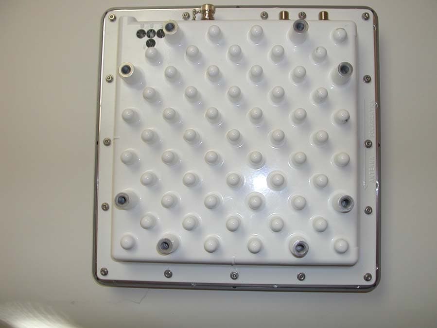
Click to zoom
Application Details
- Equipment Class
- NII - Unlicensed National Information Infrastructure TX
- Date of Grant
- May 06, 2003
- Application Purpose
- Original Equipment
- Date of Application
- May 06, 2003
- Equipment Note
- Wireless Ethernet Bridge
- Frequency Range
- 5745.00000000 - 5805.00000000
- Company
- Cisco Systems Inc
- Country
- United States
Documents & Files
Document Text
Text extracted from the exhibit documents filed with the FCC. Open a document above to read the original.
Users Manual
DRAFT - CISCO CONFIDENTIAL Corporate Headquarters Cisco Systems, Inc. 170 West Tasman Drive San Jose, CA 95134-1706 USA http://www.cisco.com Tel: 408 526-4000 800 553-NETS (6387) Fax: 408 526-4100 Cisco Aironet 1400 Series Wireless Bridge Hardware Installation Guide May, 2003 Customer Order Number: Text Part Number: OL-4072-01 DRAFT - CISCO CONFIDENTIAL THE SPECIFICATIONS AND INFORMATION REGARDING THE PRODUCTS IN THIS MANUAL ARE SUBJECT TO CHANGE WITHOUT NOTICE. ALL STATEMENTS, INFORMATION, AND RECOMMENDATIONS IN THIS MANUAL ARE BELIEVED TO BE ACCURATE BUT ARE PRESENTED WITHOUT WARRANTY OF ANY KIND, EXPRESS OR IMPLIED. USERS MUST TAKE FULL RESPONSIBILITY FOR THEIR APPLICATION OF ANY PRODUCTS. THE SOFTWARE LICENSE AND LIMITED WARRANTY FOR THE ACCOMPANYING PRODUCT ARE SET FORTH IN THE INFORMATION PACKET THAT SHIPPED WITH THE PRODUCT AND ARE INCORPORATED HEREIN BY THIS REFERENCE. IF YOU ARE UNABLE TO LOCATE THE SOFTWARE LICENSE OR LIMITED WARRANTY, CONTACT YOUR CISCO REPRESENTATIVE FOR A COPY. The Cisco implementation of TCP header compression is an adaptation of a program developed by the University of California, Berkeley (UCB) as part of UCB’s public domain version of the UNIX operating system. All rights reserved. Copyright © 1981, Regents of the University of California. NOTWITHSTANDING ANY OTHER WARRANTY HEREIN, ALL DOCUMENT FILES AND SOFTWARE OF THESE SUPPLIERS ARE PROVIDED “AS IS” WITH ALL FAULTS. CISCO AND THE ABOVE-NAMED SUPPLIERS DISCLAIM ALL WARRANTIES, EXPRESSED OR IMPLIED, INCLUDING, WITHOUT LIMITATION, THOSE OF MERCHANTABILITY, FITNESS FOR A PARTICULAR PURPOSE AND NONINFRINGEMENT OR ARISING FROM A COURSE OF DEALING, USAGE, OR TRADE PRACTICE. IN NO EVENT SHALL CISCO OR ITS SUPPLIERS BE LIABLE FOR ANY INDIRECT, SPECIAL, CONSEQUENTIAL, OR INCIDENTAL DAMAGES, INCLUDING, WITHOUT LIMITATION, LOST PROFITS OR LOSS OR DAMAGE TO DATA ARISING OUT OF THE USE OR INABILITY TO USE THIS MANUAL, EVEN IF CISCO OR ITS SUPPLIERS HAVE BEEN ADVISED OF THE POSSIBILITY OF SUCH DAMAGES. Cisco Aironet 1400 Series Wireless Bridge Hardware Installation Guide Copyright ©2003 Cisco Systems, Inc. All rights reserved. CCIP, CCSP, the Cisco Arrow logo, the Cisco Powered Network mark, Cisco Unity, Follow Me Browsing, FormShare, and StackWise are trademarks of Cisco Systems, Inc.; Changing the Way We Work, Live, Play, and Learn, and iQuick Study are service marks of Cisco Systems, Inc.; and Aironet, ASIST, BPX, Catalyst, CCDA, CCDP, CCIE, CCNA, CCNP, Cisco, the Cisco Certified Internetwork Expert logo, Cisco IOS, the Cisco IOS logo, Cisco Press, Cisco Systems, Cisco Systems Capital, the Cisco Systems logo, Empowering the Internet Generation, Enterprise/Solver, EtherChannel, EtherSwitch, Fast Step, GigaStack, Internet Quotient, IOS, IP/TV, iQ Expertise, the iQ logo, iQ Net Readiness Scorecard, LightStream, MGX, MICA, the Networkers logo, Networking Academy, Network Registrar, Pa cke t, PIX, Post-Routing, Pre-Routing, RateMUX, Registrar, ScriptShare, SlideCast, SMARTnet, StrataView Plus, Stratm, SwitchProbe, TeleRouter, The Fastest Way to Increase Your Internet Quotient, TransPath, and VCO are registered trademarks of Cisco Systems, Inc. and/or its affiliates in the U.S. and certain other countries. All other trademarks mentioned in this document or Web site are the property of their respective owners. The use of the word partner does not imply a partnership relationship between Cisco and any other company. (0304R) DRAFT - CISCO CONFIDENTIAL iii Cisco Aironet 1400 Series Wireless Bridge Hardware Installation Guide OL-4072-01 Prefacevii Objectivesvii Audiencevii Organizationvii Conventionsviii Related Publicationsix Obtaining Documentationx Cisco.comx Documentation CD-ROMx Ordering Documentationx Documentation Feedbackxi Obtaining Technical Assistancexi Cisco.comxi Technical Assistance Centerxii Cisco TAC Websitexii Cisco TAC Escalation Centerxii Obtaining Additional Publications and Informationxiii CHAPTER 1Overview1-1 Key Features1-2 Power1-2 External Antenna1-3 Integrated Antenna1-3 Dual-Coax Ethernet Ports1-3 Metal Enclosure1-3 Indicators1-4 Receive Signal Strength Indicator Port1-5 Network Configuration Examples1-5 Point-to-Point Configuration1-5 Port Aggregation or Redundancy Configuration1-5 Point-to-Multipoint Configuration1-6 Bridge Specifications1-6 CHAPTER 2Installation Overview2-1 Warnings2-2 DRAFT - CISCO CONFIDENTIAL Contents iv Cisco Aironet 1400 Series Wireless Bridge Hardware Installation Guide OL-4072-01 Safety Information2-3 FCC Safety Compliance Statement2-3 Safety Precautions2-3 Typical Bridge Installation Components2-4 Installation Guidelines2-5 Site Surveys2-5 Unpacking the Bridge2-5 Package Contents2-6 Before Beginning the Installation2-6 Installation Summary2-8 CHAPTER 3Mounting and Alignment Overview3-1 Mounting the Bridge3-2 Mounting Hardware3-2 Multi-function Mount3-2 Bridge Brackets3-2 Mast Bracket3-3 Bridge LED Indicators3-3 Aligning the Antenna Using LED Indications3-5 Aligning the Antenna Using the RSSI Voltage3-6 CHAPTER 4Configuring the Bridge for the First Time4-1 Before You Start4-2 Resetting the Bridge to Default Settings4-2 Obtaining and Assigning an IP Address4-3 Connecting to the Bridge Locally4-3 Assigning Basic Settings4-4 Default Settings on the Express Setup Page4-8 What To Do Next4-8 Output Power Level4-8 Protecting Your Wireless LAN4-9 Using the IP Setup Utility4-9 Obtaining and Installing IPSU4-9 Using IPSU to Find the Bridge’s IP Address4-10 Using IPSU to Set the Bridge’s IP Address and SSID4-10 Assigning an IP Address Using the CLI4-12 Using a Telnet Session to Access the CLI4-12 DRAFT - CISCO CONFIDENTIAL Contents v Cisco Aironet 1400 Series Wireless Bridge Hardware Installation Guide OL-4072-01 CHAPTER 5Troubleshooting5-1 Checking the LED Indicators5-2 Bridge Installation Mode LED Indications5-3 Bridge Normal Mode LED Indications5-4 Power Injector LED Indicators5-5 Checking Basic Configuration Settings5-7 SSID5-7 Security Settings5-7 Antenna Alignment5-8 Resettin…
Text truncated - open the document above for the full version.
Cover Letter(s)
tel: 650-726-1263 fax: 650-726-1252 email [email protected] Thomas N. Cokenias EMC & Radio Type Approvals Test & Consulting Services for Commercial, Military, International Compliance P.O. Box 1086 El Granada, CA 94018 [email protected] Compliance Certification Services 29 April 2003 561F Monterey Road Morgan Hill, CA 95037 Attention: Mike Kuo Re: Request for confidentiality for portions of certification applications Applicant: Cisco Systems Inc. FCC ID: LDK102047 and LDK102047P Dear Mike, On behalf of my client Cisco Systems Inc., under the provisions of section 0.459 of FCC Rules, I hereby request that the following documents be kept confidential and unavailable for routine inspection; schematics block diagrams operational description Justification; Cisco systems has invested considerable time, effort, and funding in the development of these sophisticated radio products. Routine inspection of these documents would afford competitors and unfair advantage in development of their own similar products. If you have questions or need further information, please don’t hesitate to call. Sincerely, THOMAS N COKENIAS Agent for Cisco Systems Inc.
Cover Letter(s)
From: Tom Cokenias [[email protected]] Sent: Wednesday, May 07, 2003 9:29 AM To: Mike Kuo Subject: Re: FW: Cisco Systems Inc., FCC ID:LDK102047P, AN03T2822 >Hi Mike, The revised user manual is a more recent version and should answer the questions you have about the manual - detailed answers to questions below. > >Notice_content > ------------- >Since the standard antenna connector is used and professional installation >is required per the instruction given in the user manual. There are total >of three types of antenna will be used with this device. By using the Dish >antenna, the output power needs to be reduced to comply bandedge >requirements. Based upon above review, please address the following >questions : > >Question #1: Please provide information to inform the installer which >antenna is for Point to Point and Point to Multipoint operation. ANS 1 See page C2 of the attached manual (pdf document page 82) > >Question #2: If the compliance with the EIRP limit is achieved for various >antennas by adjusting the transmit power at the time of installation. The >installation manual must contain adequate instruction such that the correct >transmit power can be chosen for any antenna being used. Such information >can not be found in the user manual. ANS 2 See page C2 of the attached manual (pdf document page 82) > >Question #3: The FCC ID number listed in the proposed FCC ID label format is >LDK102047 which is for separate TCB application under assessment >no:AN03T2824. Please provide FCC ID label for this application. ANS 3 Label attached > >Question #4: Appendix C and D of user manual contains information which are >not associated with the EUT. Please modify or harmonize the information to >address the regulatory information for this device. The user manual does >not provide information clearly about non co-located requirement for this >device. Please address this issue in the user manual. ANS 4 The current manual is correct. The previous version I sent still had "leftovers" from the document they were modifying, now this irrelevant information has been eliminated. > >Question #5: Please confirm which FCC ID number is for Integral antenna and >which FCC ID number is for bridge with external antenna. ( In the test >report, it refers FCC ID:IDK102047 is for integral antenna but the proposed >FCC ID number indicates otherwise.) ANS 5 FCC ID:IDK102047 is for the integral antenna. FCC ID:IDK102047P has the N connector for the external antennas > >Best Regards > >Mike Kuo >The items indicated above must be submitted before processing can continue >on the above referenced application. Failure to provide the requested >information within 60 days of the original e-mail date may result in >application dismissal and forfeiture of the filing fee. Also, please note >that partial responses increase processing time and should not be submitted. >Any questions about the content of this correspondence should be directed to >the e-mail address listed below the name of the sender.
External Photos
Cisco SystemsUNII Transceiver w/External antennas FCC ID: LDK102047P Product Photographs Cisco SystemsUNII Transceiver w/External antennas FCC ID: LDK102047P
ID Label/Location Info
LABEL APPROVAL FORM NEW | REV CORPORATE I. D.: _________________ DATE: __________ YES | NO PRODUCT MARKETING: _________________ DATE: __________ YES | NO EMISSIONS COMPLIANCE: _________________ DATE: __________ YES | YES PRODUCT SAFETY: _________________ DATE: __________ YES | NO MANAGER, DESIGN ENGINEERING: _________________ DATE: __________ YES | NO MANAGER, MANUFACTURING ENGINEERING: _________________ DATE: __________ YES | YES MANUFACTURING ENGINEER: _________________ DATE: __________ YES | YES PRODUCT COMPLIANCE LABEL _ Silver Characters on Black Background __X__ Black Characters on Silver Background 47-15961-01 REV 01 SCALE: LABEL APPROVAL FORM NEW | REV CORPORATE I. D.: _________________ DATE: __________ YES | NO PRODUCT MARKETING: _________________ DATE: __________ YES | NO EMISSIONS COMPLIANCE: _________________ DATE: __________ YES | YES PRODUCT SAFETY: _________________ DATE: __________ YES | NO MANAGER, DESIGN ENGINEERING: _________________ DATE: __________ YES | NO MANAGER, MANUFACTURING ENGINEERING: _________________ DATE: __________ YES | YES MANUFACTURING ENGINEER: _________________ DATE: __________ YES | YES LABEL APPROVAL FORM NEW | REV CORPORATE I. D.: _________________ DATE: __________ YES | NO PRODUCT MARKETING: _________________ DATE: __________ YES | NO EMISSIONS COMPLIANCE: _________________ DATE: __________ YES | YES PRODUCT SAFETY: _________________ DATE: __________ YES | NO MANAGER, DESIGN ENGINEERING: _________________ DATE: __________ YES | NO MANAGER, MANUFACTURING ENGINEERING: _________________ DATE: __________ YES | YES MANUFACTURING ENGINEER: _________________ DATE: __________ YES | YES
Internal Photos
Cisco SystemsUNII Transceiver w/External antennas FCC ID: LDK102047P Cisco SystemsUNII Transceiver w/External antennas FCC ID: LDK102047P
Parts List/Tune Up Info
3/11/02 External Sector Antenna Specifications A printed version of this document is an uncontrolled copy. Cisco Systems, Inc.Page 1 of 5Company Confidential Document Number: EDCS- 256660 Revision: 1.4 Author: Jack Trollman Manager: Brett Douglas Specification for Pegasus Sector External Antenna Part number: AIR-ANT58G10SSA-N 74-3273-01 Headline This document outlines the technical requirements for the external sector antenna to be used with the Pegasus bridge system. Approvals DepartmentName Approval Date RF Engineering Technical Marketing Marketing Compliance Program Manager Revision History RevDateAuthorComment 1.03/11/02Jack TrollmanInitial Release 1.11/24/03Jack TrollmanInclude new vendor design and out-of-band gains 1.22/12/03Jack TrollmanRevised to new Maxrad round design 1.33/5/03Jack Trollman Revised out of band gains, cross-pol rejection, physical size, color specifications and added radiation pattern. 1.43/20/03Jack TrollmanNew part numbers and radiation patterns 3/11/02 External Sector Antenna Specifications A printed version of this document is an uncontrolled copy. Cisco Systems, Inc.Page 2 of 5Company Confidential 1. Introduction This document describes the basic specifications for the sector antenna to be used with the Pegasus system. 2. Electrical Specifications The electrical specifications for this antenna are summarized in the table below. Typical radiation pattern is shown in Figure 1. Sector Antenna Electrical and Mechanical Specifications ParameterValueUnits Frequency Range5725 – 5825MHz Gain, measured at end of 1.5 Meter cable 5725-5825 MHz 9.5 ± 0.5dBi Maximum Out-of-band Gains: 4.50 - 5.15 GHz (Restricted Band) 5.35-5.46 GHz 7.25-7.75 GHz 8 9 5 dBi Impedance50ohms VSWR1.5:1 max. Azimuth half-power beamwidth (1) 60.0, minimumdegrees Elevation half-power beamwidth (1) 60.0, minimumdegrees Linear polarization options (2) Hor/Vert- Cross-polarization discrimination over boresight ± 25° 18, mindB Sidelobe and Front-to-back ratio level from 120° to 240° (referenced to main lobe peak) 20, mindBc Input RMS power4.0, maxW Approximate Size, (L x W x D) including radome 2.5 x 2.5 x 1.75inches Feed cable1.5, Times LMR- 400 or equivalent Meters RF ConnectorType N-Male Mounting capability (Either Vert. or Horiz. Polarization) Accommodates 1.5 in.to 2.5 in. pipe Elevation adjustmentNone, main beam fixed on horizon Notes: 1. Beamwidth symmetrical. 2. Polarization configurable at installation. Polarization determined by orientation of radiating element. Main beam peak to remain on horizon regardless of polarization setting. 3/11/02 External Sector Antenna Specifications A printed version of this document is an uncontrolled copy. Cisco Systems, Inc.Page 3 of 5Company Confidential Environmental & Regulatory Requirements Temperature Operating-30 o CMin +60 o CMax Storage-40 o CMin +85 o CMax Altitude Operating10000 feetMax Storage16000 feetMax Flammability Antenna and Radome UL94HB Radome Material UV Resistant ABS Plastic or equivalent Humidity0 - 100% RHCondensing Wind Speed Operational100 MPH Survival125 MPH EnclosureNEMA 250-1997Type 4 Lightning ProtectionAll metal parts groundedDC continuity between connector center conductor and ground of 0.1 Ohm or less Metal Parts ColorPantone Cool Gray 2C (GE Cycolac KJB 1000) Plastic Radome ColorCisco Medium GrayCisco Specification 95-5818-01 Cisco labelingSticker on rear panel 3/11/02 External Sector Antenna Specifications A printed version of this document is an uncontrolled copy. Cisco Systems, Inc.Page 4 of 5Company Confidential Figure 1a. Typical E-plane radiation pattern 3/11/02 External Sector Antenna Specifications A printed version of this document is an uncontrolled copy. Cisco Systems, Inc.Page 5 of 5Company Confidential Figure 1b. Typical H-plane radiation pattern 3/11/02 External Sector Antenna Specifications A printed version of this document is an uncontrolled copy. Cisco Systems, Inc.Page 1 of 5Company Confidential Document Number: EDCS-256657 Revision: 1.3 Author: Jack Trollman Manager: Brett Douglas Specification for Pegasus Omnidirectional External Antenna Part number: AIR-ANT58G9VOA-N 74-3272-01 Headline This document outlines the technical requirements for the external omnidirectional antenna to be used with the Pegasus bridge system. Approvals DepartmentName Approval Date RF Engineering Mechanical Engineering Marketing Compliance Program Manager Revision History RevDateAuthorComment 1.03/11/02Jack TrollmanInitial Release 1.12/12/03Jack TrollmanIncorporates new gain, cable type and color 1.23/5/03Jack Trollman Changed color spec to white, corrected Freq. range typo and included typical radiation pattern 1.33/20/03Jack TrollmanNew part numbers and radiation patterns 3/11/02 External Sector Antenna Specifications A printed version of this document is an uncontrolled copy. Cisco Systems, Inc.Page 2 of 5Company Confidential 1. Introduction This document describes the basic specifications for the omnidirectional antenna to be used with the Pegasus system. 2. Electrical Specifications The electrical specifications for this antenna are summarized in the table below. Typical radiation pattern in shown in Figure 1. Omni Antenna Electrical and Mechanical Specifications ParameterValueUnits Frequency Range5725 – 5825MHz Gain, measured at end of 1.5 Meter cable 5725-5825 MHz (1) 9.0, +1.0, -0.5dBi Maximum Out-of-band Gains: 4.5-5.15 GHz 5.35-5.46 GHz 7.25-7.75 GHz 7 7 5 dBi Impedance50ohms VSWR1.5 maximum H-plane half-power beamwidthOmnidirectional E-plane half-power beamwidth6 +/- 0.5degrees PolarizationVertical- Beam TiltNone (on horizon) E-plane sidelobes below beam peak-10.0, minimumdB Input RMS power4.0, maxWatts RF ConnectorType N-Male Mounting capabilityAccommodates 1.5 in.to 2.5 in. pipe Notes: 1. H-plane shall display 360 degree omni pattern of 9.0 dBi +1.0, -0.5 dB including any incidental beam tilt inherent in the design. 3/11/02 External Sector Antenna Specifications A printed version of this document is an uncontrolled…
Text truncated - open the document above for the full version.
RF Exposure Info
Sheet1 Cisco SystemsFCC ID: LDK102047 and LDK102047P RF Hazard Distance CalculationmW/cm2 from Table1: 1.00 Max RF Powe TX Antenna MPE P, dBm G, dBi Safe Distance, cm 24.0 9.5 13.3 24.0 10.0 14.1 24.0 23.0 63.2 22.0 29.5 106.0 Basis of Calculations:E^2/3770 = S, mW/cm2E, V/m = (Pwatts*Ggain*30)^.5/d, metersd = ((Pwatts*G*30)/3770*S))^0.5 Pwatts*Ggain = 10^(PdBm-30+GdBi)/10) NOTE: Installation manual will specify minimum separation distance is 2m even if calculations indicate MPE distance is less Page 1
Test Report
Cisco Systems UNII Transceiver w/ External Antennas FCC ID: LDK102047P page 1 of 42 TEST REPORT FOR CERTIFICATION OF A U-NII TRANSCEIVER Applicant; Cisco Systems, Inc. 170 West Tasman Drive San Jose, CA 95134-1706 FCC ID: LDK102047P Model name: Pegasus Product Description Pegasus is a wireless bridge designed for building to building wireless connectivity. Operating in the 5.8 GHz UNII 3 band, derived from the 802.11a standard, Pegasus delivers up to 54Mbps data rate without special licensing. Pegasus is a self contained unit designed for outdoor installations, providing differing antenna gains as well as coverage patterns and supports both point to point and point to multipoint configurations. Product Block Diagram Product Specifications Transmitter Power: 24 dBm, adjustable in 1 dBm steps Operating Frequency Range: 5745 MHz (Channel 1) 5765 MHz (Channel 2) 5785 MHz (Channel 3) 5805 MHz (Channel 4) Antennas 9.5 dBi omni 10 dBi sector 23 dBi max integral antenna (22.5 dBi typical)* 29.5 dBi max dish (28 dBi typical) Power -48 VDC over Ethernet from power inserter (DC voltage derived from AC adapter) * sold under separate FCC ID: LDK102047. All electronics identical. Cisco Systems UNII Transceiver w/ External Antennas FCC ID: LDK102047P page 2 of 42 Test Procedures and Guidelines 1) ANSI C63.4 15.207, 15.407(b)5, AC line conducted emissions: 0.150 – 30 MHz 15.109, 15.407(b)5, Radiated emissions, below 1 GHz: 30 – 1000 MHz 15.205 TX Radiated emissions, restricted bands: 1 – 40 GHz 2) FCC Public Notice DA 02-2138 dated 30 August 2002 15.407(a)3 Peak power measurement: Method 1 15.407(a)5 Peak power spectral density measurement: Method 2 15.407(b)3,4 Unwanted emissions (band edge psd) Method 2 15.401(c) Emission bandwidth 15.407(a)6 Peak excursion 3) 2002 TCB Instructions: GUIDANCE FOR REVIEWING OF COMPLIANCE SUBMISSIONS FOR UNII DEVICES All testing was performed by me or by qualified EMC test engineers acting under my supervision. Antenna output conducted tests were tested on 25 March 2003 in the RF laboratory at Cisco Building 14 in San Jose, CA. Radiated emissions 1-40GHz were tested on 11 April 2003 at Cisco Building 6 in San Jose, CA. Radiated emissions 30-1000 MHz and AC line conducted emissions were performed 22 October 2002 in Cisco Building P. Testing in Building 14 was performed on 25 March 2003. Testing in Building 6 was performed on 11 April 2003. T.N. Cokenias EMC Consultant and Agent for Cisco Systems Cisco Systems UNII Transceiver w/ External Antennas FCC ID: LDK102047P page 3 of 42 TEST RESULTS 15.401(c) Emission bandwidth Test equipment Agilent 4440A spectrum analyzer 6 dB attenuator coaxial cable (1.3 dB loss at 5.8 GHz) Test Set-up ethernet LAN CAT5 cable dual DC/Ethernet cables Figure 1 Test Procedure From Public Notice DA-02 –2138: - Use a RBW = approximately 1% of the emission bandwidth. - Set the VBW > RBW. Use a peak detector. - Do not use the Max Hold function. Rather, use the view button to capture the emission. - Measure the maximum width of the emission that is 26 dB down from the peak of the emission. - Compare this with the RBW setting of the analyzer. - Readjust RBW and repeat measurement as needed until the RBW/EBW ratio is approximately 1%. Test Results Refer to spectrum analyzer plots below. On the LOW channel, occupied bandwidth measurements were made for three data rates: 6 Mbps 24 Mbps 54 Mbps Measurement results (and theory) indicate occupied bandwidth is independent of data rate for this type of OFDM modulation. Occupied bandwidth for MID and HIGH channel were performed at 24 Mbps only. power injector Radio outdoor unit (ODU) 6 dB Agilent 4440A analyzer AC to 48 VDC AC mains Cisco Systems UNII Transceiver w/ External Antennas FCC ID: LDK102047P page 4 of 42 Occupied Bandwidth, 5745 MHz: LOW channel modulation Rate 6 Mbps Cisco Systems UNII Transceiver w/ External Antennas FCC ID: LDK102047P page 5 of 42 Occupied Bandwidth, 5745 MHz: LOW channel modulation rate 24 Mbps Cisco Systems UNII Transceiver w/ External Antennas FCC ID: LDK102047P page 6 of 42 Occupied Bandwidth, 5745 MHz: LOW channel modulation rate 54 Mbps Cisco Systems UNII Transceiver w/ External Antennas FCC ID: LDK102047P page 7 of 42 Occupied Bandwidth, 5785 MHz: MID channel modulation rate 24 Mbps Cisco Systems UNII Transceiver w/ External Antennas FCC ID: LDK102047P page 8 of 42 Occupied Bandwidth, 5805 MHz: HIGH channel modulation rate 24 Mbps Cisco Systems UNII Transceiver w/ External Antennas FCC ID: LDK102047P page 9 of 42 15.407(a) Peak power measurement Test equipment Agilent 4440A spectrum analyzer 6 dB attenuator coaxial cable (1.3 dB loss at 5.8 GHz) Test Set-up Refer to Figure 1. Test limits 15.407(a) (3) For the band 5.725-5.825 GHz, the peak transmit power over the frequency band operation shall not exceed the lesser of 1 W or 17 dBm + 10log B, where B is the 26-dB emission bandwidth in MHz. In addition, the peak power spectral density shall not exceed 17 dBm in any 1-MHz band. The EUT has a 26 dB BW of 19 MHz. Pmax = 17 + 10log(19) = 29.8 dBm Test Procedure Transmitter was placed in continuous transmit test mode. Transmitter is ON for 180 usec with a 3 usec reset OFF time. Duty cycle correction is 20 log(180/183) = -.14 dB, For reporting purposes, duty cycle correction is considered zero. Sweep time < T (transmit time) because transmitter is transmitting in continuous mode: Method 1 from Public Notice DA-02 –2138: • Set span to encompass the entire emission bandwidth (EBW) of the signal. • Set RBW = 1 MHz. • Set VBW ≥ 3 MHz. • Use sample detector mode if bin width (i.e., span/number of points in spectrum display) < 0.5 RBW. Otherwise use peak detector mode • Use a video trigger with the trigger level set to enable triggering only on full power pulses. Transmitter must operate at full control power for entire sweep of every sweep. If the device transmits continuously, with no off intervals or reduced power intervals, the trigger may be set to “free run”. • Trace average 100 t…
Text truncated - open the document above for the full version.
Contact Information
Applicant
Samuel Kim(Manager, Engineering)
Test Firm
Cisco Systems, Inc.Daisy Poon
Technical Specifications
| # | Rule Parts | Frequency Range | Power Output |
|---|---|---|---|
| 1 | 15E | 5.75 GHz - 5.80 GHz | 275.00 mW |
Other Applications from Cisco Systems Inc

LDKJ98213058
May 25, 2026Wireless Phone
Equipment Class
DSS - Part 15 Spread Spectrum TransmitterLDKIW9165E
Aug 20, 2024Wi-Fi 6E Outdoor Access Point
Equipment Class
6SD - 15E 6 GHz Standard Power Access PointLDKIW9165DH
Aug 05, 2024Wi-Fi 6E Outdoor Access Point
Equipment Class
6SD - 15E 6 GHz Standard Power Access PointLDKUSBC2857
Jul 22, 2024Cisco Headset USB-C Adapter
Equipment Class
DSS - Part 15 Spread Spectrum TransmitterLDKESPRD2922
May 09, 2024UC Phone
Equipment Class
NII - Unlicensed National Information Infrastructure TX