LDK102054E802.11a/b/g access point
Cisco Systems Inc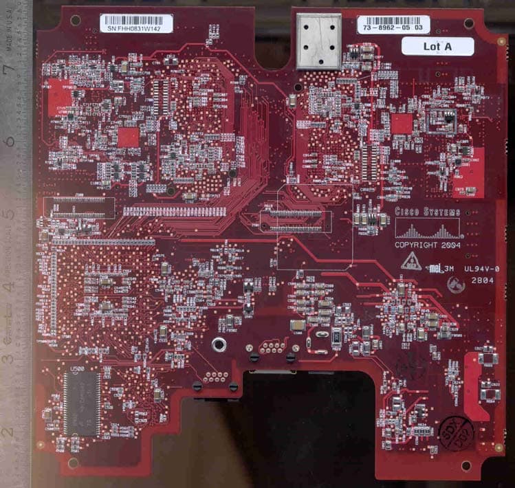
Click to zoom
Application Details
- Equipment Class
- NII - Unlicensed National Information Infrastructure TX
- Date of Grant
- Aug 16, 2006
- Application Purpose
- Original Equipment
- Date of Application
- Mar 01, 2006
- Equipment Note
- 802.11a/b/g access point
- Frequency Range
- 5745.00000000 - 5805.00000000
- Company
- Cisco Systems Inc
- Country
- United States
Documents & Files
Document Text
Text extracted from the exhibit documents filed with the FCC. Open a document above to read the original.
Users Manual
CISCO CONFIDENTIAL - Draft 2 Corporate Headquarters Cisco Systems, Inc. 170 West Tasman Drive San Jose, CA 95134-1706 USA http://www.cisco.com Tel: 408 526-4000 800 553-NETS (6387) Fax: 408 526-4100 Cisco Aironet 1130AG Series Access Point Hardware Installation Guide November 2004 Customer Order Number: Text Part Number: OL-6226-01 CISCO CONFIDENTIAL - Draft 2 THE SPECIFICATIONS AND INFORMATION REGARDING THE PRODUCTS IN THIS MANUAL ARE SUBJECT TO CHANGE WITHOUT NOTICE. ALL STATEMENTS, INFORMATION, AND RECOMMENDATIONS IN THIS MANUAL ARE BELIEVED TO BE ACCURATE BUT ARE PRESENTED WITHOUT WARRANTY OF ANY KIND, EXPRESS OR IMPLIED. USERS MUST TAKE FULL RESPONSIBILITY FOR THEIR APPLICATION OF ANY PRODUCTS. THE SOFTWARE LICENSE AND LIMITED WARRANTY FOR THE ACCOMPANYING PRODUCT ARE SET FORTH IN THE INFORMATION PACKET THAT SHIPPED WITH THE PRODUCT AND ARE INCORPORATED HEREIN BY THIS REFERENCE. IF YOU ARE UNABLE TO LOCATE THE SOFTWARE LICENSE OR LIMITED WARRANTY, CONTACT YOUR CISCO REPRESENTATIVE FOR A COPY. The following information is for FCC compliance of Class A devices: This equipment has been tested and found to comply with the limits for a Class A digital device, pursuant to part 15 of the FCC rules. These limits are designed to provide reasonable protection against harmful interference when the equipment is operated in a commercial environment. This equipment generates, uses, and can radiate radio-frequency energy and, if not installed and used in accordance with the instruction manual, may cause harmful interference to radio communications. Operation of this equipment in a residential area is likely to cause harmful interference, in which case users will be required to correct the interference at their own expense. The following information is for FCC compliance of Class B devices: The equipment described in this manual generates and may radiate radio-frequency energy. If it is not installed in accordance with Cisco’s installation instructions, it may cause interference with radio and television reception. This equipment has been tested and found to comply with the limits for a Class B digital device in accordance with the specifications in part 15 of the FCC rules. These specifications are designed to provide reasonable protection against such interference in a residential installation. However, there is no guarantee that interference will not occur in a particular installation. Modifying the equipment without Cisco’s written authorization may result in the equipment no longer complying with FCC requirements for Class A or Class B digital devices. In that event, your right to use the equipment may be limited by FCC regulations, and you may be required to correct any interference to radio or television communications at your own expense. You can determine whether your equipment is causing interference by turning it off. If the interference stops, it was probably caused by the Cisco equipment or one of its peripheral devices. If the equipment causes interference to radio or television reception, try to correct the interference by using one or more of the following measures: • Turn the television or radio antenna until the interference stops. • Move the equipment to one side or the other of the television or radio. • Move the equipment farther away from the television or radio. • Plug the equipment into an outlet that is on a different circuit from the television or radio. (That is, make certain the equipment and the television or radio are on circuits controlled by different circuit breakers or fuses.) Modifications to this product not authorized by Cisco Systems, Inc. could void the FCC approval and negate your authority to operate the product. The Cisco implementation of TCP header compression is an adaptation of a program developed by the University of California, Berkeley (UCB) as part of UCB’s public domain version of the UNIX operating system. All rights reserved. Copyright © 1981, Regents of the University of California. NOTWITHSTANDING ANY OTHER WARRANTY HEREIN, ALL DOCUMENT FILES AND SOFTWARE OF THESE SUPPLIERS ARE PROVIDED “AS IS” WITH ALL FAULTS. CISCO AND THE ABOVE-NAMED SUPPLIERS DISCLAIM ALL WARRANTIES, EXPRESSED OR IMPLIED, INCLUDING, WITHOUT LIMITATION, THOSE OF MERCHANTABILITY, FITNESS FOR A PARTICULAR PURPOSE AND NONINFRINGEMENT OR ARISING FROM A COURSE OF DEALING, USAGE, OR TRADE PRACTICE. IN NO EVENT SHALL CISCO OR ITS SUPPLIERS BE LIABLE FOR ANY INDIRECT, SPECIAL, CONSEQUENTIAL, OR INCIDENTAL DAMAGES, INCLUDING, WITHOUT LIMITATION, LOST PROFITS OR LOSS OR DAMAGE TO DATA ARISING OUT OF THE USE OR INABILITY TO USE THIS MANUAL, EVEN IF CISCO OR ITS SUPPLIERS HAVE BEEN ADVISED OF THE POSSIBILITY OF SUCH DAMAGES. Cisco Aironet 1130AG Series Access Point Hardware Installation Guide Copyright © 2004 Cisco Systems, Inc. All rights reserved. CCSP, the Cisco Square Bridge logo, Cisco Unity, Follow Me Browsing, FormShare, and StackWise are trademarks of Cisco Systems, Inc.; Changing the Way We Work, Live, Play, and Learn, and iQuick Study are service marks of Cisco Systems, Inc.; and Aironet, ASIST, BPX, Catalyst, CCDA, CCDP, CCIE, CCIP, CCNA, CCNP, Cisco, the Cisco Certified Internetwork Expert logo, Cisco IOS, Cisco Press, Cisco Systems, Cisco Systems Capital, the Cisco Systems logo, Empowering the Internet Generation, Enterprise/Solver, EtherChannel, EtherFast, EtherSwitch, Fast Step, GigaDrive, GigaStack, HomeLink, Internet Quotient, IOS, IP/TV, iQ Expertise, the iQ logo, iQ Net Readiness Scorecard, LightStream, Linksys, MeetingPlace, MGX, the Networkers logo, Networking Academy, Network Registrar, Pa cke t, PIX, Post-Routing, Pre-Routing, ProConnect, RateMUX, Registrar, ScriptShare, SlideCast, SMARTnet, StrataView Plus, SwitchProbe, TeleRouter, The Fastest Way to Increase Your Internet Quotient, TransPath, and VCO are registered trademarks of Cisco Systems, Inc. and/or its affiliates in the United States and certain other countries. All other trademarks mentioned in this docu…
Text truncated - open the document above for the full version.
Cover Letter(s)
Jim Nicholson EMC Compliance Engineer Cisco Systems, Inc. 4125 Highlander Parkway Richfield, OH 44286 Phone: (330) 523-2094 Fax: (330) 523-2002 E-Mail: [email protected] March 2, 2006 Federal Communications Commission Equipment Authorization branch 7435 Oakland Mills Road Columbia, MD 21046 Re: FCC ID: LDK102054E Request for Confidentiality To Whom It May Concern: The following information is to be held confidential pursuant to 47 CFR Part 0 §0.457 and Section 552(b)(4) of the Freedom of Information Act, because the information provided is proprietary and contains trade secrets. If made public, the information might be used to the disadvantage of the Cisco Systems, Inc. in the market place. Block Diagram Schematic Diagrams Hardware Theories of Operation Software Theory of Operation Best Regards, Jim Nicholson EMC Compliance Engineer Cisco Systems, Inc.
Cover Letter(s)
Update to Frequencies : correction of 731 form for LDK102054E 5180 – 5250 MHz 5250 – 5320 MHz 5500 – 5700 MHz 5745- 5805 MHz Transmitter Power of 5500 – 5700 MHz band : 51mW
Cover Letter(s)
Cisco Systems, Inc. 4125 Highlander Parkway Richfield, Ohio 44286 Phone: 330 523-2094 Fax: 330 523-2002 http://www.cisco.com Phone: (330) 523-2094 Fax: (330) 523-2002 E-Mail: [email protected] April 28, 2006 Federal Communications Commission Equipment Authorization Division, Application Processing Branch 7435 Oakland Mills Road Columbia, MD 21046 Re: DFS Test Methodology To Whom It May Concern: The DFS test results submitted in conjunction with this filing were tested to and comply with the Compliance Measurement Procedures for Unlicensed National Information Infrastructure Devices Operating in the 5250-5350 MHz and 5470-5725 MHz Bands Incorporating Dynamic Frequency Selection referenced in Public Notice DA 06-927. Best Regards, Jim Nicholson EMC Compliance Engineer
Cover Letter(s)
Cisco Systems, Inc. 4125 Highlander Parkway Richfield, Ohio 44286 Phone: 330 523-2094 Fax: 330 523-2002 http://www.cisco.com Phone: (330) 523-2094 Fax: (330) 523-2002 E-Mail: [email protected] August 1, 2006 Federal Communications Commission 7435 Oakland Mills Road Columbia MD 21046 Subject: FCC ID: LDK102054E To Whom It May Concern: Cisco Systems would like to request that the current application filed under FCC ID: LDK102054E be granted with two modes of operation as described below: Mode 1 Running in stand-alone “autonomous” mode, where each access point runs independently. In this mode, DFS is supported as well as the channels in the 5470-5725MHz band. Mode 2 Running in managed “Light Weight Access Point Protocol (LWAPP)” mode, where a group of access points are managed by a central switch. In this mode, DFS is not supported at this time, and the channels in the 5470-5725MHz band are disabled. Both DFS and the 5470-5725MHz band will be supported in this mode by the July, 2007 deadline. In both modes, the DFS mechanism is controlled in the access point's IOS software image. Best Regards, Jim Nicholson EMC Compliance Engineer
External Photos
Top with Shields Removed Bottom with Shields Removed Top with Shields Bottom with Shields Top Assembly Bottom Assembly Regulatory Label
ID Label/Location Info
Top with Shields Removed Bottom with Shields Removed Top with Shields Bottom with Shields Top Assembly Bottom Assembly Regulatory Label
Internal Photos
Top with Shields Removed Bottom with Shields Removed Top with Shields Bottom with Shields Top Assembly Bottom Assembly Regulatory Label
Parts List/Tune Up Info
9/08/2004 AIR-AP1131AG Antenna System Design Specification A printed version of this document is an uncontrolled copy. Cisco Systems, Inc. Page 1 of 4 AIR-AP1131AG Antenna System Design Specification 1. Introduction The AIR-AP1131AG access point is a dual band, simultaneous AP supporting 802.11b and 802.11g in the 2.4 GHz band and 802.11a in all the available 5 GHz bands. As such, the product contains a total of 4 antennas. There are two antennas for the 2.4 GHz band and two antennas for the 5 GHz band. The design and operation of these antennas is covered in this document. 3. Antenna Design An inverted-F antenna will be used for both bands. This antenna type is shown in the Figure 1 below. It is formed by bending a monopole antenna down over a ground plane and then driving the resultant antenna away from the grounded end to achieve a 50 Ω driving point impedance. Typically, these antennas are built using a flat plate, rather than a wire, for VSWR bandwidth considerations. 9/08/2004 AIR-AP1131AG Antenna System Design Specification A printed version of this document is an uncontrolled copy. Cisco Systems, Inc. Page 2 of 4 Figure 1. Basic Inverted-F antenna Geometry Figure 4 Photograph of the AIR-AP1131AG Antennas with “Break-away” Support Legs. 9/08/2004 AIR-AP1131AG Antenna System Design Specification A printed version of this document is an uncontrolled copy. Cisco Systems, Inc. Page 3 of 4 4. Antenna Specifications from Measurement Results. 5 GHz Inverted-F Antenna Specifications MinimumTypical MaximumComments Length 13.7 mm (540 mils) Width 4 mm (157 mils) Height 5 mm (197 mils) Material C770 Nickel-Silver Alloy 12 mil thick Mounting Method Surface Mount Antennas have break- away support leg. 2:1 VSWR Bandwidth 5150 MHz - 5825 MHz Covers UNII-1, 2, & 3 Peak Gain 4 dBi 4.5 dBi Peak gain close to +/- 60 degrees from boresight. Front-to-Back Ratio 10 dB This spec is included to help describe the radiation pattern as mostly “away” from the front of the product. 2.4 GHz-to-5 GHz Isolation 30 dB 40 dB 28 dB is the requirement for radio operation Table 1. Summary of 5 GHz Inverted-F Antenna Specs 9/08/2004 AIR-AP1131AG Antenna System Design Specification A printed version of this document is an uncontrolled copy. Cisco Systems, Inc. Page 4 of 4 2.4 GHz Inverted-F Antenna Specifications MinimumTypical MaximumComments Length 25.4 mm (1 inch) Width 9 mm (350 mils) Height 7 mm (0.28 mils) Material C770 Nickel-Silver Alloy 12 mil thick Mounting Method Surface Mount Antennas have break- away support leg. 2:1 VSWR Bandwidth 2400 MHz - 2500 MHz Useable for 802.11 b/g Peak Gain 3 dBi Peak Gain close to +/-45 degrees from boresight. Front-to-Back Ratio 10 dB 5 GHz-to-2.4 GHz Isolation 30 dB 40 dB 30 dB is the requirement for radio operation Table 2. Summary of 2.4 GHz Inverted-F Antenna Specifications
RF Exposure Info
FCC CFR47 PART 15 SUBPART E CERTIFICATION TEST REPORT FOR 802.11 a/b/g ACCESS POINT MODEL NUMBER: AIR-AP1131AG-A-K9 FCC ID: LDK102054E REPORT NUMBER: 06U10108-1, Revision C ISSUE DATE: MARCH 2, 2006 Prepared for CISCO SYSTEMS, INC. 170 WEST TASMAN DRIVE SAN JOSE, CA 95134 Prepared by COMPLIANCE CERTIFICATION SERVICES 561F MONTEREY ROAD, MORGAN HILL, CA 95037, USA TEL: (408) 463-0885 FAX: (408) 463-0888 REPORT NO: 06U10108-1C DATE: MARCH 2, 2006 EUT: 802.11 a/b/g ACCESS POINT FCC ID: LDK102054E Page 2 of 60 COMPLIANCE CERTIFICATION SERVICES DOCUMENT NO: CCSUP4031A 561F MONTEREY ROAD, MORGAN HILL, CA 95037 USA TEL: (408) 463-0885 FAX: (408) 463-0888 This report shall not be reproduced except in full, without the written approval of CCS. Revision History Rev. Revisions Revised By A Initial Issue DG B Corrected typo in model number DG C Corrected FCC ID per customer request DG REPORT NO: 06U10108-1C DATE: MARCH 2, 2006 EUT: 802.11 a/b/g ACCESS POINT FCC ID: LDK102054E Page 3 of 60 COMPLIANCE CERTIFICATION SERVICES DOCUMENT NO: CCSUP4031A 561F MONTEREY ROAD, MORGAN HILL, CA 95037 USA TEL: (408) 463-0885 FAX: (408) 463-0888 This report shall not be reproduced except in full, without the written approval of CCS. TABLE OF CONTENTS 1. TEST RESULT CERTIFICATION.................................................................................................. 4 2. TEST METHODOLOGY .................................................................................................................. 5 3. FACILITIES AND ACCREDITATION .......................................................................................... 5 4. EUT DESCRIPTION.......................................................................................................................... 6 5. CALIBRATION AND UNCERTAINTY.......................................................................................... 7 5.1. MEASURING INSTRUMENT CALIBRATION ............................................................................. 7 5.2. MEASUREMENT UNCERTAINTY ............................................................................................... 7 5.3. TEST AND MEASUREMENT EQUIPMENT................................................................................ 7 6. SETUP OF EQUIPMENT UNDER TEST ....................................................................................... 9 7. APPLICABLE LIMITS AND TEST RESULTS ........................................................................... 11 7.1. CHANNEL TESTS FOR THE 5470 TO 5725 MHz BAND ......................................................... 11 7.1.1. EMISSION BANDWIDTH ................................................................................................ 11 7.1.2. PEAK POWER ................................................................................................................... 15 7.1.3. MAXIMUM PERMISSIBLE EXPOSURE ........................................................................ 20 7.1.4. CO-LOCATED MAXIMUM PERMISSIBLE EXPOSURE ............................................. 23 7.1.5. AVERAGE POWER........................................................................................................... 26 7.1.6. PEAK POWER SPECTRAL DENSITY ............................................................................ 27 7.1.7. PEAK EXCURSION .......................................................................................................... 31 7.1.8. CONDUCTED SPURIOUS EMISSIONS.......................................................................... 35 7.2. RADIATED EMISSIONS.............................................................................................................39 7.2.1. LIMITS AND PROCEDURES........................................................................................... 39 7.2.2. TRANSMITTER RADIATED EMISSIONS ABOVE 1 GHZ FOR 5470 MHz TO 5725 MHz 42 7.2.3. WORST-CASE BELOW 1 GHz ........................................................................................ 51 7.3. POWERLINE CONDUCTED EMISSIONS ................................................................................ 53 8. SETUP PHOTOS .............................................................................................................................. 56 REPORT NO: 06U10108-1C DATE: MARCH 2, 2006 EUT: 802.11 a/b/g ACCESS POINT FCC ID: LDK102054E Page 4 of 60 COMPLIANCE CERTIFICATION SERVICES DOCUMENT NO: CCSUP4031A 561F MONTEREY ROAD, MORGAN HILL, CA 95037 USA TEL: (408) 463-0885 FAX: (408) 463-0888 This report shall not be reproduced except in full, without the written approval of CCS. 1. TEST RESULT CERTIFICATION COMPANY NAME: CISCO SYSTEMS, INC. 170 WEST TASMAN DRIVE SAN JOSE, CA 95134 EUT DESCRIPTION: 802.11 a/b/g Access Point MODEL: AIR-AP1131AG-A-K9 DATE TESTED: JUNE 30 – JULY 29, 2004 APPLICABLE STANDARDS STANDARD TEST RESULTS FCC PART 15 SUBPART E NO NON-COMPLIANCE NOTED Compliance Certification Services, Inc. tested the above equipment in accordance with the requirements set forth in the above standards. The test results show that the equipment tested is capable of demonstrating compliance with the requirements as documented in this report. Note: The results documented in this report apply only to the tested sample, under the conditions and modes of operation as described herein. This document may not be altered or revised in any way unless done so by Compliance Certification Services and all revisions are duly noted in the revisions section. Any alteration of this document not carried out by Compliance Certification Services will constitute fraud and shall nullify the document. No part of this report may be used to claim product certification, approval, or endorsement by NVLAP, NIST, or any government agency. Approved & Released For CCS By: Tested By: DAVID GARCIA YAN ZHENG ENGINEERING MANAGER EMC ENGINEER COMPLIANCE CERTIFICATION SERVICES COMPLIANCE CERTIFICATION SERVICES REPORT NO: 06U10108-1C DATE: MARCH 2, 200…
Text truncated - open the document above for the full version.
RF Exposure Info
REPORT NO: 04U2603-2 DATE: AUGUST 30, 2004 EUT: 802.11 a/b/g ACCESS POINT FCC ID: LDK102054 COMPLIANCE CERTIFICATION SERVICES DOCUMENT NO: CCSUP4031A 561F MONTEREY ROAD, MORGAN HILL, CA 95037 USA TEL: (408) 463-0885 FAX: (408) 463-0888 This report shall not be reproduced except in full, without the written approval of CCS. This document may be altered or revised by Compliance Certification Services personnel only, and shall be noted in the revision section of the document. SCOPE OF DOCUMENT Compliance Certification Services hereby gives written permission for the following partial reproduction and extract of the MPE sections from report number 04U2603-2. MIKE HECKROTTE ENGINEERING MANAGER COMPLIANCE CERTIFICATION SERVICES REPORT NO: 04U2603-2 DATE: AUGUST 30, 2004 EUT: 802.11 a/b/g ACCESS POINT FCC ID: LDK102054 COMPLIANCE CERTIFICATION SERVICES DOCUMENT NO: CCSUP4031A 561F MONTEREY ROAD, MORGAN HILL, CA 95037 USA TEL: (408) 463-0885 FAX: (408) 463-0888 This report shall not be reproduced except in full, without the written approval of CCS. This document may be altered or revised by Compliance Certification Services personnel only, and shall be noted in the revision section of the document. 7.1.3 MAXIMUM PERMISSIBLE EXPOSURE LIMITS §1.1310 The criteria listed in Table 1 shall be used to evaluate the environmental impact of human exposure to radio-frequency (RF) radiation as specified in §1.1307(b), except in the case of portable devices which shall be evaluated according to the provisions of §2.1093 of this chapter. REPORT NO: 04U2603-2 DATE: AUGUST 30, 2004 EUT: 802.11 a/b/g ACCESS POINT FCC ID: LDK102054 COMPLIANCE CERTIFICATION SERVICES DOCUMENT NO: CCSUP4031A 561F MONTEREY ROAD, MORGAN HILL, CA 95037 USA TEL: (408) 463-0885 FAX: (408) 463-0888 This report shall not be reproduced except in full, without the written approval of CCS. This document may be altered or revised by Compliance Certification Services personnel only, and shall be noted in the revision section of the document. CALCULATIONS Given E = √ (30 * P * G) / d and S = E ^ 2 / 3770 where E = Field Strength in Volts/meter P = Power in Watts G = Numeric antenna gain d = Distance in meters S = Power Density in milliwatts/square centimeter Combining equations and rearranging the terms to express the distance as a function of the remaining variables yields: d = √ ((30 * P * G) / (3770 * S)) Changing to units of Power to mW and Distance to cm, using: P (mW) = P (W) / 1000 and d (cm) =100 * d (m) yields d = 100 * √ ((30 * (P / 1000) * G) / (3770 * S)) d = 0.282 * √ (P * G / S) where d = distance in cm P = Power in mW G = Numeric antenna gain S = Power Density in mW/cm^2 Substituting the logarithmic form of power and gain using: P (mW) = 10 ^ (P (dBm) / 10) and G (numeric) = 10 ^ (G (dBi) / 10) yields d = 0.282 * 10 ^ ((P + G) / 20) / √ S Equation (1) where d = MPE distance in cm P = Power in dBm G = Antenna Gain in dBi S = Power Density Limit in mW/cm^2 Equation (1) and the measured peak power is used to calculate the MPE distance. REPORT NO: 04U2603-2 DATE: AUGUST 30, 2004 EUT: 802.11 a/b/g ACCESS POINT FCC ID: LDK102054 COMPLIANCE CERTIFICATION SERVICES DOCUMENT NO: CCSUP4031A 561F MONTEREY ROAD, MORGAN HILL, CA 95037 USA TEL: (408) 463-0885 FAX: (408) 463-0888 This report shall not be reproduced except in full, without the written approval of CCS. This document may be altered or revised by Compliance Certification Services personnel only, and shall be noted in the revision section of the document. LIMITS From §1.1310 Table 1 (B), S = 1.0 mW/cm^2 RESULTS No non-compliance noted: NOTE: For mobile or fixed location transmitters, the minimum separation distance is 20 cm, even if calculations indicate that the MPE distance would be less. ModePower DensityOutputAntennaMPE LimitPowerGainDistance (mW/cm^2)(dBm)(dBi)(cm) 802.11a1.017.314.003.28 REPORT NO: 04U2603-2 DATE: AUGUST 30, 2004 EUT: 802.11 a/b/g ACCESS POINT FCC ID: LDK102054 COMPLIANCE CERTIFICATION SERVICES DOCUMENT NO: CCSUP4031A 561F MONTEREY ROAD, MORGAN HILL, CA 95037 USA TEL: (408) 463-0885 FAX: (408) 463-0888 This report shall not be reproduced except in full, without the written approval of CCS. This document may be altered or revised by Compliance Certification Services personnel only, and shall be noted in the revision section of the document. 7.2.3 MAXIMUM PERMISSIBLE EXPOSURE LIMITS §1.1310 The criteria listed in Table 1 shall be used to evaluate the environmental impact of human exposure to radio-frequency (RF) radiation as specified in §1.1307(b), except in the case of portable devices which shall be evaluated according to the provisions of §2.1093 of this chapter. REPORT NO: 04U2603-2 DATE: AUGUST 30, 2004 EUT: 802.11 a/b/g ACCESS POINT FCC ID: LDK102054 COMPLIANCE CERTIFICATION SERVICES DOCUMENT NO: CCSUP4031A 561F MONTEREY ROAD, MORGAN HILL, CA 95037 USA TEL: (408) 463-0885 FAX: (408) 463-0888 This report shall not be reproduced except in full, without the written approval of CCS. This document may be altered or revised by Compliance Certification Services personnel only, and shall be noted in the revision section of the document. CALCULATIONS Given E = √ (30 * P * G) / d and S = E ^ 2 / 3770 where E = Field Strength in Volts/meter P = Power in Watts G = Numeric antenna gain d = Distance in meters S = Power Density in milliwatts/square centimeter Combining equations and rearranging the terms to express the distance as a function of the remaining variables yields: d = √ ((30 * P * G) / (3770 * S)) Changing to units of Power to mW and Distance to cm, using: P (mW) = P (W) / 1000 and d (cm) =100 * d (m) yields d = 100 * √ ((30 * (P / 1000) * G) / (3770 * S)) d = 0.282 * √ (P * G / S) where d = distance in cm P = Power in mW G = Numeric antenna gain S = Power Density in mW/cm^2 Substituting the logarithmic form of power and gain using: P (mW) = 10 ^ (P (dBm) / 10) and G (numeric) = 10 ^ (G (dBi) / 10) yields d = 0.282 * 10 ^ ((P + G) / 20) / √ S Equation (1) wher…
Text truncated - open the document above for the full version.
RF Exposure Info
REPORT NO: 06U10108-1C DATE: MARCH 2, 2006 EUT: 802.11 a/b/g ACCESS POINT FCC ID: LDK102054E COMPLIANCE CERTIFICATION SERVICES DOCUMENT NO: CCSUP4031A 561F MONTEREY ROAD, MORGAN HILL, CA 95037 USA TEL: (408) 463-0885 FAX: (408) 463-0888 This report shall not be reproduced except in full, without the written approval of CCS. SCOPE OF DOCUMENT Compliance Certification Services hereby gives written permission for the following partial reproduction and extract of the MPE sections from report number 06U10108-1C. MIKE HECKROTTE ENGINEERING MANAGER COMPLIANCE CERTIFICATION SERVICES REPORT NO: 06U10108-1C DATE: MARCH 2, 2006 EUT: 802.11 a/b/g ACCESS POINT FCC ID: LDK102054E COMPLIANCE CERTIFICATION SERVICES DOCUMENT NO: CCSUP4031A 561F MONTEREY ROAD, MORGAN HILL, CA 95037 USA TEL: (408) 463-0885 FAX: (408) 463-0888 This report shall not be reproduced except in full, without the written approval of CCS. 7.1.3 MAXIMUM PERMISSIBLE EXPOSURE LIMITS §1.1310 The criteria listed in Table 1 shall be used to evaluate the environmental impact of human exposure to radio-frequency (RF) radiation as specified in §1.1307(b), except in the case of portable devices which shall be evaluated according to the provisions of §2.1093 of this chapter. REPORT NO: 06U10108-1C DATE: MARCH 2, 2006 EUT: 802.11 a/b/g ACCESS POINT FCC ID: LDK102054E COMPLIANCE CERTIFICATION SERVICES DOCUMENT NO: CCSUP4031A 561F MONTEREY ROAD, MORGAN HILL, CA 95037 USA TEL: (408) 463-0885 FAX: (408) 463-0888 This report shall not be reproduced except in full, without the written approval of CCS. CALCULATIONS Given E = √ (30 * P * G) / d and S = E ^ 2 / 3770 where E = Field Strength in Volts/meter P = Power in Watts G = Numeric antenna gain d = Distance in meters S = Power Density in milliwatts/square centimeter Combining equations and rearranging the terms to express the distance as a function of the remaining variables yields: d = √ ((30 * P * G) / (3770 * S)) Changing to units of Power to mW and Distance to cm, using: P (mW) = P (W) / 1000 and d (cm) =100 * d (m) yields d = 100 * √ ((30 * (P / 1000) * G) / (3770 * S)) d = 0.282 * √ (P * G / S) where d = distance in cm P = Power in mW G = Numeric antenna gain S = Power Density in mW/cm^2 Substituting the logarithmic form of power and gain using: P (mW) = 10 ^ (P (dBm) / 10) and G (numeric) = 10 ^ (G (dBi) / 10) yields d = 0.282 * 10 ^ ((P + G) / 20) / √ S where d = MPE distance in cm P = Power in dBm G = Antenna Gain in dBi S = Power Density Limit in mW/cm^2 Rearranging terms to calculate the power density at a specific distance yields S = 0.0795 * 10 ^ ((P + G) / 10) / (d^2) REPORT NO: 06U10108-1C DATE: MARCH 2, 2006 EUT: 802.11 a/b/g ACCESS POINT FCC ID: LDK102054E COMPLIANCE CERTIFICATION SERVICES DOCUMENT NO: CCSUP4031A 561F MONTEREY ROAD, MORGAN HILL, CA 95037 USA TEL: (408) 463-0885 FAX: (408) 463-0888 This report shall not be reproduced except in full, without the written approval of CCS. LIMITS From §1.1310 Table 1 (B), the maximum value of S = 1.0 mW/cm^2 RESULTS No non-compliance noted: (MPE distance equals 20 cm) NOTE: For mobile or fixed location transmitters, the minimum separation distance is 20 cm, even if calculations indicate that the MPE distance would be less. ModeMPEOutputAntennaPower DistancePowerGainDensity (cm)(dBm)(dBi)(mW/cm^2) 802.11a20.016.444.000.02 REPORT NO: 06U10108-1C DATE: MARCH 2, 2006 EUT: 802.11 a/b/g ACCESS POINT FCC ID: LDK102054E COMPLIANCE CERTIFICATION SERVICES DOCUMENT NO: CCSUP4031A 561F MONTEREY ROAD, MORGAN HILL, CA 95037 USA TEL: (408) 463-0885 FAX: (408) 463-0888 This report shall not be reproduced except in full, without the written approval of CCS. 7.1.4 CO-LOCATED MAXIMUM PERMISSIBLE EXPOSURE LIMITS §1.1310 The criteria listed in Table 1 shall be used to evaluate the environmental impact of human exposure to radio-frequency (RF) radiation as specified in §1.1307(b), except in the case of portable devices which shall be evaluated according to the provisions of §2.1093 of this chapter. REPORT NO: 06U10108-1C DATE: MARCH 2, 2006 EUT: 802.11 a/b/g ACCESS POINT FCC ID: LDK102054E COMPLIANCE CERTIFICATION SERVICES DOCUMENT NO: CCSUP4031A 561F MONTEREY ROAD, MORGAN HILL, CA 95037 USA TEL: (408) 463-0885 FAX: (408) 463-0888 This report shall not be reproduced except in full, without the written approval of CCS. CALCULATIONS Given E = √ (30 * P * G) / d and S = E ^ 2 / 3770 where E = Field Strength in Volts/meter P = Power in Watts G = Numeric antenna gain d = Distance in meters S = Power Density in milliwatts/square centimeter Combining equations and rearranging the terms to express the distance as a function of the remaining variables yields: d = √ ((30 * P * G) / (3770 * S)) Changing to units of Power to mW and Distance to cm, using: P (mW) = P (W) / 1000 and d (cm) =100 * d (m) yields d = 100 * √ ((30 * (P / 1000) * G) / (3770 * S)) d = 0.282 * √ (P * G / S) where d = distance in cm P = Power in mW G = Numeric antenna gain S = Power Density in mW/cm^2 For multiple colocated transmitters operating simultaneously the total power density can be calculated by summing the Power * Gain product of each transmitter. yields d = 0.282 * √ ((P1 * G1) + (P2 * G2) + ... + (Pn * Gn)) / S) where d = distance in cm Pk = Power in mW of the kth transmitter Gk = Numeric antenna gain of the kth transmitter S = Power Density in mW/cm^2 Rearranging terms to calculate the power density at a specific distance yields S = 0.0795 * 10 ^ (((P1 * G1) + (P2 * G2) + ... + (Pn * Gn)) / 10) / (d^2) REPORT NO: 06U10108-1C DATE: MARCH 2, 2006 EUT: 802.11 a/b/g ACCESS POINT FCC ID: LDK102054E COMPLIANCE CERTIFICATION SERVICES DOCUMENT NO: CCSUP4031A 561F MONTEREY ROAD, MORGAN HILL, CA 95037 USA TEL: (408) 463-0885 FAX: (408) 463-0888 This report shall not be reproduced except in full…
Text truncated - open the document above for the full version.
Contact Information
Applicant
Samuel Kim(Manager, Engineering)
Technical Contact
Cisco SystemsJim Nicholson
[email protected]330-523-2094
4125 Highlander Parkway · Richfield, Ohio · United States
Test Firm
Cisco Systems, Inc.Dave Wilson
Technical Specifications
| # | Rule Parts | Frequency Range | Power Output |
|---|---|---|---|
| 4 | 15E | 5.75 GHz - 5.80 GHz | 42.00 mW |
Other Applications from Cisco Systems Inc

LDKJ98213058
May 25, 2026Wireless Phone
Equipment Class
DSS - Part 15 Spread Spectrum TransmitterLDKIW9165E
Aug 20, 2024Wi-Fi 6E Outdoor Access Point
Equipment Class
6SD - 15E 6 GHz Standard Power Access PointLDKIW9165DH
Aug 05, 2024Wi-Fi 6E Outdoor Access Point
Equipment Class
6SD - 15E 6 GHz Standard Power Access PointLDKUSBC2857
Jul 22, 2024Cisco Headset USB-C Adapter
Equipment Class
DSS - Part 15 Spread Spectrum TransmitterLDKESPRD2922
May 09, 2024UC Phone
Equipment Class
NII - Unlicensed National Information Infrastructure TX