LDK102056802.11a/b/g Access Point
Cisco Systems Inc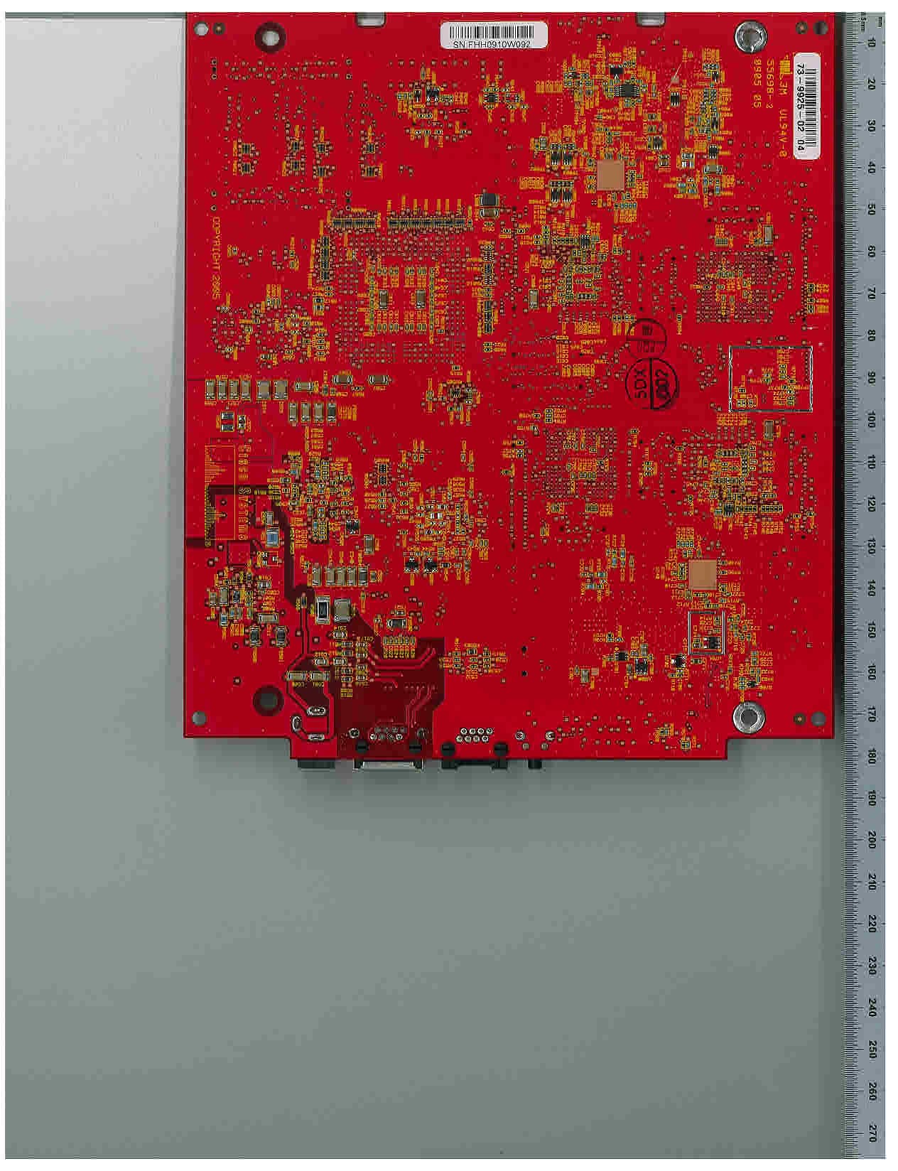
Click to zoom
Application Details
- Equipment Class
- NII - Unlicensed National Information Infrastructure TX
- Date of Grant
- Aug 30, 2005
- Application Purpose
- Original Equipment
- Date of Application
- May 16, 2005
- Equipment Note
- 802.11a/b/g Access Point
- Frequency Range
- 5745.00000000 - 5805.00000000
- Company
- Cisco Systems Inc
- Country
- United States
Documents & Files
Document Text
Text extracted from the exhibit documents filed with the FCC. Open a document above to read the original.
Users Manual
Draft 1A - CISCO CONFIDENTIAL Corporate Headquarters Cisco Systems, Inc. 170 West Tasman Drive San Jose, CA 95134-1706 USA http://www.cisco.com Tel: 408 526-4000 800 553-NETS (6387) Fax: 408 526-4100 Cisco Aironet 1240AG Series Access Point Hardware Installation Guide May 2005 Text Part Number: OL-7293-01 Draft 1A - CISCO CONFIDENTIAL THE SPECIFICATIONS AND INFORMATION REGARDING THE PRODUCTS IN THIS MANUAL ARE SUBJECT TO CHANGE WITHOUT NOTICE. ALL STATEMENTS, INFORMATION, AND RECOMMENDATIONS IN THIS MANUAL ARE BELIEVED TO BE ACCURATE BUT ARE PRESENTED WITHOUT WARRANTY OF ANY KIND, EXPRESS OR IMPLIED. USERS MUST TAKE FULL RESPONSIBILITY FOR THEIR APPLICATION OF ANY PRODUCTS. THE SOFTWARE LICENSE AND LIMITED WARRANTY FOR THE ACCOMPANYING PRODUCT ARE SET FORTH IN THE INFORMATION PACKET THAT SHIPPED WITH THE PRODUCT AND ARE INCORPORATED HEREIN BY THIS REFERENCE. IF YOU ARE UNABLE TO LOCATE THE SOFTWARE LICENSE OR LIMITED WARRANTY, CONTACT YOUR CISCO REPRESENTATIVE FOR A COPY. The following information is for FCC compliance of Class A devices: This equipment has been tested and found to comply with the limits for a Class A digital device, pursuant to part 15 of the FCC rules. These limits are designed to provide reasonable protection against harmful interference when the equipment is operated in a commercial environment. This equipment generates, uses, and can radiate radio-frequency energy and, if not installed and used in accordance with the instruction manual, may cause harmful interference to radio communications. Operation of this equipment in a residential area is likely to cause harmful interference, in which case users will be required to correct the interference at their own expense. The following information is for FCC compliance of Class B devices: The equipment described in this manual generates and may radiate radio-frequency energy. If it is not installed in accordance with Cisco’s installation instructions, it may cause interference with radio and television reception. This equipment has been tested and found to comply with the limits for a Class B digital device in accordance with the specifications in part 15 of the FCC rules. These specifications are designed to provide reasonable protection against such interference in a residential installation. However, there is no guarantee that interference will not occur in a particular installation. Modifying the equipment without Cisco’s written authorization may result in the equipment no longer complying with FCC requirements for Class A or Class B digital devices. In that event, your right to use the equipment may be limited by FCC regulations, and you may be required to correct any interference to radio or television communications at your own expense. You can determine whether your equipment is causing interference by turning it off. If the interference stops, it was probably caused by the Cisco equipment or one of its peripheral devices. If the equipment causes interference to radio or television reception, try to correct the interference by using one or more of the following measures: • Turn the television or radio antenna until the interference stops. • Move the equipment to one side or the other of the television or radio. • Move the equipment farther away from the television or radio. • Plug the equipment into an outlet that is on a different circuit from the television or radio. (That is, make certain the equipment and the television or radio are on circuits controlled by different circuit breakers or fuses.) Modifications to this product not authorized by Cisco Systems, Inc. could void the FCC approval and negate your authority to operate the product. The Cisco implementation of TCP header compression is an adaptation of a program developed by the University of California, Berkeley (UCB) as part of UCB’s public domain version of the UNIX operating system. All rights reserved. Copyright © 1981, Regents of the University of California. NOTWITHSTANDING ANY OTHER WARRANTY HEREIN, ALL DOCUMENT FILES AND SOFTWARE OF THESE SUPPLIERS ARE PROVIDED “AS IS” WITH ALL FAULTS. CISCO AND THE ABOVE-NAMED SUPPLIERS DISCLAIM ALL WARRANTIES, EXPRESSED OR IMPLIED, INCLUDING, WITHOUT LIMITATION, THOSE OF MERCHANTABILITY, FITNESS FOR A PARTICULAR PURPOSE AND NONINFRINGEMENT OR ARISING FROM A COURSE OF DEALING, USAGE, OR TRADE PRACTICE. IN NO EVENT SHALL CISCO OR ITS SUPPLIERS BE LIABLE FOR ANY INDIRECT, SPECIAL, CONSEQUENTIAL, OR INCIDENTAL DAMAGES, INCLUDING, WITHOUT LIMITATION, LOST PROFITS OR LOSS OR DAMAGE TO DATA ARISING OUT OF THE USE OR INABILITY TO USE THIS MANUAL, EVEN IF CISCO OR ITS SUPPLIERS HAVE BEEN ADVISED OF THE POSSIBILITY OF SUCH DAMAGES. Cisco Aironet 1240AG Series Access Point Hardware Installation Guide Copyright © 2005 Cisco Systems, Inc. All rights reserved. CCSP, CCVP, the Cisco Square Bridge logo, Follow Me Browsing, and StackWise are trademarks of Cisco Systems, Inc.; Changing the Way We Work, Live, Play, and Learn, and iQuick Study are service marks of Cisco Systems, Inc.; and Access Registrar, Aironet, ASIST, BPX, Catalyst, CCDA, CCDP, CCIE, CCIP, CCNA, CCNP, Cisco, the Cisco Certified Internetwork Expert logo, Cisco IOS, Cisco Press, Cisco Systems, Cisco Systems Capital, the Cisco Systems logo, Cisco Unity, Empowering the Internet Generation, Enterprise/Solver, EtherChannel, EtherFast, EtherSwitch, Fast Step, FormShare, GigaDrive, GigaStack, HomeLink, Internet Quotient, IOS, IP/TV, iQ Expertise, the iQ logo, iQ Net Readiness Scorecard, LightStream, Linksys, MeetingPlace, MGX, the Networkers logo, Networking Academy, Network Registrar, Packet, PIX, Post-Routing, Pre-Routing, ProConnect, RateMUX, ScriptShare, SlideCast, SMARTnet, StrataView Plus, TeleRouter, The Fastest Way to Increase Your Internet Quotient, and TransPath are registered trademarks of Cisco Systems, Inc. and/or its affiliates in the United States and certain other countries. All other trademarks mentioned in this document or Website are the property …
Text truncated - open the document above for the full version.
Attestation Statements
Response to Questions Posed by Mr. Andrew Leimer, FCC Application Processing Branch July 6, 2005 Re: FCC ID: LDK102056 Applicant: Cisco Systems, Inc. Correspondence Reference Number 29134 731 Confirmation Numbers EA458806 and EA88290 1) Submit an internal photos exhibit. You can cut/paste them from the external photos exhibit. A file is required or the system will lock out the Grant feature. An internal photos exhibit has been uploaded. 2) Explain how this device meets the unique antenna connector requirements of Section 15.203. This device uses reverse polarity TNC connectors for external antenna connections to comply with the unique antenna connector requirement of 15.203. 3) Submit a new Theory of Hardware Operation file. Figure 1 is unreadable. Please view the file before resubmission. A new Hardware Theory of Operation has been uploaded. 3) Submit an MPE exhibit the RF Exposure exhibit. Once again, you can cut/paste it from the Test Report exhibit. An RF exposure exhibit has been uploaded. 4) “Submit a letter explaining how this device meets the definition and requirements for SDR.” 47 U.S.C. Section 2.1 Terms and Definitions. * * * * * (c) * * * Software Defined Radio. A radio that includes a transmitter in which the operating parameters of frequency range, modulation type or maximum output power (either radiated or conducted), or the circumstances under which the transmitter operates in accordance with Commission rules, can be altered by making a change in software without making any changes to hardware components that affect the radio frequency emissions. The hardware and firmware architecture allows alteration of the frequency range and output power in a conducted sense under software control. The “circumstances under which the transmitter operates in accordance with Commission rules,” in particular, will apply to future software releases enacting approved DFS operation in the 5.47-5.725 GHz band. This and any other future operational changes will be implemented completely in software without any hardware component changes “that affect the radio frequency emissions.” The access point has been designed and characterized in advance for compliant operation in the 5.47-5.725 GHz band. Said operation will be made available to customers by Cisco’s future release and controlled distribution of software updates under the allowance of a Class III permissive change. 2.944 Software Defined radios. (a) Manufacturers must take steps to ensure that only software that has been approved with a software defined radio can be loaded into the radio. The software must not allow the user to operate the transmitter with operating frequencies, output power, modulation types or other radio frequency parameters outside those that were approved. Manufacturers may use means including, but not limited to the use of a private network that allows only authenticated users to download software, electronic signatures in software or coding in hardware that is decoded by software to verify that new software can be legally loaded into a device to meet these requirements and must describe the methods in their application for equipment authorization. Future software releases which allow new operational parameters, particularly approved operation in the 5.47-5.725 GHz band, will be released in a conventional manner to Cisco customers. New units shipping from the factory, as well as units already in the field, have unalterable firmware configurations which define the radio’s regulatory domain. These configurations will interact with the new software to restrain the operation within the original regulatory domain. (b) Any radio in which the software is designed or expected to be modified by a party other than the manufacturer and would affect the operating parameters of frequency range, modulation type or maximum output power (either radiated or conducted), or the circumstances under which the transmitter operates in accordance with Commission rules, must comply with the requirements in paragraph (a) of this section and must be certified as a software defined radio. Cisco neither has provided for or expects any third party alteration of software. This includes software installed on existing units as well as future software updates. (b) Applications for certification of software defined radios must include a high level operational description or flow diagram of the software that controls the radio frequency operating parameters. Such descriptions and diagrams are attached to the original filing. See attachments Cisco AP Software Theory of Operation. 2.1043 Changes to certificated equipment. * * * * * (b) * * * (3) A Class III permissive change includes modifications to the software of a software defined radio transmitter that change the frequency range, modulation type or maximum output power (either radiated or conducted) outside the parameters previously approved, or that change the circumstances under which the transmitter operates in accordance with Commission rules. When a Class III permissive change is made, the grantee shall supply the Commission with a description of the changes and test results showing that the equipment complies with the applicable rules with the new software loaded, including compliance with the applicable RF exposure requirements. The modified software shall not be loaded into the equipment, and the equipment shall not be marketed with the modified software under the existing grant of certification, prior to acknowledgement by the Commission that the change is acceptable. Class III changes are permitted only for equipment in which no Class II changes have been made from the originally approved device. NOTE TO PARAGRAPH (b)(3): Any software change that degrades spurious and out-of-band emissions previously reported to the Commission at the time of initial certification would be considered a change in frequency or modulation and would require a Class III permissive change or new equipment autho…
Text truncated - open the document above for the full version.
Cover Letter(s)
Cisco Systems, Inc. 4125 Highlander Parkway Richfield, Ohio 44286 Phone: 330 523-2094 Fax: 330 523-2002 http://www.cisco.com Phone: (330) 523-2094 Fax: (330) 523-2002 E-Mail: [email protected] July 20, 2005 Federal Communications Commission 7435 Oakland Mills Road Columbia MD 21046 Subject: Grant Deferral Date Change FCC ID: LDK102056 To Whom It May Concern: Please change the grant deferral date for FCC ID: LDK102056 to September 13, 2005. This date represents a change to the originally requested August 1, 2005 deferral date. Best Regards, Jim Nicholson EMC Compliance Engineer
Cover Letter(s)
Cisco Systems, Inc. 4125 Highlander Parkway Richfield, Ohio 44286 Phone: 330 523-2094 Fax: 330 523-2002 http://www.cisco.com Phone: (330) 523-2094 Fax: (330) 523-2002 E-Mail: [email protected] July 29, 2005 Federal Communications Commission 7435 Oakland Mills Road Columbia MD 21046 Subject: Grant Deferral Date Change FCC ID: LDK102056 To Whom It May Concern: Please change the grant deferral date for FCC ID: LDK102056 to August 31, 2005. This date represents a change to the currently requested September 13, 2005 deferral date. Best Regards, Jim Nicholson EMC Compliance Engineer
Cover Letter(s)
Cisco Systems, Inc. 4125 Highlander Parkway Richfield, Ohio 44286 Phone: 330 523-2094 Fax: 330 523-2002 http://www.cisco.com Phone: (330) 523-2094 Fax: (330) 523-2002 E-Mail: [email protected] May 16, 2005 Federal Communications Commission 7435 Oakland Mills Road Columbia MD 21046 Subject: Request for Confidentiality FCC ID: LDK102056 To Whom It May Concern: Pursuant to the provisions of Sections 0.457 and 0.459 of the Commission’s rules (47 CFR §§ 0.457, 0.459), we are requesting the Commission to withhold the following attachments as confidential documents from public disclosure indefinitely. Schematic Diagram Block Diagram Theory of Operation Software Theory of Operation The above mentioned documents contain detailed system and equipment descriptions that are considered as proprietary information. Public disclosure of the above documents might be harmful to our company and would give competitors an unfair advantage in the market. In additional to the above mentioned documents, pursuant to Public Notice DA 04-1705 of the Commission’s policy, in order to comply with the marketing regulations in 47 CFR §2.803 and the importation rules in 47 CFR §2.1204, while ensuring that business sensitive information remains confidential until the actual marketing of newly authorized devices, we are requesting the commission to grant short-term confidentiality request on the following attachments until August 1, 2005: External Photos Internal Photos Test Setup Photos User Manual It is our understanding that all measurement test reports, FCC ID label format and correspondence during the certification review process cannot be granted as confidential documents and those information will be available for public review once the grant of equipment authorization is issued. Best Regards, Jim Nicholson EMC Compliance Engineer
ID Label/Location Info
AIR-AP1242AG-A-K9 Approval Label AIR-AP1242AG-A-K9 Label Location
RF Exposure Info
FCC ID: LDK102056, Canada: 2461B-102056 Page No: 118 of 137 This document is uncontrolled. Please refer to the electronic copy within EDCS for the most up to date version. Cisco Systems, Inc. Company Confidential Maximum Permissible Exposure (MPE) Calculations Given E=√(30*P*G)/d and S=E^2/3770 where E=Field Strength in Volts/meter P=Power in Watts G=Numeric Antenna Gain d=Distance in meters S=Power Density in mW/cm^2 Combine equations and rearrange the terms to express the distance as a function of the remaining variables: d=√((30*P*G)/(3770*S)) Changing to units of power in mW and distance in cm, using: P(mW)=P(W)/1000 d(cm)=100*d(m) yields d=100*√((30*(P/1000)*G)/(3770*S)) d=0.282*√(P*G/S) where d=Distance in cm P=Power in mW G=Numerica Antenna Gain S=Power Density in mW/cm^2 Substituting the logarithmic form of power and gain using: P(mW)=10^(P(dBm)/10) G(numeric)=10^(G(dBi)/10) yields d=0.282*10^((P+G)/20)/√S Equation (1) where d=MPE distance in cm P=Power in dBm G=Antenna Gain in dBi S=Power Density in mW/cm^2 Equation (1) and the measured peak power is used to calculate the MPE distance. Note that for mobile or fixed location transmitters such as an access point, the minimum separation distance is 20 cm even if the calculations indicate that the MPE distance may be less. S=1mW/cm^2 maximum. The highest 2.4GHz antenna gain supported is 10 dBi, and the highest 5 GHz antenna gain is 9.5 dBi. Using the peak power levels recorded in the test report along with Equation 1 above, the MPE distances are calculated as follows. FCC ID: LDK102056, Canada: 2461B-102056 Page No: 119 of 137 This document is uncontrolled. Please refer to the electronic copy within EDCS for the most up to date version. Cisco Systems, Inc. Company Confidential Frequency (MHz) Bit Rate (Mbps) Power Density (mW/cm^2) Peak Transmit Power (dBm) Antenna Gain (dBi) MPE Distance (cm) Limit (cm) Margin (cm) 241211120108.922011.08 243711120108.922011.08 246211120108.922011.08 241254117106.312013.69 243754117106.312013.69 246254117106.312013.69 2.4GHz MPE Calculations Frequency (MHz) Bit Rate (Mbps) Power Density (mW/cm^2) Peak Transmit Power (dBm) Antenna Gain (dBi) MPE Distance (cm) Limit (cm) Margin (cm) 5180541119.52.992017.01 5260541179.55.962014.04 5320541119.52.992017.01 5745541179.55.962014.04 5785541149.54.222015.78 5805541119.52.992017.01 5GHz MPE Calculations
Test Report
FCC ID: LDK102056, Canada: 2461B-102056 Page No: 1 of 137 This document is uncontrolled. Please refer to the electronic copy within EDCS for the most up to date version. Cisco Systems, Inc. Company Confidential AIR-AP1242AG-A-K9 Cisco Aironet 1242AG Series IEEE 802.11a/b/g Access Point Against the following Specifications : CFR47 Parts 15.407 RSS-210 Cisco Systems EMC Laboratory 170 West Tasman Drive San Jose, CA 95134 Certificate Number : 1178-01 Author: James Nicholson Approved By: Title: FCC ID: LDK102056, Canada: 2461B-102056 Page No: 2 of 137 This document is uncontrolled. Please refer to the electronic copy within EDCS for the most up to date version. Cisco Systems, Inc. Company Confidential This test report has been electronically authorized and archived using the CISCO Engineering Document Control system. SECTION 1: OVERVIEW..........................................................................................................................................4 TEST SUMMARY........................................................................................................................................................4 SECTION 2: ASSESSMENT INFORMATION......................................................................................................5 2.1 GENERAL............................................................................................................................................................5 2.3 REPORT ISSUE DATE.........................................................................................................................................6 2.4 TESTING FACILITIES............................................................................................................................................6 2.6 EUT DESCRIPTION.............................................................................................................................................6 2.7 SCOPE OF ASSESSMENT....................................................................................................................................7 2.8 UNITS OF MEASUREMENT..................................................................................................................................7 2.9 MEASUREMENT UNCERTAINTY..........................................................................................................................7 SECTION 3: SAMPLE DETAILS.............................................................................................................................9 3.1 SAMPLE DETAILS................................................................................................................................................9 3.2 SYSTEM DETAILS................................................................................................................................................9 3.3 MODE OF OPERATION DETAILS.........................................................................................................................9 APPENDIX A: FORMAL EMISSION TEST RESULTS...............................................................................10 5GHZ AVERAGE OUTPUT POWER.........................................................................................................................10 5GHZ 26DB BANDWIDTH.......................................................................................................................................12 5GHZ PEAK TRANSMIT POWER.............................................................................................................................14 5GHZ PEAK POWER SPECTRAL DENSITY.............................................................................................................14 5GHZ PEAK EXCURSION........................................................................................................................................14 5GHZ CONDUCTED SPURIOUS EMISSIONS...........................................................................................................14 5GHZ RADIATED BANDEDGE EMISSIONS WITH 9.5DBI PATCH ANTENNA............................................................14 5GHZ RADIATED BANDEDGE WITH 6DBI OMNIDIRECTIONAL ANTENNA................................................................14 5GHZ RADIATED SPURS AND HARMONICS WITH 9.5DBI PATCH ANTENNA..........................................................14 5GHZ RADIATED SPURS AND HARMONICS WITH 6DBI OMNIDIRECTIONAL ANTENNA..........................................14 5GHZ 18-40GHZ RADIATED EMISSIONS WITH 9.5DBI PATCH ANTENNA.............................................................14 CO-LOCATED RADIATED EMISSIONS WITH 2.4GHZ 10DBI YAGI AND 5GHZ 9.5DBI PATCH ANTENNAS.............14 MAXIMUM PERMISSIBLE EXPOSURE (MPE) CALCULATIONS.................................................................................14 RADIATED EMISSIONS 30-1000MHZ.....................................................................................................................14 C ONDUCTED EMISSIONS 30-1000MHZ.............................................................................................................1422 APPENDIX C: ABBREVIATION KEY AND DEFINITIONS........................................................................14 APPENDIX D: RADIATED EMISSIONS TEST PROCEDURE..................................................................14 APPENDIX E: CONDUCTED EMISSIONS TEST PROCEDURE.............................................................14 APPENDIX F: SCOPE OF ACCREDITATION: A2LA CERTIFICATE NUMBER 1178-01...................14 APPENDIX G: TEST EQUIPMENT USED TO PERFORM THE TEST.....................................................14 APPENDIX G: TEST EQUIPMENT USED TO PERFORM THE TEST.....................................................14 FCC ID: LDK102056, Canada: 2461B-102056 Page No: 3 of 137 This document is uncontrolled. Please refer to the electronic copy within EDCS for the most up to date version.…
Text truncated - open the document above for the full version.
Test Setup Photos
Physical Test arrangement Photograph: Title: Conducted Test Setup Physical Test arrangement Photograph: Title: 5GHz 9.5dBi Patch Antenna Physical Test arrangement Photograph: Title: 5GHz 6.0 dBi Omnidirectional Antenna Physical Test arrangement Photograph: Title: Colocation Tests with 2.4GHz 10dBi Yagin and 5GHz 9.5dBi Patch Antennas Physical Test arrangement Photograph: Title: 30MHz-1GHz Radiated Emissions Physical Test arrangement Photograph: Title: AC Mains Conducted Emissions
Contact Information
Applicant
Samuel Kim(Manager, Engineering)
Technical Contact
Cisco SystemsJim Nicholson
[email protected]330.523.2094
4125 Highlander Parkway · Richfield, Ohio · United States
Non-Technical Contact
Cisco SystemsJim Nicholson
[email protected]330.523.2094
Test Firm
Cisco Systems, IncMike Davenport
Technical Specifications
| # | Rule Parts | Frequency Range | Power Output |
|---|---|---|---|
| 3 | 15E | 5.75 GHz - 5.80 GHz | 57.50 mW |
Other Applications from Cisco Systems Inc

LDKJ98213058
May 25, 2026Wireless Phone
Equipment Class
DSS - Part 15 Spread Spectrum TransmitterLDKIW9165E
Aug 20, 2024Wi-Fi 6E Outdoor Access Point
Equipment Class
6SD - 15E 6 GHz Standard Power Access PointLDKIW9165DH
Aug 05, 2024Wi-Fi 6E Outdoor Access Point
Equipment Class
6SD - 15E 6 GHz Standard Power Access PointLDKUSBC2857
Jul 22, 2024Cisco Headset USB-C Adapter
Equipment Class
DSS - Part 15 Spread Spectrum TransmitterLDKESPRD2922
May 09, 2024UC Phone
Equipment Class
NII - Unlicensed National Information Infrastructure TX